Abstract
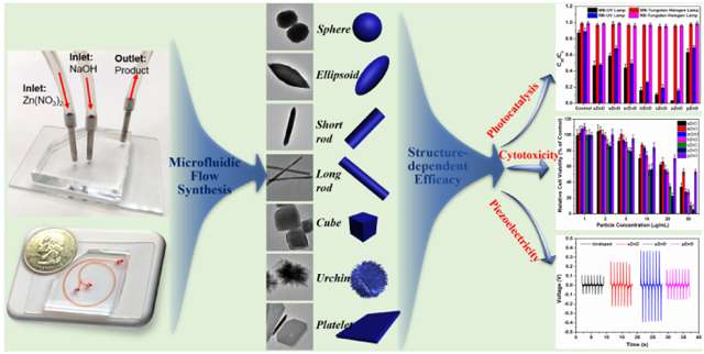
Microfluidics-based reactors enables the controllable synthesis of micro-/nanostructures for a broad spectrum of applications from materials science, bioengineering to medicine. In this study, we first develop a facile and straightforward flow synthesis strategy to control zinc oxide (ZnO) of different shapes (sphere, ellipsoid, short rod, long rod, cube, urchin, and platelet) on a few seconds time scale, based on the 1.5-run spiral-shaped microfluidic reactor with a relative short microchannel length of ca. 92 mm. The formation of ZnO is realized simply by mixing reactants through two inlet flows, one containing zinc nitrate and the other sodium hydroxide. The structures of ZnO are tuned by choosing appropriate flow rates and reactant concentrations of two inlet fluids. The formation mechanism behind microfluidics is proposed. The photocatalysis, cytotoxicity, and piezoelectric capabilities of as-synthesized ZnO from microreactors are further examined, and the structure-dependent efficacy is observed, where higher surface area ZnO structures generally behave better performance. These results bring new insights not only in the rational design of functional micro-/nanoparticles from microfluidics, but also for deeper understanding of the structure-efficacy relationship when translating micro-/nanomaterials into practical applications.
Keywords: Microfluidics, Zinc oxide, Photocatalysis, Cytotoxicity, Piezoelectric
Graphical abstract
1. Introduction
Zinc oxide (ZnO) has been extensively studied due to its excellent semiconducting and piezoelectric properties in potential applications of optoelectronics, sensors, catalysis, energy, environment, biomedical engineering, and so on.[1-4] To date, many methods have been developed to synthesize ZnO micro-/nanostructures, such as coprecipitation, hydrothermal, sol-gel, biosynthesis, supercritical fluid, spray pyrolysis, microwave, physical or chemical vapor deposition, and liquid-phase process.[5,6] However, it is noted that most of these methods always suffer from long time duration (at least several hours or days) for the nucleation, growth, and formation of well-defined ZnO micro-/nanoparticles. Despite this, precise control of the nucleation stage during the synthesis process is also a major challenge to these conventional batch methods, which make them more prone to low reproducibility. Therefore, developing a fast, simple, and effective method for the controllable synthesis of ZnO micro-/nanostructures is extremely necessary and highly desirable for basic research and industrial needs.
Relying on precise control over small volumes of fluids at micro-/nanoliter scale inside a centimeter-long or shorter microchannel, microfluidics-based microreactors explore new frontiers for rational design and controllable synthesis of functional micro-/nanostructures.[7-13] Compared to the conventional batch reactors, microreactors allow temporal and spatial control of materials synthesis in a more convenient and efficient manner. In addition, microfluidic systems offer many unique features that conventional batch reactors can hard to achieve, such as continuous and automatic operation in a closed environment, greatly reduced reaction volume and time, and enhanced mass and heat transfer. These advantages endow microreactors a promising platform for continuous and fast synthesis of ZnO micro-/nanoparticles.[14-16] However, to the best of our knowledge,[12,17-20] facile and controllable synthesis of well-defined micro-/nanoscale ZnO in microchannels that are simple in design yet favourable in performance is still not available. Also, there is a lack of a systematic investigation into the structure-efficacy relationship between ZnO particles and their applications such as photocatalysis, cytotoxicity, and piezoelectricity.
Herein, we report a facile, fast, and straightforward strategy to synthesize ZnO micro-/nanoparticles using a spiral-shaped microreactor and to systematically investigate the relationship between structure and efficacy. Miniaturized 1.5-run spiral-shaped microreactor with two inlet fluids, one containing zinc nitrate and the other sodium hydroxide, was employed to tune the particulate structures by changing the flow rates and the reactant concentrations. The underlying formation mechanism behind microfluidics was proposed. The structure-efficacy relationship of as-synthesized ZnO particles and their applications including photocatalysis, cytotoxicity, and piezoelectric activities were thoroughly examined.
2. Experimental details
2.1. Materials and reagents
Zinc nitrate (Zn(NO3)2), sodium hydroxide (NaOH), methylene blue (MB), Rhodamine B (RB), Cell-counting kit-8 (CCK-8), and dimethylformamide (DMF) were purchased from Sigma-Aldrich. Polydimethylsiloxane (PDMS Sylgard 184 kit) was purchased from Dow Corning. PVDF-TrFE powder was purchased from Piezotech ARKEMA Corp. Water used was from a Milli-Q water ultrapure water purification system. All chemicals were used as received without any further purification.
2.2. Fabrication of the 1.5-run spiral-shaped microfluidic reactor
The 1.5-run microfluidic spiral channel with two inlets and one outlet was fabricated using polydimethylsiloxane (PDMS) through soft lithography. Briefly, after designing the pattern with AutoCAD, a film mask was obtained (from Fine Line Imaging, Inc.) to fabricate the master mold using standard photolithography. A PDMS replica was then produced by pouring PDMS precursor (10:1 ratio for base and curing agent) onto the mold and curing the structures at 65 °C for at least 1 hour.
2.3. Synthesis of ZnO micro-/nanoparticles with different structures
The synthesis of ZnO was realized simply with one inlet containing Zn(NO3)2 and the other containing NaOH. The two inlet flows were pumped (Pump 33 DDS, Harvard Apparatus) into the spiral microchannel at different flow rates. The as-synthesized products were collected at the outlet and then directly put them into preheated oven at 80 °C for 1 hour. After washing several times with water, the obtained white solid was then dried and stored in a dry place for further analysis. The production yields of ZnO materials were calculated by the formulation: Yield (%)=(Wn/Wt) × 100, where Wn is the net weight of product, and Wt is the theoretical weight of the sample calculated based on 100% conversion of zinc nitrate to zinc oxide.
2.4. COMSOL simulation analysis
Reynolds number (Re) was calculated to determine if the fluids are in laminar flow regimes: Re = ⍴UL/μ, where the density (⍴~1000 kg/m3) and dynamic viscosity (μ ~0.001 Pa·s) of water are used for approximations, L is the characteristic length, and U is the average flow velocity, which could be obtained by: In our case with the spiral microchannel, W = 500 μm, H = 50 μm, when flow rate is 500 μL/min, U = 0.33 m/s, and Re = 7.6 < ~2300.
Therefore, the fluids are in laminar flow. We consider them as incompressible with no-slip boundary condition and neglect the gravity force for simplicity. The outlet is set to be fixed pressure with p = 0. The diffusion coefficient used is D = 5 × 10 − 10 m2/s.
2.5. Calculation of the time for the synthesis of ZnO via microfluidic device
To estimate the time for synthesis, firstly, the length of the channel is calculated, which is 92.12 mm. Then the volume of fluids in the channel is calculated to be 2.303 μL. Thus, with a flow rate of 500 μL/min, the time for the synthesis of ZnO structure is ~0.3 s (in the slowest case of 15 μL/min in this study, the time is ~9.2 s).
2.6. Photocatalysis tests of ZnO micro-/nanoparticles
The photocatalytic activity of ZnO micro-/nanoparticles was evaluated using the degradation of MB and RB under light irradiation in the dark at room temperature using UV lamp or Tungsten halogen lamp. RB and MB photocatalysis results were obtained in triplicates.
For the photocatalytic kinetic test of uZnO, MB (10−5 M) or RB (10−5 M) was mixed with uZnO (50 μg/mL), and then the suspension was irradiated under UV lamp (~30 W/m2 light intensity) or Tungsten halogen lamp (~80 W/m2 light intensity). At given time intervals (0, 2.5, 5, 10, 20, 30, and 60 min), the samples were taken out and centrifuged to remove photocatalyst particles for quantitative analysis using UV-VIS Spectrophotometer (SHIMADZU Corporation). The photodegradation rates (Ct/C0, where C0 and Ct are the concentrations of dyes before and after different irradiation times, respectively) were determined at a wavelength of 665 nm and 555 nm for MB and RB, respectively.
For the comparison of photocatalysis capability of different ZnO structures (sZnO, eZnO, srZnO, lrZnO, cZnO, uZnO, and pZnO), the irradiation time was chosen as 30 min, other procedures were similar as above.
For the reusability test of uZnO, MB (10−5 M) was mixed with uZnO (50 μg/mL), and then the suspension was irradiated under UV lamp for 30 min. The sample was centrifuged to obtain the supernatant for UV-Vis analysis, and the ZnO precipitation was redispersed into MB (10−5 M) for UV irradiation. The procedures were repeated for 10 times for examining the reusability of as-synthesized ZnO.
2.7. Cell culture and maintenance
PANC-1 cells (human pancreatic cancer cell line, ATCC) were cultured in high glucose DMEM (Dulbecco’s Modified Eagle’s Medium, ATCC) supplemented with 10% FBS (ATCC) and 1% penicillin-streptomycin (Sigma) in a humidified incubator at 37 °C with 5% CO2 and 95% air.
2.8. In vitro cytotoxicity evaluation of ZnO micro-/nanoparticles
The cytotoxicity of ZnO (sZnO, eZnO, srZnO, lrZnO, cZnO, uZnO, and pZnO) was evaluated using the CCK-8 viability assay. For the cytotoxicity evaluation, PANC-1 were seeded at a density of 5000 cells per well in 96-well plates. After incubating the cells with ZnO at a particle concentration ranging from 1 to 50 μg/mL for 24 h, 10 μL CCK-8 reagent was added to each well and incubated for 4 h. The absorbance of the resulting solution in each well was recorded at 450 nm with a microplate reader (TECAN SPARK 10M). Before reading, the plate was gently shaken on an orbital shaker for 30 s to ensure homogeneous distribution of color.
2.9. Piezoelectric tests of ZnO micro-/nanoparticles
The PVDF-TrFE composite (with cZnO, uZnO, or pZnO) solution was prepared through the following steps. Firstly, ZnO particles (30 wt%, relative to PVDF-TrFE) were added to DMF solution, and the mixture was sonicated for 30 min to ensure a homogeneous mixture. PVDF-TrFE powder (Piezotech® FC 30) was finally blended into the prepared solvent and the solution stayed in 60°C hot water bath for 6 hours with stirring.
We then used the following processes to fabricate the composite film. First, a piece of Dupont Kapton® film (50 mm × 75 mm × 25μm) was placed on a piece of glass substrate. Then the top surface of the film was sputtered a layer of 10 nm-thick gold serving as electrode. Next, a layer of pure 15% PVDF-TrFE solution (~30 μm thickness) was spin-coated on the gold electrode at 2000 rpm for 30 seconds. After the first PVDF-TrFE film was dried in an oven at ~50 °C, a thick layer of PVDF-TrFE composite solution (~30 μm) was applied on top of the pure PVDF-TrFE layer using spin-coating at 2000 rpm for 30 seconds. The film was then transferred into a water-based humidity chamber for at least 4 hours with a 90% relative humidity to create the mesoporous structure on the composite layer. To generate a high content of beta phase, the mesoporous film was treated by thermal annealing in an oven at 135°C for 2 hours. Electrical poling process was further employed where the mesoporous PVDF-TrFE composite film was sandwiched between two customized metal plates that were connected with a 50 mV/m electrical field for 1 hour, and the films treated at 100 °C during the poling process. Next, another layer of 10 nm gold was sputtered on top of the film.
The voltage output from these samples was obtained through the following test setup. A shaker (Model 2060E, The Modal Shop) was used to provide a linear motion with tunable force to the tested composite films. A metal rod with a circular force transducer (Model 208C02, PCB Piezoelectronics) screwed on its tip was inserted into the shaker. The tested composite film was covered by a piece of PDMS layer (5 mm × 5 mm × 2 mm) to protect it from being damaged by the striking head and was attached to a glass slide. The sample was then fixed to a vertical wall that was fastened on the table. At rest, the tip of the force transducer was about 2 mm away from the sample. During the test, the shaker was operating at 1 Hz and ~1 A, which exert a ~5 N force on the tested sample. The real-time force information was collected by the force transducer and recorded in Lab VIEW (National Instrument) on a desktop. The real-time voltage output was obtained directly by an oscilloscope (TDS 2014B, Tektronix) in a closed circuit.
2.10. Characterization
Transmission electron microscopy (TEM) was performed on a Tecnai F20ST field emission gun (FEG) transmission electron microscope operating at an accelerating voltage of 200 kV. Nitrogen adsorption–desorption measurements were carried out to determine the textural properties of ZnO materials by using a Quantachrome NOVA 4200e surface area analyzer at −196 °C. The surface area was calculated by the Brunauer–Emmett–Teller (BET) method. X-ray diffraction (XRD) analysis was conducted on the ZnO micro-/nanoparticles by using a Rigaku D/MAX 2000 diffractometer with Cu-Kα radiation. The operating voltage and current were 40 keV and 300 mA, respectively. A step size of 0.02° with a scanning angle (2θ) from 25° to 70° was used. The total scanning time was approximate 30 min.
3. Results and discussion
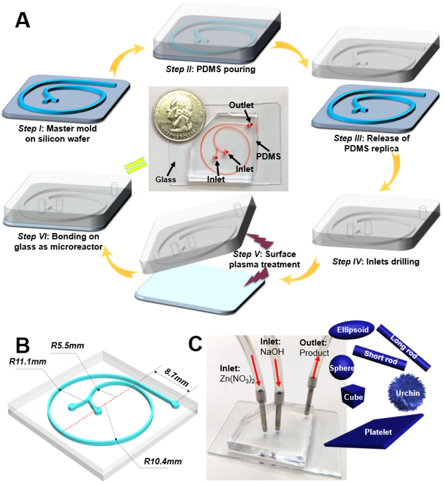
Microfluidic continuous flow synthesis of ZnO with different structures was realized in the 1.5-run spiral-shaped microfluidic reactor with two inlets and one outlet (Figure 1A). The microchannel is composed of three arcs with the diameters of 11.0, 20.8, and 22.2 mm (the lengths of each arc are 15.88, 32.67, and 34.87 mm, respectively) and a short straight part of 8.70 mm from the arc to the outlet (Figure 1B). The width and height of the spiral channel are 500 and 50 μm, respectively. Given the unique features of microfluidics (especially the low Reynolds number), such a 1.5-run microreactor is expected to achieve rapid and intensive mixing inside the microchannel, and thus to produce ZnO of different structures in a fast and continuous way. To demonstrate this, two inlet flows, one containing zinc nitrate (Zn(NO3)2) and the other sodium hydroxide (NaOH), were pumped (Pump 33 DDS, Harvard Apparatus) into the microchannel at room temperature (Figure 1C). The white colloidal suspension was collected from the outlet, followed by post-thermal treatment, and the structures of as-synthesized products were examined by transmission electron microscopy (TEM).
Figure 1.
Microfluidic reactor development for controllable synthesis of ZnO particles. (A) Fabrication procedure of 1.5-loop spiral-shaped microfluidic device. The central image is a photograph of the fabricated microreactor with a U.S. quarter coin for scale. The microfluidic channel was filled with a red dye for visualization. (B) is a scheme showing the design parameters of microreactor. (C) is the photograph showing operation of the microfluidic system with two inlets and one outlet for ZnO synthesis. Objects are not drawn to scale.
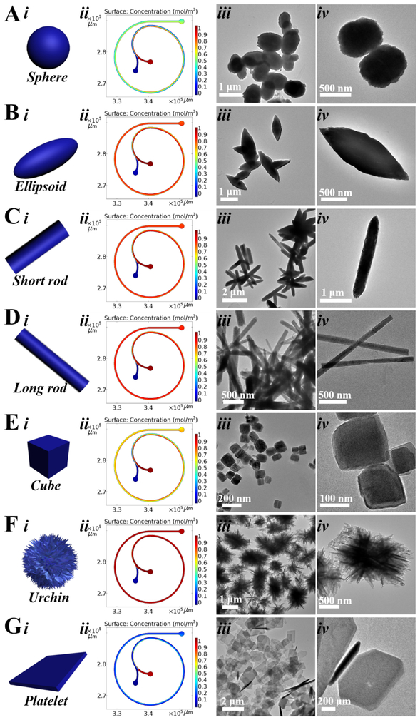
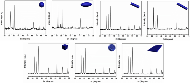
Different from other microchannel geometries, [12,14-20] the spiral shape presents unique transverse Dean flow,[21-26] which permits fast and efficient production of ZnO micro-/nanostructures. As shown in Figure 2 and Table 1, the COMSOL simulation analysis revealed that, at different flow rates combinations, the two reactant fluids can be rapidly and intensively mixed (Figure 2-column ii), and the structure control of ZnO can be realized by seconds time scale. In agreement with the simulation results, TEM results confirmed that well-defined nearly sphere (sZnO, Figure 2A), ellipsoid (eZnO, Figure 2B), short rod (srZnO, Figure 2C), long rod (lrZnO, Figure 2D), cubic (cZnO, Figure 2E), urchin-like (uZnO, Figure 2F), and platelet-like ZnO (pZnO, Figure 2G) particles can be successfully obtained by simply changing the flow rates and reactant concentrations of two inlet fluids. Specifically, when the flow rate of zinc nitrate was 25 μL/min or below, high aspect ratio ZnO structures (such as srZnO, lrZnO, and uZnO) could be obtained. Increasing the concentrations of reactants could yield ZnO products with larger surface area (especially for cZnO and uZnO, Table 1). In addition, the larger the difference of the flow rates of two inlet fluids, the more anisotropic structure appears (such as eZnO, srZnO, lrZnO, uZnO, and pZnO). The production amounts of these ZnO structures can generally achieve from few tens of milligrams to several grams per day, and the yields of all seven materials are in a range of about 95%-98%, which is typically high because of the intensive and efficient mixing performance inside microchannel. Nitrogen sorption analysis showed that uZnO has the highest Brunauer–Emmett–Teller (BET) surface area, followed by cZnO, and then lrZnO, and finally sZnO, eZnO, srZnO, and pZnO (Table 1). The compositions of all these ZnO micro-/nanoparticles were further analyzed by X-ray diffraction (XRD) and compared to the standard Powder Diffraction File (PDF) Database. The results showed that all samples exhibit various Bragg's reflection peaks at (100), (002), (101), (102), (110), (103), (200), (112), and (201), indicating the presence of crystalline ZnO structures (Figure 3).[27-29]
Figure 2.
COMSOL simulation results and transmission electron microscopy (TEM) images of sZnO (A), eZnO (B), srZnO (C), lrZnO (D), cZnO (E), uZnO (F), and pZnO (G).
Table 1.
Operation parameters and properties of as-synthesized ZnO micro-/nanoparticles with different structures.
| Sample name |
Inlet (Zn(NO3)2) | Inlet (NaOH) | Particle Shape |
Dimension* (mn) | Surface area** (m2/g) |
||
|---|---|---|---|---|---|---|---|
| Concentration | Flow Rate | Concentration | Flow Rate | ||||
| sZnO | 30 mM | 50 μL/min | 12.5 mM | 50 μL/min | Sphere | 583±124 | 13.15 |
| eZnO | 30 mM | 50 μL/min | 12.5 mM | 200 μL/min | Ellipsoid | (476±108)×(1340±257) | 10.22 |
| srZnO | 30 mM | 20 μL/min | 12.5 mM | 100 μL/min | Short rod | (285±44)×(1667±301) | 16.54 |
| lrZnO | 30 mM | 2.5 μL/min | 12.5 mM | 15 μL/min | Long rod | (169±23)×(2212±379) | 25.53 |
| cZnO | 300 mM | 50 μL/min | 125 mM | 100 ×L/min | Cube | 153±36 | 45.40 |
| uZnO | 300 mM | 25 μL/min | 125 mM | 500 μL/min | Urchin | 1106±218 | 64.67 |
| pZnO | 300 mM | 100 μL/min | 125 mM | 25 μL/min | Platelet | (159±30)×(2008±412) | 8.23 |
All values indicate the main properties of particles such as diameter, width, length, and height.
All values were determined by the BET method of nitrogen sorption analysis.
Figure 3.
XRD patterns of as-synthesized ZnO micro-/nanoparticles.
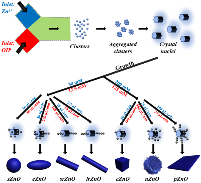
Based on above observations, although the microscopic details of the nucleus and growth of ZnO have still not been effectively and precisely elucidated to date,[30] we tried to provide a plausible explanation to help for understanding the microreaction process and structural control achieved in the microreactor. Generally, the formation of ZnO consists of three stages: 1) reaction between Zn2+ and OH− species in the precursor solution; 2) homogeneous nucleation through aggregation of amorphous clusters; 3) oriented attachment of the formed nuclei in the preferred direction depending on the reaction conditions (Figure 4).[30,31] General reaction equations that are commonly reported for elucidating the formation of ZnO are shown below:
| (1) |
| (2) |
| (3) |
Figure 4.
Schematic illustration for the formation of the as-synthesized ZnO micro-/nanoparticles with different structures (Objects are not drawn to scale).
The reaction process of solid precipitation typically starts from the formation of Zn(OH)2 followed by the conversion into ZnO (Figure 4).[14,30] Depending upon the flow rates that determine the reactant concentrations at the interface of two fluids, the crystal nuclei will evolve into different structures under the given reaction conditions (Table 1). Specifically, the spiral-shaped microchannel allows for ultrafast mixing, which results in rapid nucleation (Figure 4). At lower concentrations of Zn(NO3)2 (30 mM) and NaOH (12.5 mM), when their flow rates are both set as 50 μL/min, the microcrystals would attach themselves on the nuclei surface for lowering the surface energy, and thus forming spherical sZnO.[32,33] When increasing the flow rate of NaOH fluid to 200 μL/min while keeping the other constant, the increasing concentration of OH− would accelerate crystal growth along the c-axis to form ellipsoidal eZnO.[34,35] Further increasing the molar ratios of OH− to Zn2+ could lead to form rod-shaped ZnO (srZnO and lrZnO) elongated along the c-axis direction due to the preferably adsorption of [Zn(OH)4]2− on the positively charged (0001) polar face of ZnO nuclei.[30,31,33] However, at higher molar concentrations (300 mM Zn2+ and 125 mM OH−), the growth along the c-axis would be probably depressed. [36] When the flow rates of Zn2+ and OH− fluids are set as 50 and 100 μL/min, respectively, ZnO nuclei would grow in random orientations to form polyhedral cubic cZnO (and fewer hexagonal prisms).[37,38] If the flow rates of Zn2+ and OH− fluids are set as 25 and 500 μL/min, respectively, the significantly increased concentration of OH− would decrease the concentration of [Zn(OH)4]2− due to the initial fast nucleation of ZnO. The existence of relatively large concentration of OH− would further result in more active sites generated on the surface of ZnO nuclei and grow into uZnO.[39] When the flow rates of Zn2+ and OH− fluids are 100 and 25 μL/min, respectively, the excessive Zn2+ would adsorb on the negative polar (000) plane for directing the growth of ZnO nuclei, resulting in the plate form.[33,40] Therefore, microfluidics provides a facile, straightforward, and efficient way for tuning the structures of ZnO by easily changing the flow rates and the interface concentrations of reactants (Figure 4).
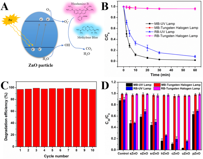
Considering the ease and feasible of microfluidics-enabled structural control, the as-synthesized ZnO micro-/nanomaterials provide great convenience for systematically probing the effect of particulate structures on the application efficacy. We first examined the structure-efficacy relationship of ZnO particles on photocatalysis. In the field of photocatalysis today, ZnO has attracted great attentions and emerged as a promising candidate to solve the environmental problems (such as dyes pollutants of wastewater stream) due to its extraordinary characteristics including strong oxidation ability, wide band gap, and large free-exciton binding energy (Figure 5A).[41] To evaluate the photocatalytic activity of as-synthesized ZnO, methylene blue (MB, 10−5 M) and Rhodamine B (RB, 10−5 M) were chosen for the photodegradation tests at a particle concentration of 50 μg/mL under UV lamp light source (~30 W/m2 light intensity) or Tungsten halogen lamp light source (~80 W/m2 light intensity). UV-vis absorption spectra were recorded to quantitatively calculate the degradation efficiency of MB (665 nm) and RB (555 nm). Figure 5B shows the photodegradation kinetics of MB and RB treated with uZnO under different light sources. The results suggested that UV lamp irradiation significantly enhanced degradation efficiency for both MB (~98.1%) and RB (~91.5%) within 60 min compared to Tungsten halogen lamp irradiation (less than 4%). In addition, under UV light irradiation, photodegradation of MB appeared to be faster than that of RB, and the degradation of MB almost completely finished within 30 min. The photodegradation of MB by uZnO exhibited no obvious difference within 10 cycles (Figure 5C), indicating robust stability of ZnO photocatalyst from microfluidic reactors. The structural effect of ZnO on the degradation efficiency of MB and RB was further examined with a 30 min light irradiation. As shown in figure 5D, under Tungsten halogen light treatment, all seven ZnO samples have neglectable and similar photodegradation activity as control system without the addition of ZnO. Whereas, under UV irradiation, the photodegradation activity of ZnO exhibited an obvious structure-dependent manner in the order of uZnO>cZnO>lrZnO>srZnO ≈ sZnO>eZnO ≈pZnO. These results not only confirm the feasibility of microfluidics in the synthesis of robust ZnO photocatalyst, but also shed new light on the rational design of ZnO for organic pollutants removal in practical environment settings.
Figure 5.
Structure-efficacy relationship of sphere (sZnO), ellipsoid (eZnO), short rod (srZnO), long rod (lrZnO), cubic (cZnO), urchin-like (uZnO), and platelet-like ZnO (pZnO) materials toward photocatalysis. (A) General mechanism of the photocatalysis on ZnO particle. (B) Photocatalysis degradation kinetics of MB and RB using uZnO under UV lamp (30 W/m2) and Tungsten halogen lamp (80 W/m2) treatment. C0 is the initial concentration of MB and RB dye solution, while C represents the remaining dye concentration of MB and RB after that time interval. (C) The reusability test of uZnO in the photodegradation of MB. (D) The structure effect of ZnO on the photocatalysis of MB and RB under UV lamp (30 W/m2) and Tungsten halogen lamp treatment (80 W/m2).
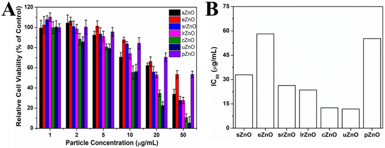
We next examined the structure-efficacy relationship of ZnO particles on cytotoxicity activity due to the promising potential of ZnO in cancer therapy.[42,43] When nanoparticles are localized into the acidic tumor microenvironment,[44] the cytotoxicity of ZnO materials may be generated through increased intracellular Zn2+ level by dissolution, increased reactive oxidative stress, decreased mitochondrial membrane potential, or genotoxicity.[45] All these features, to some extent, are regulated by the structures of ZnO.[46,47] To demonstrate this, PANC-1 (human pancreatic cancer cell line) cells were incubated with various concentrations of as-synthesized ZnO micro-/nanoparticles from 1 to 50 μg/mL, and then the cytotoxicity was assessed by CCK-8 assay. As shown in figure 6A, the results showed that the toxicity of ZnO exhibited an obvious particle concentration-dependent manner. The higher the particle concentration, the higher the cytotoxicity of ZnO. In addition to particle concentration, particle structure-dependent cytotoxicity was also observed as expected. According to the calculated half inhibitory concentration (IC50) results of ZnO against PANC-1 cells (Figure 6B), cZnO and uZnO have the lowest IC50 values (~12 μg/mL), indicating their strongest anticancer potential. Whereas, eZnO and pZnO have the highest IC50 values (nearly 5 times higher than cZnO and uZnO), which means their relative weakest anticancer cell proliferation activities. Combining with the results from Table 1, there is a clear positive correlation relationship between particle surface area and cytotoxicity. One of the possible reasons can be attributed to higher dissolution rates of Zn2+ from larger surface area of ZnO nanostructures. These findings reveal that the structure of ZnO plays significant roles in its biological performance, and thus highlight the importance of structural design when engineering ZnO-based nanomedicines.
Figure 6.
Structure-efficacy relationship of sphere (sZnO), ellipsoid (eZnO), short rod (srZnO), long rod (lrZnO), cubic (cZnO), urchin-like (uZnO), and platelet-like ZnO (pZnO) toward cytotoxicity. (A) PANC-1 cell viability after treated with ZnO of different structures at particle concentrations ranging from 1 to 50 μg/mL for 24 h. (B) The corresponding IC50 values of ZnO of different structures from (A).
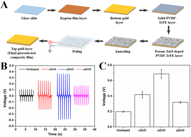
After unveiling the structure-efficacy relationship of ZnO particles on photocatalysis and cytotoxicity activities, we further examined the structure effect of ZnO on piezoelectric activity. Forming a piezoelectric composite material that is composed of the piezo-ceramic particles (such as ZnO; BaTiO3; Lead zirconate titanate, PZT; AlN) and the soft piezo polymers (such as polyvinylidene fluoride, PVDF; polyvinylidene fluoride trifluoroethylene, PVDF-TrFE) is the key to improve the electro-mechanical efficiency of energy harvesting devices and structures.[48] Among of piezo-ceramic materials, ZnO is a promising candidate to make such a composite due to its relative low cost, easy precursors, and controllable structures. By rational design of ZnO structure, its surface area can be optimized, which may lead to enhanced voltage output acquired from the piezoelectric composites due to the increased electromechanical response.[49] To demonstrate this, we chose three kinds of as-synthesized ZnO (cZnO, uZnO, and pZnO) with distinct surface areas (Table 1) and then mixed them respectively with the piezopolymer PVDF-TrFE for piezoelectric performance test (Figure 7A). As shown in figure 7B, compared to the undoped PVDF-TrFE, the ZnO-doped ones exhibit obviously enhanced voltage response. In addition, the structure-dependent voltage output was observed, uZnO having the largest surface area generated the highest voltage output, which is nearly 3.5 times higher than the undoped PVDF-TrFE. Whereas, pZnO with the relative smallest surface area provided the lowest voltage improvement, but still 1.6 times higher than the undoped material (Figure 7C). These results may raise a new strategy to make piezoelectricity-enhanced composites that can greatly serve for energy harvesting applications.
Figure 7.
Structure-efficacy relationship of as-synthesized ZnO toward piezoelectricity. (A) Schematic experimental workflow for the preparation of piezoelectric composite materials (ZnO-doped PVDF-TrFE). (B) Four spectra voltage responses acquired from undoped, cZnO-doped, uZnO-doped, and pZnO-doped PVDF-TrFE thin film samples. (C) The peak-to-peak voltage outputs from (B).
4. Conclusions
In summary, we developed a facile, fast, and effective microfluidic flow synthesis strategy for rational design of ZnO micro-/nanostructures and unveiled its structure-efficacy relationship toward enhanced photocatalysis, cytotoxicity, and piezoelectric activities. A miniaturized 1.5-run spiral-shaped microfluidic reactor was specially designed to synthesize ZnO particles on a few seconds time scale inside a microchannel. Using one inlet flow containing Zn(NO3)2 and the other NaOH, seven distinct ZnO structures (sphere, ellipsoid, short rod, long rod, cube, urchin, and platelet) were formed by tuning the flow rates and reactant concentrations of two inlet fluids. The formation mechanism of controllable ZnO structures was proposed for understanding the processes behind microfluidics. Structural effect of the as-synthesized ZnO on photocatalysis, cytotoxicity, and piezoelectricity was confirmed, where ZnO structures having larger surface area generally demonstrate better efficacy. These results not only provide new insights for engineering controllable micro-/nanostructures through microfluidic reactors, but also pave the foundation towards versatile structural designs with unique physical and biochemical properties applied to practical applications.
Highlights.
Spiral shaped laminar flow microreactor for ZnO micro-/nanomaterials synthesis
Seven distinct ZnO were formed by tuning the flow rates or reactant concentrations
Microfluidics-enabled controllable formation mechanism was proposed
Structure-dependent photocatalysis, cytotoxicity, and piezoelectric activities
ZnO structures having larger surface area generally demonstrate enhanced efficacy
ACKNOWLEDGMENT
This work was sponsored by the NIH Director’s Transformative Research Award (R01HL137157), and NSF grants (ECCS 1128677, 1309686, 1509369). We gratefully acknowledge the support from the Electron Microscope Facility at Dartmouth College.
Footnotes
Publisher's Disclaimer: This is a PDF file of an unedited manuscript that has been accepted for publication. As a service to our customers we are providing this early version of the manuscript. The manuscript will undergo copyediting, typesetting, and review of the resulting proof before it is published in its final citable form. Please note that during the production process errors may be discovered which could affect the content, and all legal disclaimers that apply to the journal pertain.
REFERENCES
- [1].Swain B, Hong MH, Kang L, Kim BS, Kim NH, Lee CG, Optimization of CdSe nanocrystals synthesis with a microfluidic reactor and development of combinatorial synthesis process for industrial production, Chem. Eng. J 308 (2017) 311–321. doi: 10.1016/j.cej.2016.09.020. [DOI] [Google Scholar]
- [2].Vittal R, Ho KC, Zinc oxide based dye-sensitized solar cells: A review, Renew. Sust. Energ. Rev 70 (2017) 920–935. doi: 10.1016/j.rser.2016.11.273. [DOI] [Google Scholar]
- [3].Mishra PK, Mishra H, Ekielski A, Talegaonkar S, Vaidya B, Zinc oxide nanoparticles: a promising nanomaterial for biomedical applications, Drug Discov. Today 22 (2017) 1825–1834. doi: 10.1016/j.drudis.2017.08.006. [DOI] [PubMed] [Google Scholar]
- [4].Rahman F, Zinc oxide light-emitting diodes: a review, Opt. Eng 58 (2019) 010901. doi: 10.1117/1.OE.58.1.010901. [DOI] [Google Scholar]
- [5].Moezzi A, McDonagh AM, Cortie MB, Zinc oxide particles: Synthesis, properties and applications, Chem. Eng. J 185–186 (2012) 1–22. doi: 10.1016/j.cej.2012.01.076. [DOI] [Google Scholar]
- [6].Wang ZL, Zinc oxide nanostructures: growth, properties and applications, J. Phys. Condens. Matter 16 (2004) R829–R858. doi: 10.1088/0953-8984/16/25/R01. [DOI] [Google Scholar]
- [7].Marre S, Jensen KF, Synthesis of micro and nanostructures in microfluidic systems., Chem. Soc. Rev 39 (2010) 1183–1202. doi: 10.1039/b821324k. [DOI] [PubMed] [Google Scholar]
- [8].Song Y, Hormes J, Kumar CSSR, Microfluidic Synthesis of Nanomaterials, Small. 4 (2008) 698–711. doi: 10.1002/smll.200701029. [DOI] [PubMed] [Google Scholar]
- [9].Hao N, Nie Y, Zhang JXJ, Microfluidics for silica biomaterials synthesis: opportunities and challenges, Biomater. Sci 7 (2019) 2218–2240. doi: 10.1039/C9BM00238C. [DOI] [PMC free article] [PubMed] [Google Scholar]
- [10].Zhao C-X, He L, Qiao SZ, Middelberg APJ, Nanoparticle synthesis in microreactors, Chem. Eng. Sci 66 (2011) 1463–1479. doi: 10.1016/j.ces.2010.08.039. [DOI] [Google Scholar]
- [11].Elvira KS, Casadevall i Solvas X, Wootton RCR, de Mello AJ, The past, present and potential for microfluidic reactor technology in chemical synthesis., Nat. Chem 5 (2013) 905–915. doi: 10.1038/nchem.1753. [DOI] [PubMed] [Google Scholar]
- [12].Hao N, Nie Y, Zhang JXJ, Microfluidic synthesis of functional inorganic micro/nanoparticles and applications in biomedical engineering, Int. Mater. Rev 63 (2018) 461–487. doi: 10.1080/09506608.2018.1434452. [DOI] [Google Scholar]
- [13].Valencia PM, Farokhzad OC, Karnik R, Langer R, Microfluidic technologies for accelerating the clinical translation of nanoparticles, Nat. Nanotechnol 7 (2012) 623–629. doi: 10.1038/nnano.2012.168. [DOI] [PMC free article] [PubMed] [Google Scholar]
- [14].Roig Y, Marre S, Cardinal T, Aymonier C, Synthesis of exciton luminescent ZnO nanocrystals using continuous supercritical microfluidics, Angew. Chem. Int. Ed 50 (2011) 12071–12074. doi: 10.1002/anie.201106201. [DOI] [PubMed] [Google Scholar]
- [15].Kang HW, Leem J, Yoon SY, Sung HJ, Continuous synthesis of zinc oxide nanoparticles in a microfluidic system for photovoltaic application, Nanoscale. 6 (2014) 2840–2846. doi: 10.1039/c3nr06141h. [DOI] [PubMed] [Google Scholar]
- [16].Baruah A, Jindal A, Acharya C, Prakash B, Basu S, Ganguli AK, Microfluidic reactors for the morphology controlled synthesis and photocatalytic study of ZnO nanostructures, J. Micromech. Microeng 27 (2017) 035013. doi: 10.1088/1361-6439/aa5bc4. [DOI] [Google Scholar]
- [17].Jung JY, Park N-K, Han S-Y, Han GB, Lee TJ, Ryu SO, Chang C-H, The growth of the flower-like ZnO structure using a continuous flow microreactor, Curr. Appl. Phys 8 (2008) 720–724. doi: 10.1016/j.cap.2007.04.026. [DOI] [Google Scholar]
- [18].Choi C-H, Chang C, Aqueous Synthesis of Tailored ZnO Nanocrystals, Nanocrystal Assemblies, and Nanostructured Films by Physical Means Enabled by a Continuous Flow Microreactor, Cryst. Growth Des 14 (2014) 4759–4767. doi: 10.1021/cg500911w. [DOI] [Google Scholar]
- [19].Li S, Gross GA, Günther PM, Köhler JM, Hydrothermal micro continuous-flow synthesis of spherical, cylinder-, star- and flower-like ZnO microparticles, Chem. Eng. J 167 (2011) 681–687. doi: 10.1016/j.cej.2010.09.083. [DOI] [Google Scholar]
- [20].Choi C-H, Su Y-W, Chang C, Effects of fluid flow on the growth and assembly of ZnO nanocrystals in a continuous flow microreactor, CrystEngComm. 15 (2013) 3326–3333. doi: 10.1039/c3ce26699k. [DOI] [Google Scholar]
- [21].Di Carlo D, Inertial microfluidics., Lab Chip. 9 (2009) 3038–3046. doi: 10.1039/b912547g. [DOI] [PubMed] [Google Scholar]
- [22].Hao N, Nie Y, Xu Z, Zhang JXJ, Ultrafast microfluidic synthesis of hierarchical triangular silver core-silica shell nanoplatelet toward enhanced cellular internalization, J. Colloid Interf. Sci 542 (2019) 370–378. doi: 10.1016/j.jcis.2019.02.021. [DOI] [PMC free article] [PubMed] [Google Scholar]
- [23].Hao N, Nie Y, Xu Z, Closson AB, Usherwood T, Zhang JXJ, Microfluidic continuous flow synthesis of functional hollow spherical silica with hierarchical spongelike large porous shell, Chem. Eng. J 366 (2019) 433–438. doi: 10.1016/j.cej.2019.02.095. [DOI] [PMC free article] [PubMed] [Google Scholar]
- [24].Hao N, Nie Y, Closson AB, Zhang JXJ, Microfluidic synthesis and on-chip enrichment application of two-dimensional hollow sandwich-like mesoporous silica nanosheet with water ripple-like surface, J. Colloid Interf. Sci 539 (2019) 87–94. doi: 10.1016/j.jcis.2018.12.040. [DOI] [PMC free article] [PubMed] [Google Scholar]
- [25].Hao N, Nie Y, Shen T, Zhang JXJ, Microfluidics-enabled rational design of immunomagnetic nanomaterials and their shape effect on liquid biopsy, Lab Chip. 18 (2018) 1997–2002. doi: 10.1039/C8LC00273H. [DOI] [PMC free article] [PubMed] [Google Scholar]
- [26].Hao N, Nie Y, Zhang JXJ, Microfluidic Flow Synthesis of Functional Mesoporous Silica Nanofibers with Tunable Aspect Ratios, ACS Sustain. Chem. Eng 6 (2018) 1522–1526. doi: 10.1021/acssuschemeng.7b03527. [DOI] [Google Scholar]
- [27].Demoisson F, Piolet R, Bernard F, Hydrothermal Synthesis of ZnO Crystals from Zn(OH) 2 Metastable Phases at Room to Supercritical Conditions, Cryst. Growth Des 14 (2014) 5388–5396. doi: 10.1021/cg500407r. [DOI] [Google Scholar]
- [28].Wang M, Zhou Y, Zhang Y, Hahn SH, Kim EJ, From Zn(OH)2 to ZnO: a study on the mechanism of phase transformation, CrystEngComm. 13 (2011) 6024. doi: 10.1039/c1ce05502j. [DOI] [Google Scholar]
- [29].Jitianu M, Goia DV, Zinc oxide colloids with controlled size, shape, and structure, J. Colloid Interf. Sci 309 (2007) 78–85. doi: 10.1016/j.jcis.2006.12.020. [DOI] [PubMed] [Google Scholar]
- [30].Mohammadi E, Aliofkhazraei M, Hasanpoor M, Chipara M, Hierarchical and Complex ZnO Nanostructures by Microwave-Assisted Synthesis: Morphologies, Growth Mechanism and Classification, Crit. Rev. Solid State Mater. Sci 43 (2018) 475–541. doi: 10.1080/10408436.2017.1397501. [DOI] [Google Scholar]
- [31].Barhoum A, Melcher J, Van Assche G, Rahier H, Bechelany M, Fleisch M, Bahnemann D, Synthesis, growth mechanism, and photocatalytic activity of Zinc oxide nanostructures: porous microparticles versus nonporous nanoparticles, J. Mater. Sci 52 (2017) 2746–2762. doi: 10.1007/s10853-016-0567-3. [DOI] [Google Scholar]
- [32].Wahab R, Mishra A, Yun S Il, Hwang IH, Mussarat J, Al-Khedhairy AA, Kim YS, Shin HS, Fabrication, growth mechanism and antibacterial activity of ZnO micro-spheres prepared via solution process, Biomass Bioenerg. 39 (2012) 227–236. doi: 10.1016/j.biombioe.2012.01.005. [DOI] [Google Scholar]
- [33].Zhao X, Li M, Lou X, Sol-gel assisted hydrothermal synthesis of ZnO microstructures: Morphology control and photocatalytic activity, Adv. Powder Technol 25 (2014) 372–378. doi: 10.1016/j.apt.2013.06.004. [DOI] [Google Scholar]
- [34].Chittofrati A, Matijević E, Uniform particles of zinc oxide of different morphologies, Colloids Surf. 48 (1990) 65–78. doi: 10.1016/0166-6622(90)80219-T. [DOI] [Google Scholar]
- [35].Oliveira APA, Hochepied J-F, Grillon F, Berger M-H, Controlled Precipitation of Zinc Oxide Particles at Room Temperature, Chem. Mater 15 (2003) 3202–3207. doi: 10.1021/cm0213725. [DOI] [Google Scholar]
- [36].Baruah S, Dutta J, Hydrothermal growth of ZnO nanostructures, Sci. Technol. Adv. Mater 10 (2009) 013001. doi: 10.1088/1468-6996/10/1/013001. [DOI] [PMC free article] [PubMed] [Google Scholar]
- [37].Wrobel G, Piech M, Dardona S, Ding Y, Gao P-X, Seedless Synthesis and Thermal Decomposition of Single Crystalline Zinc Hydroxystannate Cubes, Cryst. Growth Des 9 (2009) 4456–4460. doi: 10.1021/cg900486r. [DOI] [Google Scholar]
- [38].Ludi B, Niederberger M, Zinc oxide nanoparticles: chemical mechanisms and classical and non-classical crystallization, Dalt. Trans 42 (2013) 12554. doi: 10.1039/c3dt50610j. [DOI] [PubMed] [Google Scholar]
- [39].Zhang H, Yang D, Ji Y, Ma X, Xu J, Que D, Low Temperature Synthesis of Flowerlike ZnO Nanostructures by Cetyltrimethylammonium Bromide-Assisted Hydrothermal Process, J. Phys. Chem. B 108 (2004) 3955–3958. doi: 10.1021/jp036826f. [DOI] [Google Scholar]
- [40].Zhang J, Liu H, Wang Z, Ming N, Low-temperature growth of ZnO with controllable Shapes and band gaps, J. Cryst. Growth 310 (2008) 2848–2853. doi: 10.1016/j.jcrysgro.2008.02.014. [DOI] [Google Scholar]
- [41].Lee KM, Lai CW, Ngai KS, Juan JC, Recent developments of zinc oxide based photocatalyst in water treatment technology: A review, Water Res. 88 (2016) 428–448. doi: 10.1016/j.watres.2015.09.045. [DOI] [PubMed] [Google Scholar]
- [42].Zhang H, Chen B, Jiang H, Wang C, Wang H, Wang X, A strategy for ZnO nanorod Mediated multi-mode cancer treatment, Biomaterials. 32 (2011) 1906–1914. doi: 10.1016/j.biomaterials.2010.11.027. [DOI] [PubMed] [Google Scholar]
- [43].Cai X, Luo Y, Yan H, Du D, Lin Y, PH-Responsive ZnO Nanocluster for Lung Cancer Chemotherapy, ACS Appl. Mater. Interfaces 9 (2017) 5739–5747. doi: 10.1021/acsami.6b13776. [DOI] [PubMed] [Google Scholar]
- [44].Warburg O, On the Origin of Cancer Cells, Science. 123 (1956) 309–314. doi: 10.1126/science.123.3191.309. [DOI] [PubMed] [Google Scholar]
- [45].Pandurangan M, Kim DH, In vitro toxicity of zinc oxide nanoparticles: a review, J. Nanopart. Res 17 (2015) 158. doi: 10.1007/s11051-015-2958-9. [DOI] [Google Scholar]
- [46].Ancona A, Canavese G, Racca L, Chiodoni A, Canta M, Dumontel B, Engelke H, Limongi T, Cauda V, Enhanced biostability and cellular uptake of zinc oxide nanocrystals shielded with a phospholipid bilayer, J. Mater. Chem. B 5 (2017) 8799–8813. doi: 10.1039/c7tb02229h. [DOI] [PMC free article] [PubMed] [Google Scholar]
- [47].Hsiao I, Huang Y, Titanium Oxide Shell Coatings Decrease the Cytotoxicity of ZnO Nanoparticles, Chem. Res. Toxicol 24 (2011) 303–313. doi: 10.1021/tx1001892. [DOI] [PubMed] [Google Scholar]
- [48].Xu Z, Liu Y, Dong L, Closson AB, Hao N, Oglesby M, Escobar GP, Fu S, Han X, Wen C, Liu J, Feldman MD, Chen Z, Zhang JXJ, Tunable Buckled Beams with Mesoporous PVDF-TrFE/SWCNT Composite Film for Energy Harvesting, ACS Appl. Mater. Interfaces 10 (2018) 33516–33522. doi: 10.1021/acsami.8b09310. [DOI] [PMC free article] [PubMed] [Google Scholar]
- [49].Sinha N, Goel S, Joseph AJ, Yadav H, Batra K, Gupta MK, Kumar B, Y-doped ZnO nanosheets: Gigantic piezoelectric response for an ultra-sensitive flexible piezoelectric nanogenerator, Ceram. Int 44 (2018) 8582–8590. doi: 10.1016/j.ceramint.2018.02.066. [DOI] [Google Scholar]


