Abstract
Sputtered iridium oxide films (SIROFs) deposited by DC reactive sputtering from an iridium metal target have been characterized in vitro for their potential as neural recording and stimulation electrodes. SIROFs were deposited over gold metallization on flexible multielectrode arrays fabricated on thin (15 μm) polyimide substrates. SIROF thickness and electrode areas of 200–1300 nm and 1960–125,600 μm2, respectively, were investigated. The charge-injection capacities of the SIROFs were evaluated in an inorganic interstitial fluid model in response to charge-balanced, cathodal-first current pulses. Charge injection capacities were measured as a function of cathodal pulse width (0.2–1 ms) and potential bias in the interpulse period (0.0 to 0.7 V vs. Ag|AgCl). Depending on the pulse parameters and electrode area, charge-injection capacities ranged from 1–9 mC/cm2, comparable with activated iridium oxide films (AIROFs) pulsed under similar conditions. Other parameters relevant to the use of SIROF on nerve electrodes, including the thickness dependence of impedance (0.05–105 Hz) and the current necessary to maintain a bias in the interpulse region were also determined.
Keywords: neural stimulation, neural recording, microelectrode, iridium oxide, sputtering
INTRODUCTION
Emerging prostheses and therapies involving neural stimulation electrodes implanted in the central or peripheral nervous system will require charge-injection levels that challenge the capabilities of noble metals.1,2 Reported electrical thresholds for eliciting a neuronal response in brain structures with indwelling cortical microelectrodes are about 1 nC per phase, with functional thresholds still uncertain.3,4 Typically, intracortical electrodes have an active geometric area of about 1000 μm2 resulting in a minimum charge density of 0.1 mC/cm2. For deep brain stimulation with microelectrodes, charge densities on the order of 0.4 mC/cm2 are expected.5 Stimulation studies with retinal surface electrodes have identified perceptual thresholds in humans that vary from 24 nC to >1 μC per phase.6–8 Even at the lower threshold values, charge densities over 1 mC/cm2 may be necessary to obtain high resolution in visual prostheses that stimulate the retina.9 For charge-injection densities over approximately 0.2 mC/cm2, based on geometric surface area, low impedance coatings of activated iridium oxide films (AIROFs) or high-porosity (fractal) titanium nitride (f-TiN) are usually employed.10,11 Iridium oxide films inject charge via reversible reduction and oxidation between Ir3+/Ir4+ valence states within the oxide film, while f-TiN is a capacitive electrode that operates by charging and discharging the double-layer at the TiN-electrolyte interface. Other materials that are potentially capable of high levels of charge injection, such as carbon nanotubes and conductive polymers, are also being investigated but there is presently little in vivo experience with these materials as stimulation electrodes.12,13 More recent efforts to employ moderately porous films of platinum that can inject charge at >1 mC/cm2 have also been reported.14
Studies of AIROF as a charge-injection coating were first reported in 1983 by Robblee et al.10 Since that time, AIROF has been used for in vivo studies assessing the safety of intracortical stimulation,3,4 and in an investigational prosthesis for vision employing intracortical micro-electrodes.15,16 For applications in neural prostheses, AIROF is formed from iridium metal by electrochemical potential cycling in an aqueous electrolyte, usually an acid (e.g. 1N H2SO4) or well-buffered physiological saline at pH 7.4.2,17 Other methods of forming iridium oxide, notably electrodeposition and thermal decomposition of iridium salt solutions, have also been reported.18,19 Judging by the similarity between the electrochemical response of AIROF and the electrodeposited and thermally formed iridium oxides, these iridium oxides must have a similar composition and structure. AIROF formed by potential cycling is a hydrated oxide with a density of less than 20% of that of crystalline IrO2.20
Iridium oxide films can also be formed by reactive sputtering from an iridium metal target in an oxidizing plasma. Sputtered iridium oxide films (SIROFs) have been investigated for optical switching applications21 and more recently as coatings for neural stimulation electrodes. Klein et al investigated the relationship between sputter deposition conditions and the charge capacity and surface morphology of SIROF.22,23 Aurian-Blajeni et al proposed a bilayer structure for SIROF comprised of an inner layer with a structure influenced by the substrate and an outer layer with properties determined solely by the deposition conditions.24 In these early studies, no charge-injection limits for current pulsing were reported, although extensive control of film morphology was demonstrated. More recently, charge-injection capacities of 0.1 mC/cm2 and higher were reported by Slavcheva et al25 for 200 nm thick SIROF using relatively long 10 ms pulses. Cogan et al26 reported charge-injection limits of 0.75 mC/cm2 using 0.75 ms pulses with DC-sputtered SIROF on 0.05 cm2 electrodes, and Wessling et al27 evaluated the effects of deposition conditions on the morphology of RF-sputtered SIROF intended for neural stimulation applications. Films of SIROF have also been used on flexible multielectrode arrays employing neurotrophin-eluting hydrogel coatings, with the objective of reducing functional electrical thresholds in neural prostheses.28
In the present work, we have conducted an in vitro investigation of the charge-injection properties of SIROF deposited on multielectrode polyimide arrays as part of an effort to develop a retinal prosthesis for vision loss associated with retinal degeneration.6 The effect of SIROF thickness and electrode size on the electrochemical behavior and charge-injection capabilities were investigated. The advantage of positively biasing the potential of the SIROF during current pulsing, similar to the strategy employed with AIROF, was also demonstrated. The SIROFs exhibited charge-injection capabilities similar to those of AIROF or electrodeposited iridium oxide and offer an alternative to those materials, as well as Pt or f-TiN, for neural stimulation.
EXPERIMENTAL PROCEDURES
Multielectrode Arrays
For charge-injection limit and area effect measurements, multielectrode arrays (MEAs) were fabricated with 28 circular electrodes arranged in four clusters of seven with each cluster containing one electrode with a diameter of 50, 100, 200, 300, 400, 600, and 800 μm. A scanning electron micrograph of a cluster is shown in Figure 1. The array design includes a large, rectangular return electrode that surrounds the seven stimulation electrodes, although the return electrode on the array was not used in this study. Electrodes with diameters of 50 through 400 μm were included in the analysis, providing electrodes with geometric surface areas (GSAs) of 1960, 7850, 31,400, 70,650, and 125,600 μm2, respectively. The two largest electrode sites were not evaluated because their size is too large to be useful in a high-resolution, retinal prosthesis.9
Figure 1.
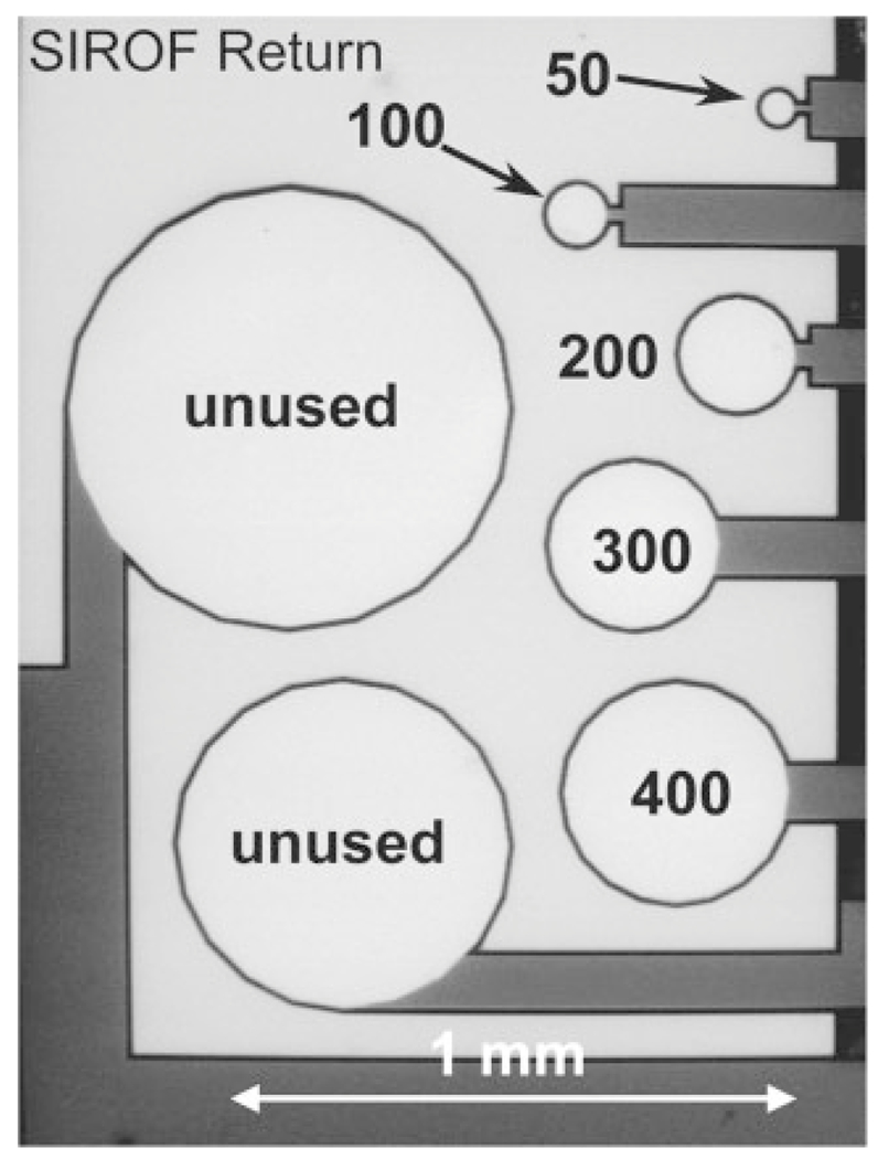
SEM image of a seven-electrode cluster identifying the five electrode sizes (50–400 μm diameter) evaluated in the present study. The light areas in the image are SIROF. Two unused SIROF sites and the approximately rectangular unused SIROF return site surrounding the charge-injection electrodes are also indicated.
The MEAs were fabricated by spinning a 12 μm thick base coating onto a 100 mm-diameter silicon wafer using HD Microsystems PI-2611 polyimide, which was subsequently cured in a N2-purged vacuum oven at 350°C. A three-layer metallization, comprised of two titanium adhesion layers and a gold conductor (Ti/Au/Ti) was deposited on the polyimide by physical vapor deposition and patterned using a lift-off resist process. The Ti and Au films were 50 nm and 1.5 μm thick, respectively. A three millimeter-thick polyimide overlayer was then spun onto the metallized polyimide and cured at 350°C. Electrode sites and contact pads were formed by patterning the wafer with photoresist and exposing the underlying metallization by O2 reactive ion etching (RIE) through the polyimide overlayer. The wafer was then re-patterned with photoresist to expose only the electrode sites, which were coated with SIROF by reactive DC sputtering from an iridium metal target using deposition conditions described previously.29 A reactive gas mixture of Ar, O2, and H2 was employed to produce SIROF with a mixed Ir3+/Ir4+ reduction-oxidation state. The SIROF extends slightly onto the polyimide lip at the electrode circumference to prevent underlying metallization at the charge-injection site from being exposed directly to the test electrolytes. The degree of extension is independent of film thickness. The wafers were again patterned with photoresist, and O2 RIE used to form the perimeter of each individual array by etching through the combined 15-μm thickness of the polyimide layers. After soaking in water, the individual arrays are readily removed from the silicon wafers. The thickness of the SIROFs investigated ranged from 200 to 1300 nm. The as-deposited SIROF was characterized by scanning electron microscopy (SEM) using an FEI Quanta 200 and film thickness was determined from measurements of SIROFs on glass witness samples using a Dektak surface profilometer.
Electrochemical Measurements
Electrical contact to the arrays was made with a custom-built clamp that held the contact pads at the proximal end of the array against raised gold bumps on a circuit board. A ribbon cable connector mounted on the circuit board then connected to external instrumentation. The SIROFs were characterized electrochemically by cyclic voltammetry (CV) and electrochemical impedance spectroscopy (EIS). Two electrolytes were employed for the study: an Ar-deaerated, phosphate-buffered saline (PBS) having a composition of 126 mM NaCl, 22 mM NaH2PO4–7H2O and 81 mM Na2HPO4–H2O at pH 7.2–7.4, and an inorganic model of interstitial fluid (model-ISF) having a composition of NaCl 110 mM, NaHCO3 28 mM, KHCO3 7.5 mM, Na2HPO4–7H2O 2 mM, and 0.5 mM each of NaH2PO4–H2O, MgSO4, MgCl2, and CaCl2.30 For the model-ISF, a pH of 7.4 was maintained by a gentle flow of 5%CO2 6%O2 89%N2 gas through the electrolyte. Measurements in PBS were made at room temperature, whereas measurements in model-ISF were made at 37°C. All electrochemical measurements were made in a three-electrode cell using a large-area platinum counterelectrode and a Ag|AgCl (3M KCl) reference electrode. All potentials are reported with respect to Ag|AgCl.
Slow sweep rate CV measurements (50 mV/s) between potential limits of −0.6 and 0.8 V in PBS were used to calculate cathodal charge storage capacities (CSCc). The CSCc estimates the total amount of iridium oxide deposited on the substrate and is determined from the time integral of the negative current during a full CV cycle at a sweep rate of 50 mV/s.2 The EIS measurements were made in model-ISF over a 0.05–105 Hz frequency range using a 10 mV rms sinusoidal excitation voltage about a fixed potential between −0.6 and 0.8 V. The CV and EIS measurements were made with Gamry PC4 or PC3 potentiostats and vendor supplied software. Prior to electrochemical measurements all SIROF films were subjected to CV cycling in PBS to rehydrate the films following the final steps in the array fabrication process. Typically, a stable CV response was obtained after 3 hours equal to 193 cycles.
Charge-injection limits were determined from potential transients measured during current pulsing in model-ISF at 37°C. Two current waveforms employing different charge-balancing strategies were used. With both waveforms, the microelectrode potential in the interpulse period was positively biased relative to the Ag|AgCl reference electrode. With one waveform, the current pulses were delivered as charge-balanced, biphasic pairs at a frequency of 50 pulses/s, with the leading phase always cathodal. The pulse pairs were asymmetric with the cathodal phase delivered at a higher current and shorter pulsewidth than the anodal phase. The rationale for employing asymmetric current pulsing when using a positive bias with iridium oxide has been detailed previously.31 Asymmetries in the waveforms, defined as the ratio of the anodal-to-cathodal pulsewidth (ta:tc), from 1:1 to 8:1 were investigated. The cathodal and anodal phases were separated by a 20 μs interphase delay (td), during which the applied current was zero. The maximum cathodally driven electrochemical potential excursion (Emc) was taken as the voltage recorded in the interphase period, approximately 10 μs after the end of the cathodal pulse. Similarly, the maximum anodally driven potential excursion (Ema) was taken as the voltage 10 μs after the end of the anodal pulse. The advantage of determining Emc and Ema in this manner is the absence of an ohmic contribution to the measured potential.32 An example of an asymmetric current waveform and resulting voltage transient is shown in Figure 2. The maximum charge that could be injected with the SIROF was defined as that which polarized the electrode to either Emc= −0.6 or Ema= +0.8 V, whichever potential was reached first. The potential transients were recorded after a steady-state response was obtained, usually within 30 s after the pulsing was initiated. Interpulse potential bias levels (Eipp) from 0.0 to 0.7 V were investigated.
Figure 2.
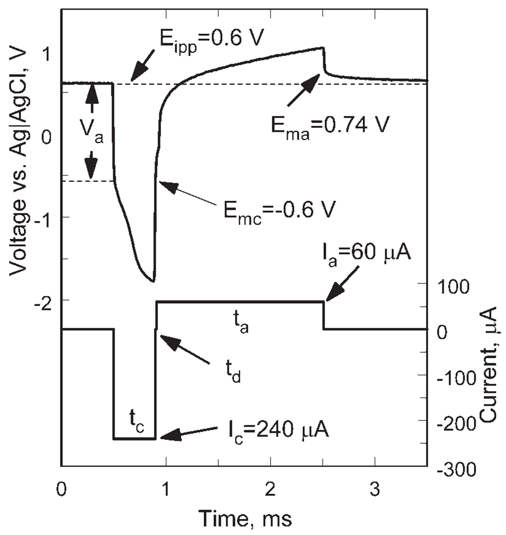
Representative voltage transient of a SIROF electrode in response to a biphasic, asymmetric current pulse with a 240 μA cathodal-first leading phase and a 60 μA anodal phase (tc = 0.4 ms, ta = 1.6 ms, td = 20 μs).
In the second strategy, monophasic cathodal current pulses were delivered with a positively biased electrode using the compliance-limited pulsing method proposed by Troyk and coworkers.33 Charge-balance is obtained by reestablishing the bias potential in the interpulse period using an anodic recharge current that is sufficient to establish the bias within a few milliseconds of the cathodal pulse. The stimulator is designed to limit the recharge current so that the microelectrode cannot be polarized more positively than the 0.8 V water oxidation limit observed with AIROF or Pt electrodes. It is also possible with the compliance limited strategy to avoid polarizing the electrode more negative than a preset negative driving voltage, such as the reduction potential for water, although this aspect of compliance-limited charge delivery was not employed in the present study. An example of the voltage and current waveforms for the compliance-limited pulsing is shown in Figure 3 for a 300 nm SIROF (GSA = 1960 μm2) pulsed at Ic = 248 μA, tc = 0.4 ms, and td = 0.1 ms. The Emc is −0.6 V, resulting in a charge-injection capacity of 99 nC/phase (5.1 mC/cm2) for this electrode. The anodic recharge current (Ia) peaked at 72 μA and is shown decreasing in magnitude as the electrode voltage approaches the 0.6 V Eipp. The monophasic waveform was used to measure the charge-injection capacity of SIROF at three thickness levels (240, 500, 770 nm) and at two pulse widths (0.4 and 1 ms). For the monophasic pulsing, the criterion for maximum charge-injection limit was that the electrode should not be polarized negative of the water reduction potential (−0.6 V).
Figure 3.
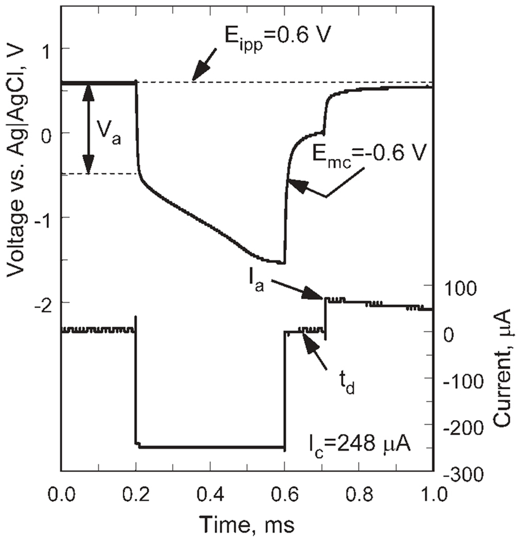
Representative voltage transient of a SIROF electrode in response to a monophasic, 256 μA cathodal current pulse (pulse width = 0.4 ms) using a positive potential bias of 0.6 V (Ag|AgCl).
The current required to sustain a positive bias in the absence of pulsing was measured chronoamperometrically by holding the electrode at a fixed potential and recording the current response over 1500 s at a measurement frequency of 1 Hz. The steady state current was taken as the average of the last 300 data points in the record. The bias current was measured at potentials from 0 to 0.7 V in 0.1 V increments.
RESULTS
SIROF Surface Morphology and Charge Storage Capacity
SIROF morphology is shown in Figure 4 for films with a thickness of 240, 500, and 770 nm. The 770 nm SIROF is comprised of densely packed nodules that are approximately circular with a diameter of 200–400 nm. For the 500 nm SIROF, the nodular surface is less developed but still apparent, whereas for the 240 nm SIROF, the surface morphology is barely observable. Representative CVs in PBS for these SIROFs are shown in Figure 5. Averaged over one array, the CSCc of the 50 μm diameter SIROF sites increased with thickness from 78 ± 2 mC/cm2 (n = 4) at 240 nm and 133 ± 6 mC/cm2 (n = 4) at 500 nm to 194 6 2 mC/cm2 (n = 3) at 770 nm; CSCc was nearly linear with thickness over this range. As observed with AIROF,32 the CSCc measured in model-ISF at room temperature is less than that measured in PBS, being about 20% less for the 240 nm SIROF. The lower CSCc is due to the reduced buffering capacity of the carbonate-based model-ISF compared with the phosphate buffer in PBS, which is also present at much higher concentrations than is found physiologically.
Figure 4.
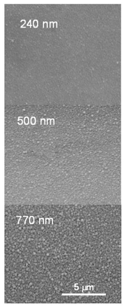
SEM images of the surface morphology of 240, 500, and 770 nm thick SIROF.
Figure 5.
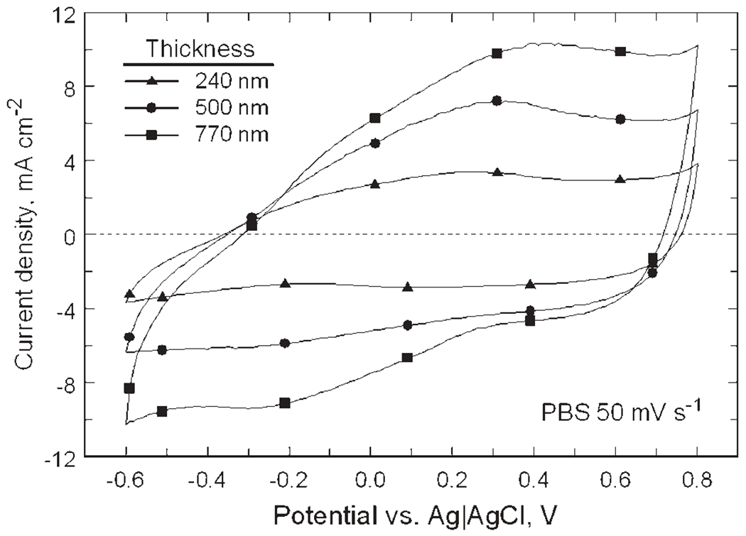
Cyclic voltammograms of SIROF at 50 mV/s sweep rate in PBS as a function of thickness. The corresponding CSCc’s are 78 mC/cm2 (240 nm), 133 mC/cm2 (500 nm), and 194 mC/cm2 (770 nm).
Qualitatively, SIROF exhibits good adhesion. Coatings ranging in thickness from 200–1300 nm deposited with a titanium adhesion layer on glass slides remained adherent when challenged by snap-pull and slow-pull tape tests. For all SIROF thickness levels, the tape adhesive remained as residue on the film, a phenomenon often observed when tape testing porous but adherent films. Thin SIROF (≤300 nm) exhibits good abrasion on glass substrates, although thicker films are marred and can be partially removed when rubbed with a pencil eraser.
Potential Limits for SIROF Stability
SIROF electrodes with a diameter of 50 μm were investigated by CV in model-ISF at a sweep rate of 50 mV/s. The positive and negative limits of the triangular potential waveform were expanded in 50 mV increments from −0.6 and 0.8 V in the negative and positive directions, respectively until evidence of water electrolysis or other non-reversible processes at each limit was observed. At a potential of 1.05 V, a sharp increase in anodic current occurs due to the onset of water oxidation. Water reduction was observed at a potential of −1.05 V, and it was accompanied by SIROF delamination from the underlying metallization after several CV cycles to this negative limit. To avoid delamination in subsequent studies, the maximum negative potential was limited to −0.9 V. Repetitive cycling between limits of −0.9 and 1.05 V produced some changes in the SIROF CVs as shown by the comparison in Figure 6 using a 1300 nm thick, 50 μm diameter SIROF electrode of the responses before and after 393 cycles between these voltage limits at a rate of 50 mV/s. At potentials more negative than about −0.25 V, there is a loss of charge capacity as indicated by a decrease in cathodic current (hatched area, Figure 6). This loss of cathodic charge capacity is reflected in an overall decease in anodic current, which occurs broadly over a −0.6 to 1.0 V potential range on the positive scan. The principal reduction and oxidation peaks, at −0.2 and 0.5 V, respectively, were also more pronounced after cycling. There was no visible indication of delamination or the emergence of new peaks in the CV response, such as are observed with over-pulsed AIROF,17 that would indicate degradation of the SIROF. Because previous assessments of the charge-injection properties of iridium oxide and platinum-based electrodes have used −0.6 and 0.8 V as potential limits for CV and as allowable maximum potential excursions during current pulsing, CVs over this more limited potential range were also evaluated. A comparison of the SIROF CV response between −0.6 and 0.8 V, taken before and after the 393 cycle −0.90/1.05 V challenge, is shown in Figure 7. Similar to the CVs at the more expanded potential range, the SIROF exhibits a reduced cathodic charge capacity at negative potentials and more pronounced Ir3+/Ir4+ redox peaks after cycling. The CSCc of the SIROF at the −0.6/0.8 V limits decreased modestly from 177 to 169 mC/cm2 after the 393 cycles. The magnitude of the CSCc is noteworthy, being considerably higher than that typically obtained with AIROF charge-injection coatings, which are prone to delamination at CSCc levels much above 80 mC/cm2. Following the 393 cycle challenge, the SIROF was cycled for an additional 100 cycles between limits of −0.6 and 0.8 V without changes in the CV response from that shown in Figure 7. The same potential dependence for water electrolysis and SIROF delamination was also observed for 400 nm thick films with diameters of 50 and 400 μm.
Figure 6.
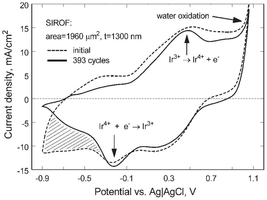
Changes in the CV response of a 1300 nm thick SIROF after 393 cycles at 50 mV/s between −0.9 V and 1.05 V versus Ag|AgCl.
Figure 7.
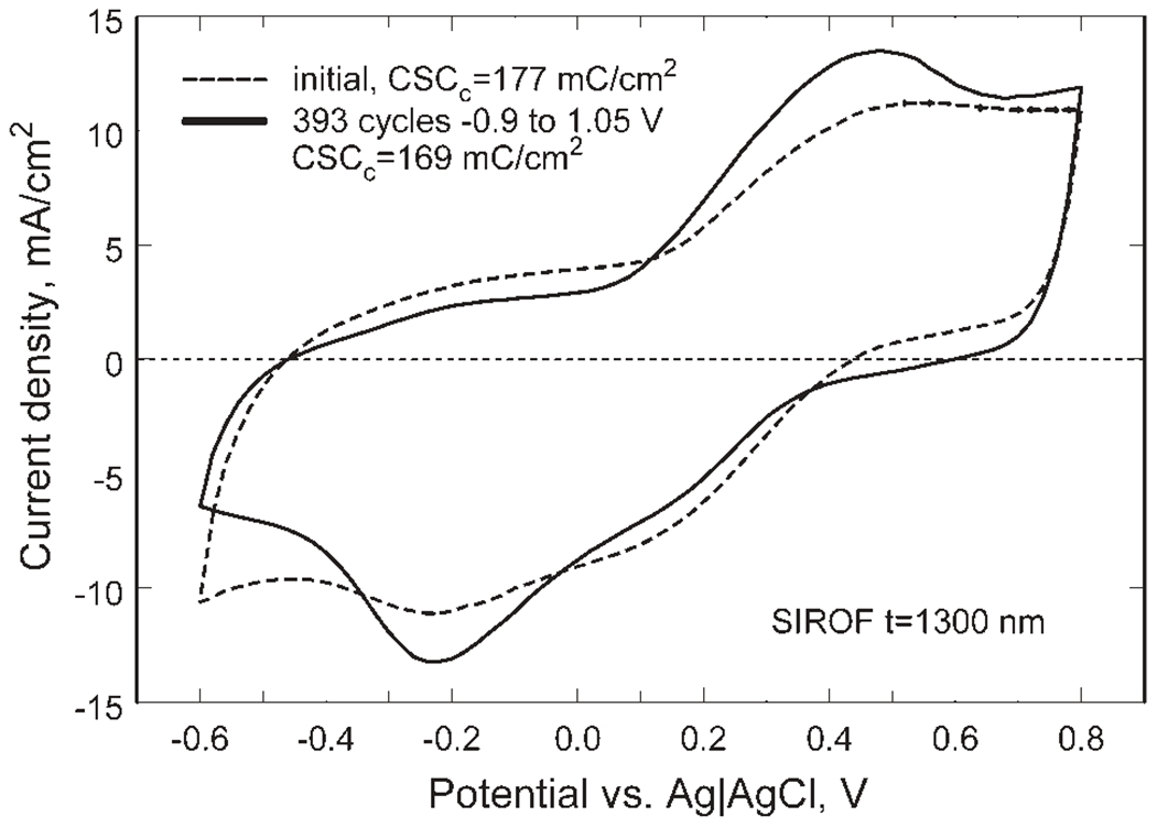
Changes in the CV response of a 1300 nm thick SIROF after 393 cycles at 50 mV/s between −0.6 V and 0.8 V versus Ag|AgCl.
SIROF Impedance
The impedance modulus of SIROF in model-ISF is shown in Figure 8 as a function of film thickness, with an uncoated gold site included for comparison. Even for the 200 nm SIROF, the impedance compared with the uncoated electrode site is reduced by more than a factor of 10 over the frequency range typically used for neural recording (102–104 Hz). Increasing the SIROF thickness to 1300 nm results in a further decrease in impedance, most notably at frequencies below 100 Hz. The SIROF impedance response is typical of that observed with other iridium oxides or high surface area electrodes, such as f-TiN, exhibiting resistive behavior dominated by electrolyte conductivity at high frequencies and capacitive-like behavior at low frequencies were charge transfer reactions dominate.
Figure 8.
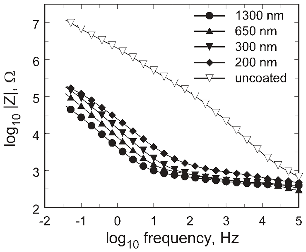
Impedance magnitude as a function of frequency for 200–1300 nm thick SIROF. For clarity, only every fourth data point is indicated with a symbol.
Charge-Injection Limits
The charge-injection capacity of the SIROF was measured in model-ISF (37°C) as a function of bias voltage, pulse width, waveform asymmetry, SIROF thickness, and electrode area. The conservative potential limits of −0.6 and 0.8 V were used to define the charge-injection capacity and allow direct comparison with the reported charge-injection capacities of AIROF and PtIr metal electrodes.2,34,35
Bias and Waveform Asymmetry.
The charge-injection limits of a 300 nm thick, 50 μm diameter SIROF electrode are shown in Figure 9 as a function of bias and waveform asymmetry for biphasic pulses with a 0.4 ms leading cathodal phase and pulse frequency of 50 Hz. These are representative data from a single electrode. The maximum charge-injection capacity for this electrode is 4.7 mC/cm2 obtained at a 0.6 V bias and waveform asymmetry of 4:1. The charge was cathodally limited, meaning that the −0.6 V negative limit was reached before the 0.8 V positive limit. Filled and open symbols in Figure 9 represent cathodally and anodally limited charge-injection limits, respectively. The dependence on interpulse bias and waveform asymmetry is similar to that obtained with AIROF, which also exhibits a maximum charge-injection capacity at a 0.6 V bias.31 The SIROF charge-injection limits were notably less sensitive to interpulse bias than those of AIROF, which decrease to <10% of the maximum charge-injection capacity as the bias is reduced from 0.6 to 0 V. For SIROF, the charge capacity shows a 50% decrease over the same bias range.
Figure 9.
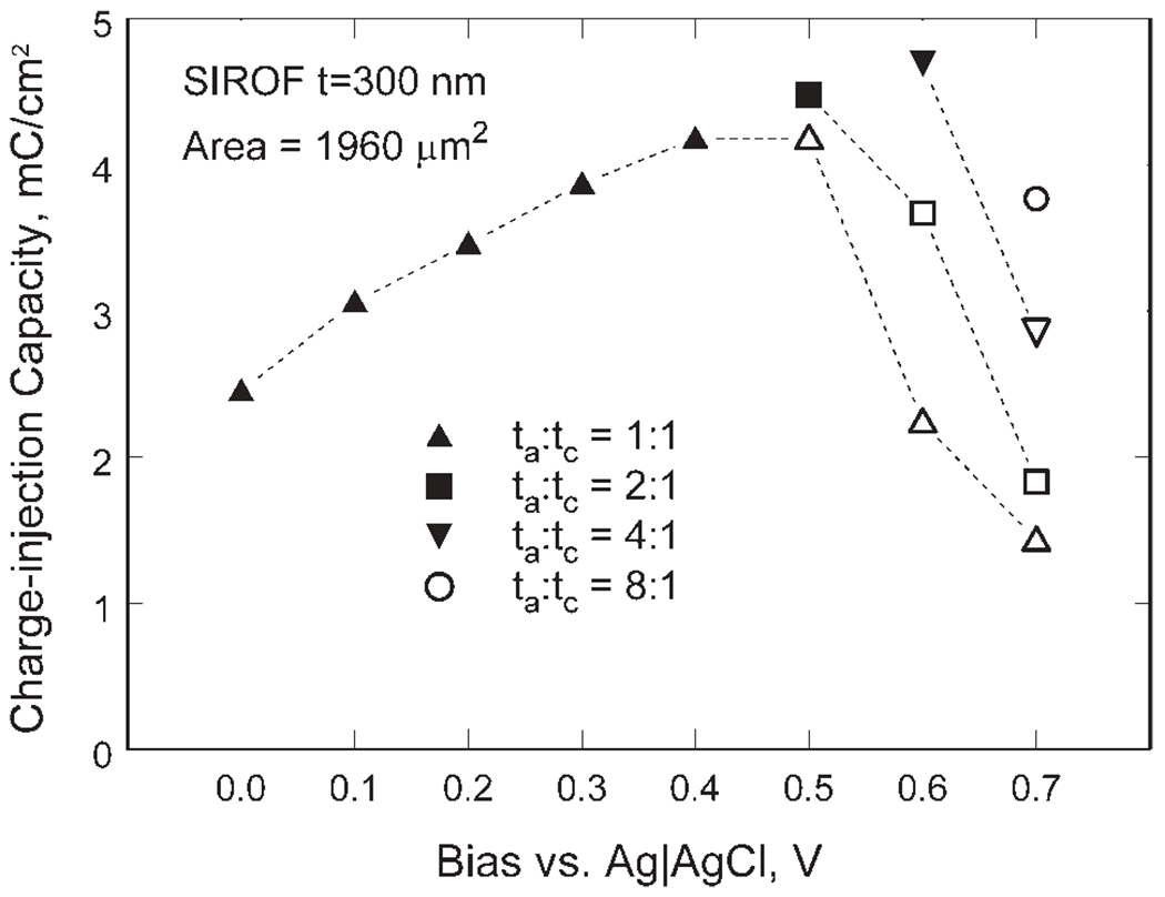
Charge-injection capacity of a 300 nm SIROF in response to biased, biphasic asymmetric current pulses showing the dependence on bias level (Eipp in Figure 3) and waveform asymmetry (ta:tc). Filled and open symbols represent cathodally and anodally limited charge-injection limits, respectively.
Pulse Width.
The dependence of SIROF charge-injection capacity on pulse width for a 300 nm thick, 50 μm diameter electrode is shown in Figure 10. Charge-injection capacities of AIROF and PtIr microelectrodes with a similar area from Cogan et al2 are included for comparison. Each SIROF data point is the mean of four 50-μm diameter sites from one array and the error bars are the standard deviation of the mean. As expected, the SIROF charge-injection capacity increases monotonically from 3.54 to 7.64 mC/cm2 as the pulse width is increased from 0.2 to 1.0 ms. The same pulse width dependence was observed for all SIROF thickness levels investigated.
Figure 10.
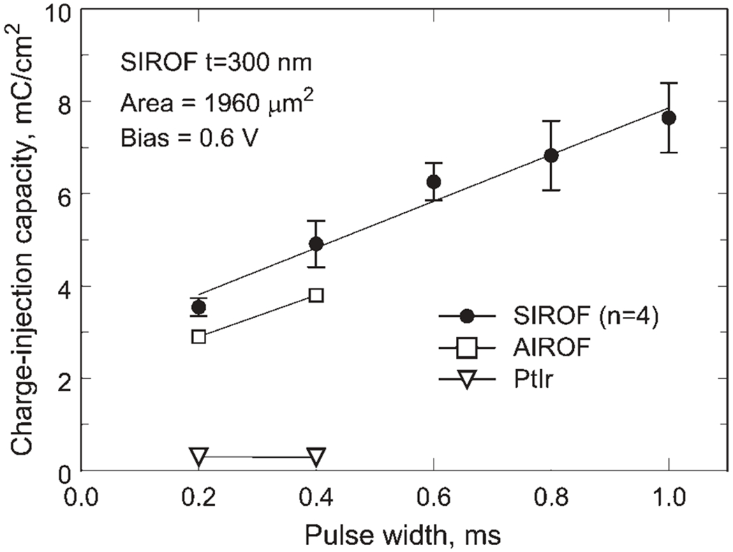
Charge-injection capacity of a 300 nm SIROF as a function of pulse width. Similar sized AIROF and PtIr microelectrode data from Cogan et al2 are included for comparison.
SIROF Thickness.
SIROF charge-injection capacity did not vary significantly in a comparison of three film thicknesses of 240 nm (n = 4), 500 nm (n = 4), and 770 nm (n = 3) for 50 μm diameter electrodes subjected to 400 μs pulses at a bias of 0.6 V versus Ag|AgCl (p > 0.05, one way ANOVA). Similar results were obtained for these electrodes with 1 ms pulse widths, although the 500 nm SIROF exhibited a slightly lower, but statistically significant, Qinj than either the 240 nm or 770 nm SIROF (p = 0.003, one way ANOVA). For the three pooled thickness levels, the Qinj for the 0.4 ms and 1.0 ms pulse widths was 5.2 ± 0.3 and 8.9 ± 0.6 mC/cm2 (mean ± SD), respectively. The lack of thickness dependence of Qinj during current pulsing contrasts with the much lower current density CV measurements, in which CSCc exhibits a linear dependence on SIROF thickness.
Electrode Area.
The geometry and area of an electrode can affect charge-injection capacity measurements because of the non-uniform current distribution which localizes the charge-injection reactions to the perimeter of the electrode. With short duration current pulses, the central regions of the electrode are underutilized and a lower overall charge-injection density results. The charge-injection capacity as a function of area is shown in Figure 11 as an average of five films with a thickness range of 200–1000 nm. For the average response, the charge injection capacity decreased from 4.4 ± 0.8 to 1.9 ± 0.2 mC/cm2 as the electrode area increased from 1960 to 125,600 μm2. The charge per phase is still much higher for the larger area films, increasing from 0.09 ± 0.02 to 2.4 ± 0.3 μC/ph for the same increase in area. The data are shown averaged over a range of thickness levels to emphasize the dominance of the electrode area dependence over that of the SIROF thickness when measuring Qinj by voltage transient measurements at least for the thickness range investigated.
Figure 11.
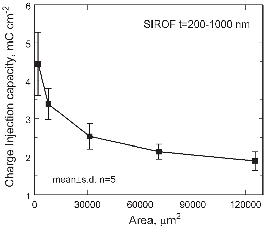
SIROF charge-injection capacity as a function of electrode area. Each data point is the average of five thickness levels at each area (mean ± SD).
Bias Maintenance Current
Applying a positive bias to increase the cathodal charge-injection capacity of the SIROF requires a sustained DC current in the interpulse period to maintain the iridium oxide at a non-equilibrium potential. The current density is shown in Figure 12 as a function of bias potential and thickness for 400 μm diameter electrodes (n = 4). The current density necessary to sustain a bias increases significantly at potentials more positive than 0.4 V and also increases with SIROF thickness. At a bias of 0.6 V, the current density increases from 0.46 ± 0.23 μA/cm2 to 10.2 ± 1.7 μA/cm2 as SIROF thickness increases from 200 to 1000 nm. The corresponding currents are small, ranging from 0.58 ± 0.29 (200 nm) to 12.8 ± 2.1 nA (1000 nm). For a 300 nm thick, 50 μm diameter SIROF electrode, the current density required to sustain a 0.6 V bias was 2.2 ± 0.5 μA/cm2 with a corresponding current of 0.04 ± 0.01 nA. The nature of the chemical reaction that reduces Ir4+, thus requiring the anodic current to sustain a positive bias, is not clearly understood but the bias currents increase with increasing buffering capacity of the electrolyte in which they are measured.
Figure 12.
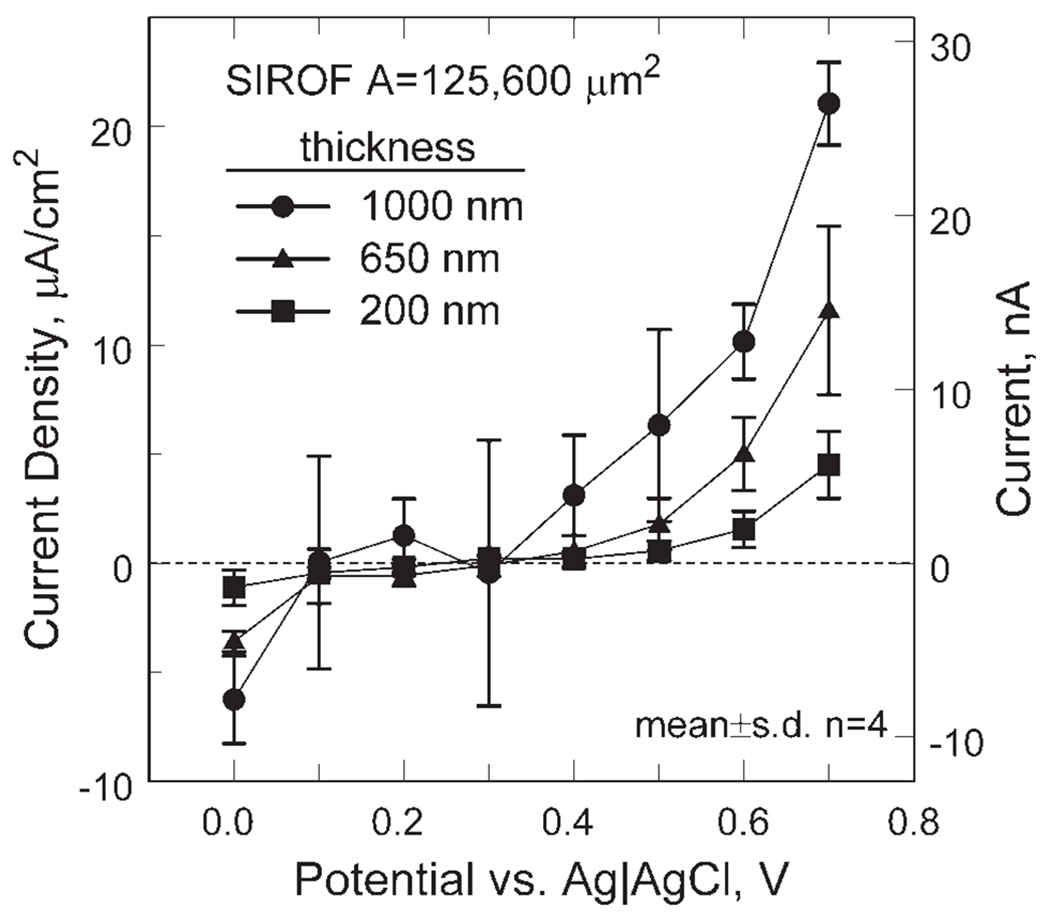
Current necessary to sustain a non-equilibrium interpulse bias in model-ISF for three SIROF thickness levels.
DISCUSSION
There are some notable differences between SIROF and the more familiar AIROF electrode coatings. Previous reports have identified a CSCc limit for AIROF of about 80 mC/cm2 beyond which continued activation of iridium to higher CSCc levels results in delamination of the AIROF, presumably due the large volume changes associated with the ingress and egress of counterions and water during the oxidation and reduction of the AIROF while cycling.34 SIROF coatings, however, have been deposited to a CSCc of 180 mC/cm2 and remain stable during CV cycling between −0.6 V and 0.8 V (50 mV/s). The ability to employ thicker SIROF films may provide some advantage in reducing electrode impedance for neural recording, as shown in Figure 8. An optimum SIROF thickness for charge-injection for stimulation was not identified. However, SIROF with a thickness in the 200–1300 nm range provides charge-injection comparable with AIROF and substantially greater than that possible with PtIr or high surface area titanium nitride.2,11 The observation that the charge-injection capacity of SIROF is independent of thickness for levels greater than 200 nm is consistent with the charge-injection behavior of AIROF. Measurements by Beebe and Rose,34 using 0.2 ms pulses and several different controlled current waveforms revealed an AIROF charge-injection capacity that was independent of CSCc for levels greater than 30–40 mC/cm2. The CSCc of the SIROF at all thickness levels in the present study exceeded 50 mC/cm2.
There is some debate as to the details of the reduction and oxidation reactions occurring in iridium oxide films at near-neutral pH. Electrode reactions that rely on the H+ or OH− ion as the counterion for electroneutrality exhibit a pH-dependent potential of −59 mV/pH-unit for a one-electron reaction, the so-called Nernstian response. In the present study, the equilibrium rest potential of SIROF was investigated in the pH 6–9 range. A near-Nernstian pH dependent potential of −58 mV/pH-unit (95% CI −55/−61, n = 4) was observed suggesting that either H+ or OH− is the predominant counterion in the sputtered film. A similar −55 to −59 mV/pH-unit response for SIROF has been reported.36,37 Based on mirage detection studies, Bardin et al37 identified OH− as the counterion over a 3–11 pH range, suggesting a counterion expulsion from SIROF during reduction and counterion insertion during oxidation. In contrast, a super-Nernstian behavior has been recognized with AIROF, which exhibits a −70 to −90 mV/pH-unit dependence on the potential of the principal Ir3+/Ir4+ redox reaction.38 AIROF electrodes characterized in the present study for comparison with SIROF exhibited a −68 mV/pH-unit (95% CI −65/−71, n = 6) dependency. The super-Nernstian response requires that either counterions besides H+ and OH−, or a combination of H+ and OH− are involved in the reduction and oxidation processes. Cations, such as Li+ and Na+, as well as small anions have also been identified as co-counterions with H+ or OH− in AIROF.38 The difference in pH response between SIROF and AIROF may be related to the differences in the density of the films. AIROF has a density of <2 g/cm3, less than 20% of the density of crystalline IrO2 (ρ = 11.2 g/cm3), with an open, hydrated nano-porous structure that should be conducive to ion transport. Although the density of the SIROF investigated in the present work was not measured, SIROFs are typically much denser, about 7.8 g/cm3 when fully hydrated,21 and consequently we expect ion transport in the SIROF to be less facile, favoring smaller counterions.
CONCLUSIONS
Thin films of sputtered iridium oxide have charge-injection properties similar to activated iridium oxide, exhibiting a bias-dependent charge-injection capacity of about 5 mC/cm2 using 0.4 ms cathodal current pulses at a bias of 0.6 V (Ag|AgCl). Adherent sputtered films with cathodal CSCs over 100 mC/cm2 and film thickness over 1000 nm can be deposited onto gold substrates without stress-induced delamination. The sputtered iridium oxide exhibits a near-Nernstian 59 mV/pH-unit response suggesting a less complicated single counterion (H+ or OH−) charge-injection reaction rather than the super-Nernstian response observed with AIROF. The SIROF can be deposited and patterned by conventional sputtering and photolithographic techniques, making it suitable as a low impedance recording or stimulation coating for flexible and rigid planar multielectrode arrays. These in vitro studies have also shown that SIROF is stable under moderately aggressive long-term pulsing in an inorganic model of interstitial fluid at 37°C. Further work is now required to determine the chronic in vivo properties and stability of SIROF coatings under long-term pulsing conditions in anticipation of their use in retinal prostheses.
Acknowledgments
Contract grant sponsor: Department of Veterans Affairs; Rehabilitation Research and Development Service; National Institutes of Health; Contract grant numbers: C4266-C, 5R44HL071395
REFERENCES
- 1.Merrill DR, Bikson M, Jefferys JGR. Electrical stimulation of excitable tissue: Design of efficacious and safe protocols J Neurosci Methods 2005;141:171–198. [DOI] [PubMed] [Google Scholar]
- 2.Cogan SF, Troyk PR, Ehrlich J, Plante TD. In vitro comparison of the charge-injection limits of activated iridium oxide (AIROF) and platinum-iridium microelectrodes. IEEE Trans Biomed Eng 2005;52:612–614. [DOI] [PubMed] [Google Scholar]
- 3.McCreery DB, Agnew WF, Bullara LA. The effects of prolonged intracortical microstimulation on the excitability of pyramidal tract neurons in the cat. Ann Biomed Eng 2002;30: 107–119. [DOI] [PubMed] [Google Scholar]
- 4.McCreery DB, Yuen TGH, Bullara LA. Chronic microstimulation in the feline ventral cochlear nucleus: Physiologic and histologic effects, Hearing Res 2000;149:223–238. [DOI] [PubMed] [Google Scholar]
- 5.McCreery DB, Lossinsky A, Pikov V, Liu X. Microelectrode array for chronic deep-brain microstimulation and recording, IEEE Trans Biomed Eng 2006;53:726–737. [DOI] [PubMed] [Google Scholar]
- 6.Rizzo JF, Wyatt J, Loewenstein J, Kelly S, Shire D. Methods and perceptual thresholds for short-term electrical stimulation of human retina with microelectrode arrays. Invest Ophthalmol Vis Sci 2003;44:5355–5361. [DOI] [PubMed] [Google Scholar]
- 7.Humayun MS, Weiland JD, Fujii GY, Greenberg R, Williamson R, Little J, Mech B, Cimmarusti V, Van Boemel G, Dagnelie G, de Juan E. Visual perception in a blind subject with a chronic microelectronic retinal prosthesis. Vision Res 2003;43:2573–2581. [DOI] [PubMed] [Google Scholar]
- 8.Mahadevappa M, Weiland JD, Yanai D, Fine I, Greenberg RJ, Humayun MS. Perceptual thresholds and electrode impedance in three retinal prosthesis subjects. IEEE Trans Neural Syst Rehabil Eng 2005;13:201–206. [DOI] [PubMed] [Google Scholar]
- 9.Palanker D, Vankov H, Huie P, Baccus S. Design of a high-resolution optoelectronic retinal prosthesis. J Neural Eng 2005; 2:S105–120. [DOI] [PubMed] [Google Scholar]
- 10.Robblee LS, Lefko JL, Brummer SB. Activated Ir: An electrode suitable for reversible charge injection in saline. J Electrochem Soc 1983;130:731–732. [Google Scholar]
- 11.Weiland JD, Anderson DJ, Humayun MS. In vitro electrical properties for iridium oxide versus titanium nitride stimulating electrodes. IEEE Trans Biomed Eng 2002;49:1574–1579. [DOI] [PubMed] [Google Scholar]
- 12.Wang K, Fishman HA, Dai H, Harris JS. Neural stimulation with a carbon nanotube microelectrode array. Nano Lett 2006; 6:2043–2048. [DOI] [PubMed] [Google Scholar]
- 13.Ludwig KA, Uram JD, Yang J, Martin DC, Kipke DR. Chronic neural recordings using silicon microelectrode arrays electrochemically deposited with a poly(3,4-ethylenedioxy-thiophene) (PEDOT) film. J Neural Eng 2006;3:59–70. [DOI] [PubMed] [Google Scholar]
- 14.Zhou DM. Platinum electrode and method of manufacturing the same, US Patent 6,974,533, Dec 13, 2005.
- 15.Schmidt EM, Bak MJ, Hambrecht FT, Kufta CV, O’Rourke DK, Vallabhanath P. Feasibility of a visual prosthesis for the blind based on intracortical microstimulation of the visual cortex. Brain 1996;119:507–522. [DOI] [PubMed] [Google Scholar]
- 16.Hambrecht FT. Visual prostheses based on direct interfaces with the visual system. Baillieres Clin Neurol 1996;4:147–165. [PubMed] [Google Scholar]
- 17.Cogan SF, Guzelian AA, Agnew WF, Yuen TG, McCreery DB. Over-pulsing degrades activated iridium oxide films used for intracortical neural stimulation. J Neurosci Methods 2004; 137:141–150. [DOI] [PubMed] [Google Scholar]
- 18.Meyer RD, Cogan SF, Nguyen TH, Rauh RD. Electrodeposited iridium oxide for neural stimulation and recording electrodes. IEEE Trans Neural Syst Rehabil Eng 2001;9:2–11. [DOI] [PubMed] [Google Scholar]
- 19.Robblee LS, Mangaudis Mj, Lasinsky ED, Kimball AG, Brummer SB. Charge injection properties of thermally-prepared iridium oxide films. Mat Res Soc Symp Proc 1986; 56:303–310. [Google Scholar]
- 20.McIntyre JDE, Peck WF, Nakahara S. Oxidation state changes and structure of electrochromic iridium oxide films. j Electrochem Soc 1980;127:1264–1268. [Google Scholar]
- 21.Kang KS, Shay JL. Blue sputtered iridium oxide films (blue SIROF’s). J Electrochem Soc 1983;30:766–769. [Google Scholar]
- 22.Klein JD, Clauson SL, Cogan SF. The influence of substrate bias on the morphology and charge capacity of RF-sputtered iridium oxide films. J Mater Res 1989;4:1505–1510. [Google Scholar]
- 23.Klein JD, Clauson SL, Cogan SF. Morphology and charge capacity of sputtered iridium oxide films. J Vac Sci Technol 1989;A7:3043–3047. [Google Scholar]
- 24.Aurian-Blajeni B, Boucher MM, Kimball AG, Robblee LS. Physicochemical characterization of sputtered iridium oxide. J Mater Res 1989;4:440–446. [Google Scholar]
- 25.Slavcheva E, Vitushinsky R, Mokwa W, Schnakenberg U. Sputtered iridium oxide films as charge injection material for functionalized electrostimulation. J Electrochem Soc 2004; 151:E226–E237. [Google Scholar]
- 26.Cogan SF, Plante TD, Ehrlich J. Sputtered iridium oxide films (SIROFs) for low-impedance neural stimulation and recording electrodes. Conf Proc IEEE Eng Med Biol Soc 2004;6:4153–4156. [DOI] [PMC free article] [PubMed] [Google Scholar]
- 27.Wessling B, Mokwa W, Schnakenberg U. RF-sputtering of iridium oxide to be used as stimulation material in functional medical implants. J Micromech Microeng 2006;16:S142–S148. [Google Scholar]
- 28.Winter JO, Cogan SF, Rizzo JF. Neurotrophin-eluting hydrogel coatings for neural stimulating electrodes. J Biomed Mater Res B Appl Biomater 2007;81:551–563. [DOI] [PubMed] [Google Scholar]
- 29.Klein JD, Clauson SL, Cogan SF. Reactive IrO2 sputtering in reducing/oxidizing atmospheres. J Mater Res 1995;10:328–333. [Google Scholar]
- 30.Selkurt EE. Body water and electrolyte composition and their regulation In: Selkurt EE, editor. Physiology, 3rd ed Boston: Little, Brown and Company; 1971. p 529–534. [Google Scholar]
- 31.Cogan SF, Troyk PR, Plante TD, Ehrlich J, Detlefsen DE. Potential-biased, asymmetric waveforms for charge-injection with activated iridium oxide (AIROF) neural stimulation electrodes. IEEE Trans Biomed Eng 2006;53:327–332. [DOI] [PubMed] [Google Scholar]
- 32.Cogan SF, Troyk PR, Ehrlich J, Gasbarro CM, Plante TD. The influence of electrolyte composition on the in vitro charge-injection limits of activated iridium oxide (AIROF) stimulation electrodes. J Neural Eng 2007;4:79–86. [DOI] [PubMed] [Google Scholar]
- 33.Troyk PR, Detlefsen DE, Cogan SF, Ehrlich J, Bak M, McCreery DB, Bullara L, Schmidt E. “Safe” charge-injection waveforms for iridium oxide (AIROF) microelectrodes. Conf Proc IEEE Eng Med Biol Soc 2004;6:4141–4144. [DOI] [PubMed] [Google Scholar]
- 34.Beebe X, Rose TL. Charge injection limits of activated iridium oxide electrodes with 0.2 ms pulses in bicarbonate buffered saline. IEEE Trans Biomed Eng 1988;35:494–495. [DOI] [PubMed] [Google Scholar]
- 35.Rose TL, Robblee LS. Electrical stimulation with Pt electrodes. VIII. Electrochemically safe charge injection limits with 0.2 ms pulses. IEEE Trans Biomed Eng 1990;37:1118–1120. [DOI] [PubMed] [Google Scholar]
- 36.Tarlov MJ, Semancik S, Kreider KG. Mechanistic and response studies of iridium oxide pH sensors, sensors and actuators, 1990;B1:293–297. [Google Scholar]
- 37.Bardin M, Loheac P, Petit M, Plichon V, Richard N. Electrochemical and mirage detection studies of sputtered iridium oxide films. New J Chem 1995;19:59–63. [Google Scholar]
- 38.Pickup PG, Birss VI. Chemical analysis of the ionic content of hydrous iridium oxide films J Electroanal Chem 1988;240: 171–183. [Google Scholar]


