Abstract
A wirelessly operated, minimally invasive retinal prosthesis was developed for preclinical chronic implantation studies in Yucatan minipig models. The implant conforms to the outer wall of the eye and drives a microfabricated polyimide stimulating electrode array with sputtered iridium oxide electrodes. This array is implanted in the subretinal space using a specially designed ab externo surgical technique that fixes the bulk of the prosthesis to the outer surface of the sclera. The implanted device is fabricated on a host polyimide flexible circuit. It consists of a 15-channel stimulator chip, secondary power and data receiving coils, and discrete power supply components. The completed device is encapsulated in poly(dimethylsiloxane) except for the reference/counter electrode and the thin electrode array. In vitro testing was performed to verify the performance of the system in biological saline using a custom RF transmitter circuit and primary coils. Stimulation patterns as well as pulse strength, duration, and frequency were programmed wirelessly using custom software and a graphical user interface. Wireless operation of the retinal implant has been verified both in vitro and in vivo in three pigs for more than seven months, the latter by measuring stimulus artifacts on the eye surface using contact lens electrodes.
Index Terms—: Electrode array, neural prosthesis, retinal implant, retinal prosthesis, subretinal, stimulation
I. Introduction
RETINAL prostheses are actively being developed by a number of groups worldwide [1]–[34]. These devices have been designed to restore lost visual function due to degenerative retinal diseases such as retinitis pigmentosa (RP) and age-related macular degeneration (AMD). These conditions cause a gradual loss of photoreceptor cells (which can cause blindness); yet, a substantial fraction of the neural pathways from the retina to the visual cortex remain functional despite the remodeling of the retinal neuronal architecture that results [35]. Existing treatments can perhaps slow the progress of these diseases, and no cure is available, but recent use of molecular genetic strategies has provided some restoration of vision in dogs and humans with RP [36]. There are approximately 1 700 000 affected individuals worldwide. AMD, meanwhile, is the leading cause of blindness in the developed world, with roughly 2 million affected patients in the U.S. alone. This number is expected to increase by 50% by the year 2020, as the population ages [37], [38].
Focal electrical stimulation of the remaining retinal ganglion cells in degenerated retinae can yield visual percepts that correlate with the strength and location of the stimuli [34], [39], [40]. It was also observed that threshold currents sufficient to elicit phosphenes were higher in subjects with retinal degenerations compared with normal subjects [30]. This collective body of research has made it clear that although severely impaired patients can see phosphenes upon stimulation even after years of blindness, they are fairly crude. There is a need to learn more effective stimulation strategies to improve the quality of artificial vision; hence, a chronically implantable device is required. As such, several research groups have endeavored to create the materials and methods to perform long-term implantations of retinal prostheses (e.g., [1], [2], [5], [6], [8], and [12]). In addition, regulatory bodies require substantial preclinical evaluation prior to obtaining permission to perform human clinical trials. This paper describes our own initial prosthetic design and the surgical procedures that we used to perform the necessary chronic animal implantations of our device.
A. Device Design Evolution
While early work in the vision restoration field focused on a cortical visual prosthesis [41]–[43], and efforts toward both this end and optic nerve stimulators continue to this day [44]–[49], the majority of the groups currently working in visual prosthetics are concentrating either on epiretinal (e.g., [4] and [10]) or subretinal (e.g., [7] and [16]) electrical stimulation, or less direct stimulation of the retina using a suprachoroidal or transscleral approach (e.g., [2], [5], and [12]). Our team’s approach for a number of years focused on epiretinal prosthesis design, culminating in several acute human surgical trials using comparable flexible, polyimide-based stimulating electrode arrays to those presented here [30], [31]. A number of practical factors, however, led to a decision to take an ab externo, subretinal surgical approach to chronic implantation of a wirelessly driven microstimulator (see Fig. 1). These factors are briefly summarized in Table I.
Fig. 1.

(Left) and (center) Graphical images of the ab externo approach for insertion of the electrode array. Inset: the array enters the subretinal space through a scleral flap, after a retinal bleb (center) has been raised to keep the delicate retina out of harm’s way. (Right) Photograph showing a polyimide guide strip entering the eye of a Yucatan minipig prior to insertion of the 16-μm-thick stimulating electrode array.
TABLE I.
Comparison Between Sub- and Epiretinal Visual Prosthesis Characteristics
| Sub-Retinal Visual Prosthesis Characteristics | Epi-Retinal Visual Prosthesis Characteristics |
|---|---|
| Ab externo surgical approach is minimally invasive | Requires chronic purs plana micro-cable entry into eye and/or intra-ocular electronic components |
| Heat-dissipating implanted electronic components can be mounted outside the sclera | Heat dissipation by intra-ocular prosthesis components may cause elevated temperature of the retina |
| Electrical stimulation is introduced closer to former photoreceptor sites and pre-synaptic cells | Electrical stimulation is introduced very close to remaining retinal ganglion cells |
| Uses specialized surgical tools and techniques that can be mastered by retinal surgeons with practice | Uses common vitreo-retinal surgical techniques, e.g. retinal tacks |
| Bulk of prosthesis is located against fatty tissue of eye orbit; device moves together with the eye | Has intra-ocular and/or intra-cranial components |
| Natural fixation of electrode array due to suction that holds the retina in place; retinal detachment due to surgical procedure resolves quickly, and array’s presence does not cause subsequent detachment. | Fixation of electrode array requires some form of retinal tack which can dislodge, e.g. due to trauma |
Most of these changes are related to surgical safety and biocompatibility. This transition affected many aspects of our engineering design, which is summarized in Fig. 2. The overall shape of the implant places the larger coil and electronics structures at a distance of approximately 1.5 cm from each other, so that the device may be implanted in the superior nasal and superior temporal quadrants of the ocular orbit. The middle section of the device contains only the polyimide host flexible circuit and a large reference/return electrode, and in the Yucatan minipig, this region is implanted underneath the superior rectus muscle. Only the flexible, 16-μm-thick polyimide array with iridium oxide (IrOx) stimulating electrodes enters the scleral flap, which is typically made 10 mm posterior to the limbus (i.e., the circumferential junction between the cornea and the sclera).
Fig. 2.
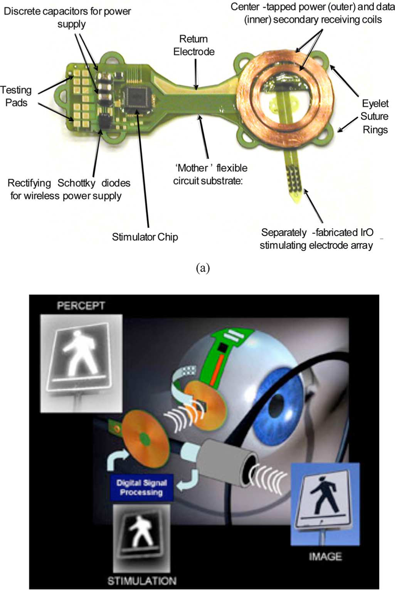
Engineering design of the subretinal microstimulator system. (a) Implanted components are built on a flexible, polyimide substrate. After assembly, the entire unit is coated in poly(dimethylsiloxane) except for the stimulating array and the current return electrode. The overall dimensions of the device are 12 mm × 31 mm. (b) Schematic diagram showing wireless operation of the visual prosthesis system. A camera (or external computer) and transmitter collect and then rebroadcast an image signal to the implanted stimulator chip, which is commanded to retransmit biphasic current pulses, in patterns corresponding to the desired image, to the stimulating electrode array located in the subretinal space.
The primary goal of this development effort was to demonstrate the feasibility of the ab externo, subretinal surgical approach by using conventional surface-mount electronic assembly techniques to create and implant a wirelessly driven microstimulator device. In passive life testing at 37 °C, our team determined that parylene-C-encapsulated implants could be exposed to saline environments for several months, until evidence of fluid leakage became apparent. Based on these experiments (which will be reported elsewhere), poly(dimethylsiloxane)-insulated devices were adopted for perfecting surgical techniques during animal surgical trials lasting several months. Meanwhile, our group has been developing next-generation, hermetically packaged devices that will ultimately be required for clinically relevant visual prosthetics.
The overall system design, outlined in Fig. 2(b), incorporates an external video capture unit (or computer) and a transmitter that sends image data wirelessly to the implanted portion of the device. There, a custom, application-specific stimulator IC (ASIC) translates the image information into biphasic current pulses of programmable strength, duration, and frequency to the electrode array. Since the optimal current level and stimulation protocols for providing restoration of usable visual percepts are not known, our design concept was to keep the “smart” image processing hardware and/or firmware in the external control unit, and for the implanted system to be as flexible and simple as possible.
II. Methods
A. Wireless Transmission System and Stimulator Chip
The implanted ASIC received data and power by inductive coupling on independent channels. The data were encoded by amplitude shift keying (ASK) on a 15 MHz carrier at 100 kb/s. The data include configuration values and stimulus current values. Real-time commands were sent to start and stop each stimulus pulse. The power was transmitted at 125 kHz and was rectified off-chip by two half-wave rectifiers to produce ±2.5 V, regulated by an off-chip 5.1 V Zener diode. An off-chip-resistor and capacitor provide a delay on power-up to allow the ASIC registers to reset to the proper state. A flowchart of the power and data transmission systems is shown in Fig. 3.
Fig. 3.
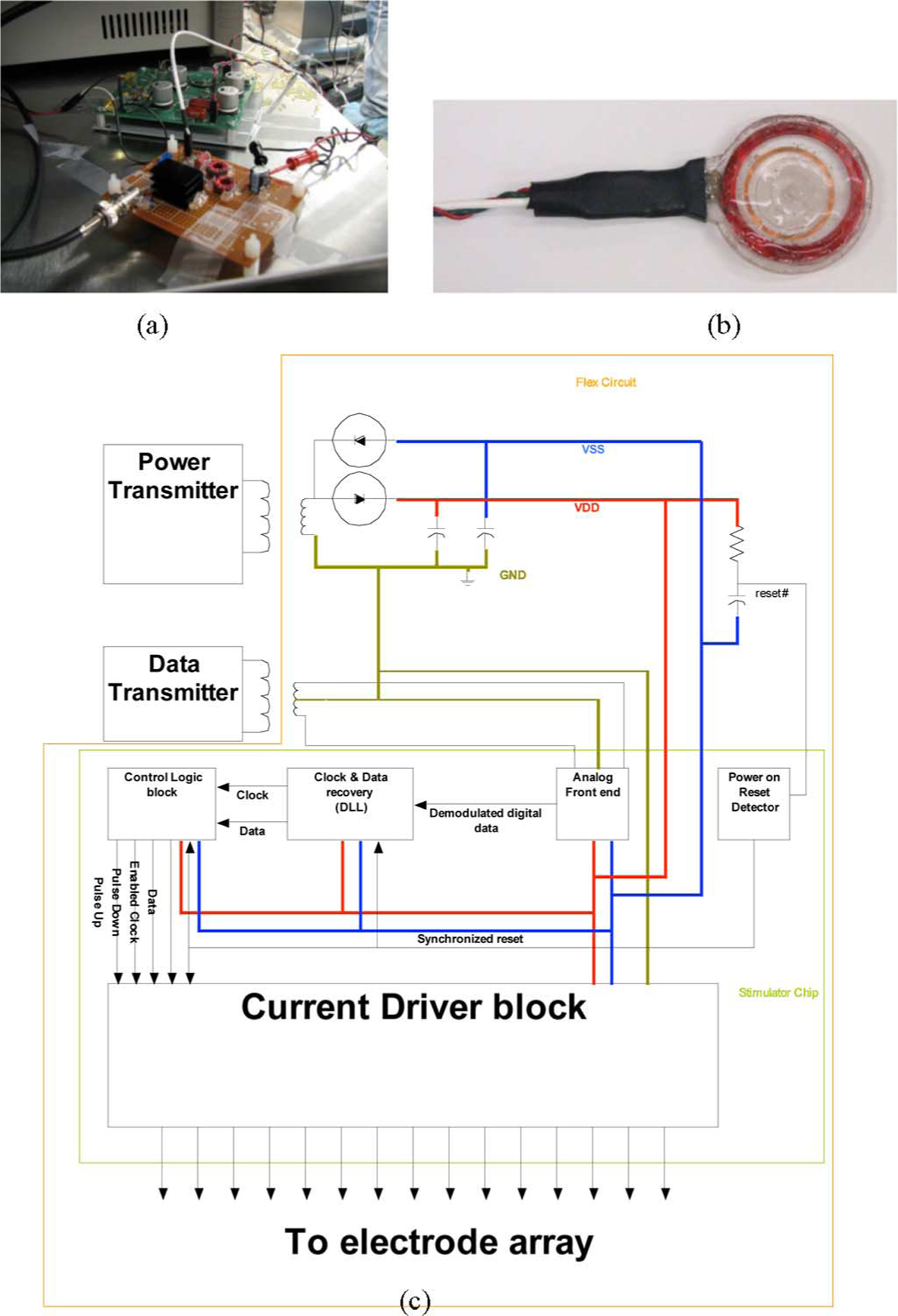
(a) Primary power and data transmitter circuits. (b) Primary transmitting coils encapsulated in poly(dimethylsiloxane). (c) Schematic diagram of the power and data inductive link-based transmission systems for the visual prosthesis. The implanted components are contained within the outer envelope, the rectifier and reset delay circuit are near the top, and the ASIC architecture is shown in the bottom half.
The ASK-encoded waveforms containing the image data are amplified by a separate class A power amplifier with a 40 V power supply, and sent to the primary data coil via a 25 Ω coaxial cable. A simple class D amplifier with a variable dual power supply generated the power waveforms; this was typically set between ±1.8 and ±2.8 Vp-p, but the supply resonated to achieve a peak primary coil voltage of over 50 V. The data frequency was chosen to allow the potential for higher data rates, while the power frequency was kept lower to improve efficiency by limiting losses. The primary and secondary data and power coil specifications are summarized in Table II. The secondary coil specifications derive from the maximum size of the implant that could fit on the temporal side of Yucatan minipig eye, while the primary coil specifications were chosen to maximize the field received at the secondary coil. In bench testing, we found a maximum transmission distance of approximately 22 mm when an average power of ~100 mW was input to the primary power coil. In biological saline, this was reduced to 20 mm, given the same input. With implanted devices, we achieved reliable data transmission over ~5–10 mm of separation between the coils. The differences were attributed to signal absorption by the orbital tissue and misalignment of the coil pairs due to the bone structure of the pigs.
TABLE II.
Implant Coil Parameters
| Coil | N | L | OD | ID | t |
|---|---|---|---|---|---|
| Power Primary | 47 | 142_H | 41.3mm | 33.7mm | 2.4mm |
| Dala Primary | 10 | 6.6_H | 27mm | 24mm | 0.1mm |
| Power Secondary | 47 | 34.3_H | 10.3mm | 8.3mm | lmm |
| Data Secondary | 12* | 1.34_H* | 7.6mm | 5.8mm | 0.5mm |
The secondary data coil was center-tapped; therefore, the number of turns per coil half and inductance per c half are listed.
The heart of the implant was a communication and stimulation ASIC, which contains 30 000 transistors in a 2.3 × 2.3 mm2 area and was fabricated in a 0.5 μm CMOS process (MOSIS, Irvine, CA) [50]. The chip drove 15 electrodes with 15 current-source drivers, of which 14 were capable of delivering up to 775 μA and one was capable of driving up to 1.55 mA. A third-order RC high-pass filter on the chip attenuated the power waveform and some of its harmonics before the input signal entered the data receiver circuit. A light micrograph showing the different sections of the ASIC is shown in Fig. 4.
Fig. 4.
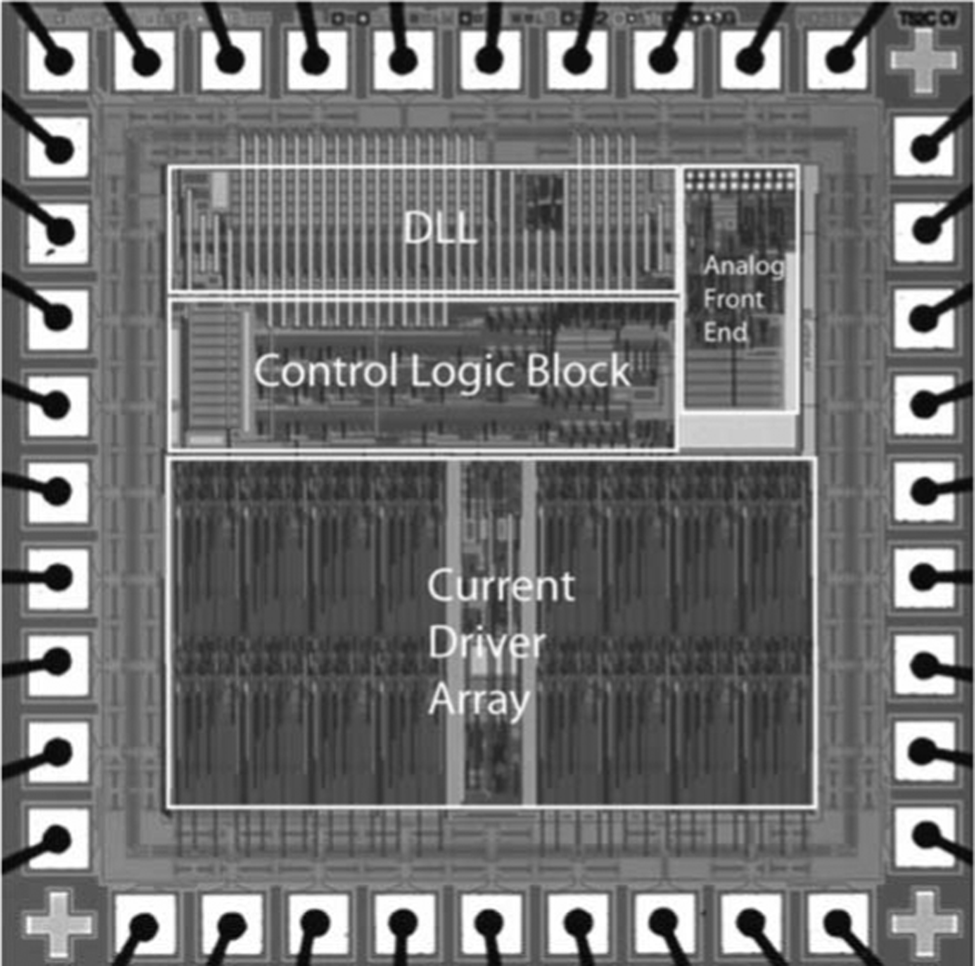
Micrograph of the custom stimulator chip used in these trials [50]. There are 15 output current drivers. Reconstruction of the input waveform is performed using a delay-locked loop.
B. Microfabrication and Assembly
The host flexible circuit onto which all of the prosthesis components were assembled was made by defining 50-μm-wide metal traces on the host polyimide substrate using a photolitho-graphic lift-off process. Since the implantation period for the animal surgical trials was of limited duration, these traces were made from a Cu/Ni/Au metallization commonly used in the microelectronics industry, and the coils were fabricated from Cu wire. In subsequent trials, our team developed fabrication techniques for flexible circuits using entirely biocompatible materials. In all cases, the subretinal electrode arrays were fabricated with materials that have previously been well tolerated during chronic implantations. Standard surface-mounted parts were used for all the off-chip power supply components, and these were assembled on the flex circuit using conventional wave soldering techniques. The ASICs were mounted by stud bumping with 75-μm-high Au bumps, followed by flip-chip die attachment to the host substrate. Stud bumping was also used for the flex-to-flex connections between the flex circuits and the electrode arrays. This approach proved to be prone to reliability problems, however, and in subsequent designs, we integrated the electrode array formation with the flex circuit fabrication process. Once the electrode array was attached and the stud bump connections were encapsulated in nonconductive epoxy, the power and data coils were added. The resulting assemblies were then coated in poly(dimethylsiloxane), with the exception of the active electrode array and the return/reference electrode on the host flex circuit.
The electrode arrays, shown in Fig. 5, were fabricated by first spin-coating and curing a 12-μm-thick base coating onto a 100-mm-diameter silicon wafer using Hitachi DuPont (HD) Microsystems PI-2611 polyimide. A three-layer metallization, comprising two titanium adhesion layers and a gold conductor layer (Ti/Au/Ti), was deposited on the polyimide by physical vapor deposition and patterned using a lift-off resist process. (The Ti and Au films were 50 nm and 1.5 μm thick, respectively.) A 3-μm-thick polyimide overlayer was spun over the metallized polyimide and cured at 350 °C. Electrode sites and contact pads were formed by patterning the wafer with photoresist and exposing the underlying metallization by O2 reactive ion etching (RIE). The wafer was then repatterned to expose only the electrode sites, which were then coated with 300 nm of a reactive dc-sputtered iridium oxide film (SIROF) from an iridium metal target [51]–[53]. A reactive gas mixture of Ar, O2, and H2 was employed to produce SIROF with a mixed Ir3+/Ir4+ reduction–oxidation state. The wafers were patterned a final time, and O2 RIE was used to define the perimeter of each individual array by etching through the combined 15 μm thickness of the polyimide layers. After soaking in water, the individual arrays were then readily removed from the silicon wafers for testing; typical yields of perfectly functional devices depended on array size, but exceeded 80%.
Fig. 5.
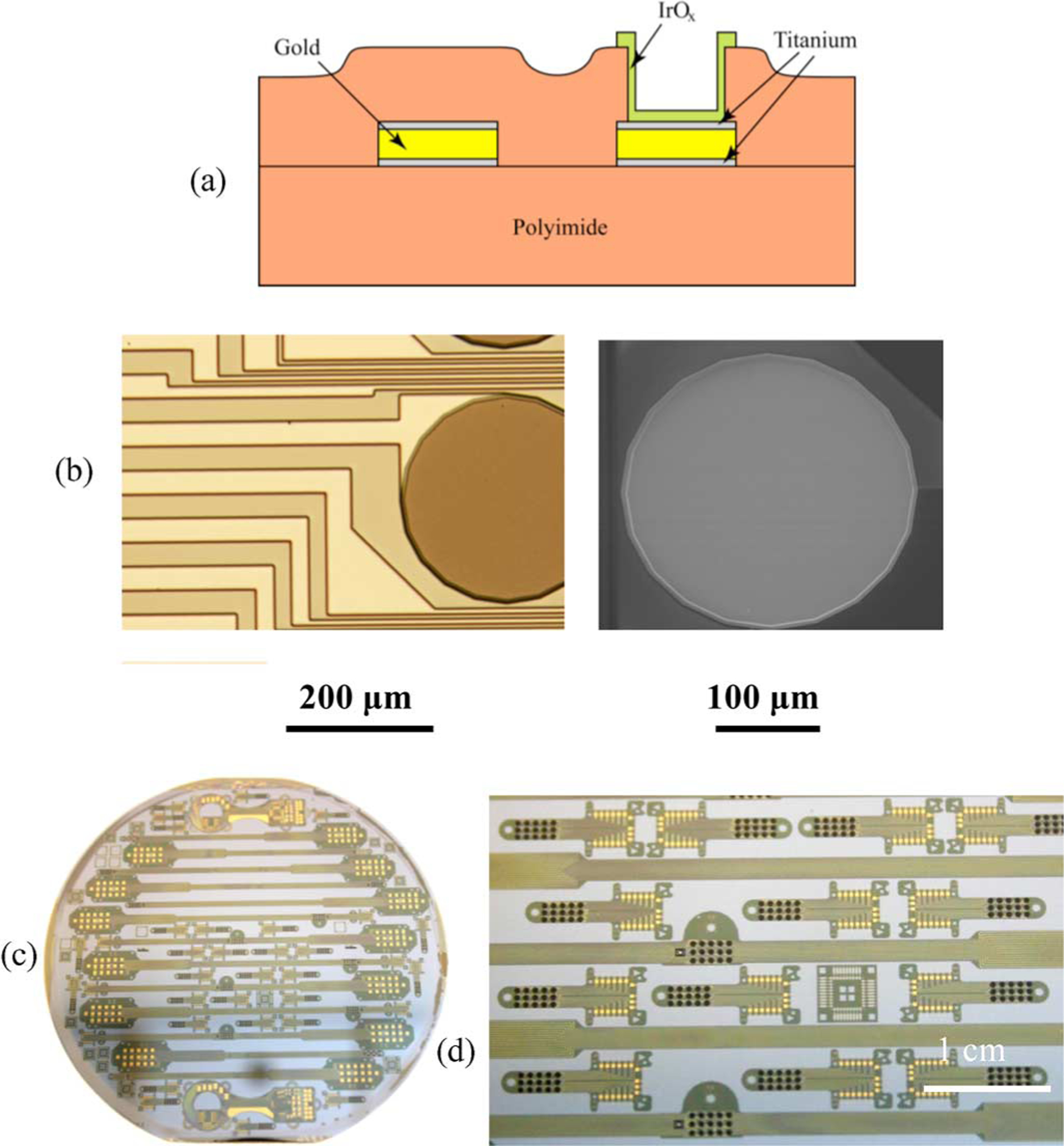
(a) Schematic cross section diagram showing the electrode array fabrication process. (b) Light micrograph of an IrOx stimulating site immediately postfabrication, and at right, an SEM of an identical 400-μm-diameter site after one year of continuous, biphasic current pulsing (0.76 mC/cm2, 0.95 μC/phase). (c) A 100-mm-diameter Si host wafer with IrOx electrode arrays for both acute and chronic stimulation studies. (d) Close-up micrograph showing numerous arrays, each having 15 IrOx electrode sites (small dark circles).
C. Electrode Array Testing
Long-term pulsing studies were performed on 400-μm-diameter electrodes at a charge-injection density of 0.76 mC/cm2 for 16 pulses/s. In the interpulse period, our stimulator used a weak current source to pull the electrode potential back up to +0.6 V with respect to the gold counter electrode, which was determined to be the optimal biasing condition for the iridium oxide stimulating sites. In the interphase (or intra-pulse) period, the electrode potential was allowed to float, but only briefly (on the order of microseconds). An asymmetric current waveform was employed with a 1 ms leading cathodal phase followed by a 4 ms anodal phase with a fourth of the cathodal current. Pulsing of a total of 84 electrodes was conducted in model interstitial fluid (ISF) at 37 °C for an average of 177 days, and a maximum of 409 days. ISF was used as it was believed to be the closest analog to the inorganic environment of the subretinal space. A representative comparison of the cyclic voltammogram (CV) of a site on one array is shown in Fig. 6 at the initiation and at the 228-day time point of the pulsing study. The observed increase in charge storage capacity (determined from the time-integral of the cathodal current in one CV cycle) occurred early in the experiment, and is related to rehydration and possibly some structural modification of the SIROF during pulsing. Of the 84 total electrode sites, 59 were functioning normally when testing was ended. In this one example, the metallization of ten electrodes became discontinuous due to gold dissolution at sites where the polyimide did not completely cover the metal traces, and 15 sites were judged to have failed because of separation of the gold metallization from the underlying polyimide at the charge-injection site. In only one electrode was there evidence of SIROF delamination from the underlying gold due to pulsing, and this was limited to a small area along the perimeter of the electrode adjacent to the polyimide. In general, those sites exhibiting partial or full gold delamination from the polyimide exhibited normal driving voltage and CV responses until the charge-injection coating (Au and SIROF) separated from the array. Our team judged from these data that electrode arrays constructed in the manner described would be quite adequate for months-long animal implantation trials, but that further work was necessary to improve the long-term integrity of these flexible, polyimide-based structures to create clinically appropriate devices. We now have encouraging preliminary results indicating that the lifetime of arrays made with an improved process can be extended to more than ten years, using accelerated tests performed at 87 °C.
Fig. 6.
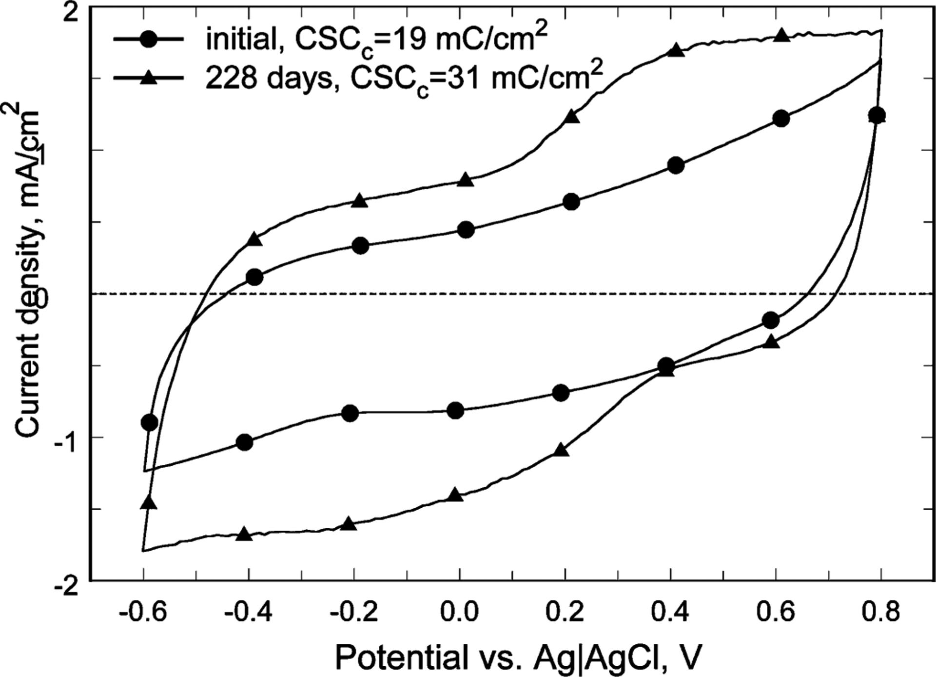
Comparison of the CVs of a representative SIROF stimulating electrode, initially and after 228 days pulsing (0.76 mC/cm2, 0.95 μC/phase) at 16 pulses/s. The increase in charge storage capacity is attributed to rehydration and structural modification of the SIROF during pulsing.
D. Ab Externo Implantation Procedure
Microstimulators were implanted in three Yucatan minipigs weighing ~20 kg by the following procedure, which is depicted in Fig. 7. Animal protocols were approved by local animal care and use committees, and conformed to the National Institutes of Health guidelines.
Fig. 7.
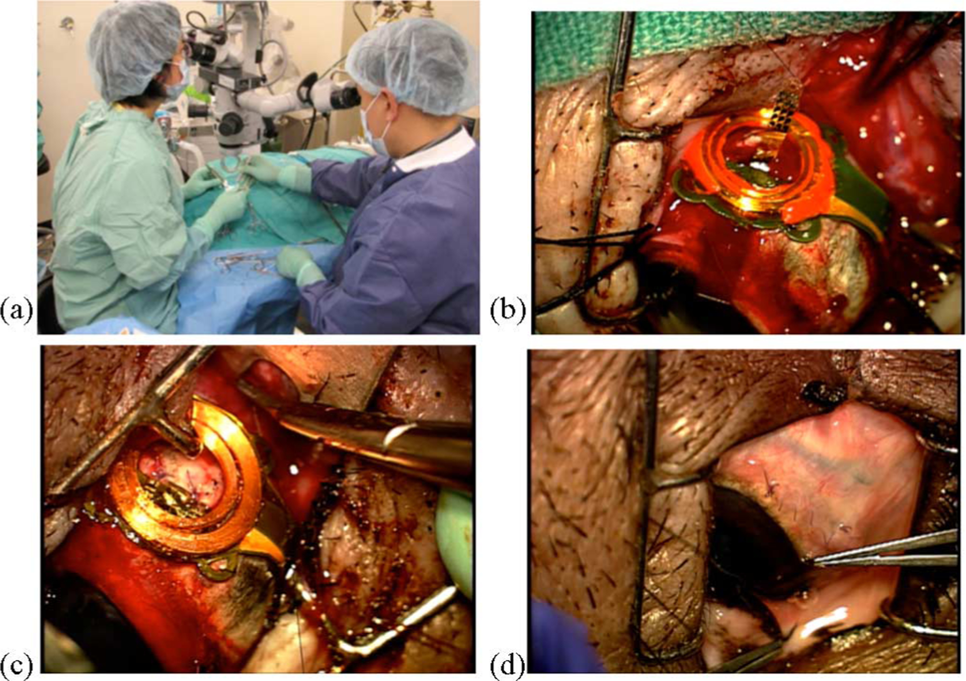
(a) Implantation of a microstimulator. (b) Prosthesis is sutured over the location of the sclera flap. In this surgery, a polyimide guide was used to prepare the way for the electrode array (seen here prior to insertion). (c) Array has been inserted, the guide removed, and the sclera flap sutured back in place. (d) Conjunctiva has been sutured back over the implant.
A preoperative electroretinogram (ERG) measurement was made to verify the overall health of the pig retina using a computer-controlled flash lamp and a contact lens electrode. Next, after making a lateral canthotomy and cutting open the conjunctiva, traction sutures were placed around the rectus muscles, and a partial thickness scleral flap (3 × 2.5 mm) was dissected 10 mm posterior to the limbus in the superior temporal quadrant. By applying pressure to the outside of the eye at this site while observing the retina, the intended site of implantation of the electrode array was visualized. A partial vitrectomy (to remove some of the “core” region of the vitreous body and enable the raising of a retinal bleb) was then performed near this location. The tip of a 30-gauge cannula was inserted through the retina, and a small amount of buffered saline solution and then Healon was injected to create the bleb, thus elevating and protecting the retina from harm. The superior rectus muscle was then cut at its anterior end, and the microstimulator (shown in Fig. 2) was sutured in place with the center of the device fixed underneath the former muscle location and the coils positioned over the scleral flap. Moderate systemic hypotension (achieved using a sodium nitroprusside drip) was used to reduce the potential for bleeding as the array was inserted through the highly vascular choroid that lies beneath the retina. In the first implantation, a polyimide guide (2 mm × 15 mm × 75 μm) was inserted through the scleral flap into the subretinal space under the bleb. This guide was used as a substrate upon which to extend a 6–8 mm length of the array. In subsequent implantations, we found it more expedient to bond a 16-μm-thick stiffener to the choroidal side of the electrode array with a silicone adhesive prior to surgery. This eliminated the need for a separate guide, since the stiffened array could now be inserted without one. Once the array was in place, the scleral flap was closed, and the final location of the electrodes was visually confirmed. The superior rectus muscle was sutured back, and the sclerotomies and the conjunctiva were closed. Fig. 8 shows a fundus photograph of an array in the subretinal space and a histological slide indicating good biocompatibility of the polyimide material after weeks of implantation.
Fig. 8.

(a) Fundus photograph of an electrode array in the subretinal space taken one week postsurgery. Note retinal blood vessels over the implant site. (b) Histological slide showing minimal adverse tissue responses to the presence of a polyimide strip (center of photograph) in the subretinal space of a Yucatan minipig. There is only slight gliosis and limited proliferation of dark colored retinal pigment epithelial (RPE) cells near the array (after [16]).
III. Results
A. In Vitro Functional Testing
In vitro evaluation consisted of dry and “wet” functional testing in buffered saline solution to simulate the overall orbital environment. In both cases, the prosthesis was placed in close proximity to a primary coil assembly while data waveforms to drive the device were generated by a portable peripheral component interconnect extensions for instrumentation (PXI) computer system with a LabVIEW graphical user interface that allowed selection of current levels, pulse timing, bias values, data carrier frequency, and data rate (see Table III for typical parameters). Manually generated stimulation patterns were used rather than employing the video input that would be used in a clinical device; an electronic vision system is under development, and will be reported elsewhere. Prior to encapsulating the completed implants for surgery, a “test tail” extension to the electrode array was used to measure output waveforms at the electrodes while the device was wirelessly driven. Fig. 9 shows a typical electrode waveform measured in this manner. The circuit configuration of the dummy load used for our in vitro trials to simulate the in vivo site impedance consisted of a series resistor of 4 kΩ (representing the access resistance and the series resistance of the lead), and a parallel combination of a 20 kΩ resistor and a 0.047 μF capacitor representing the electrode–tissue interface. The effect of the access resistance can be seen in Fig. 9 as the small, sharp voltage drop at the onset of the pulse. The effect of the capacitor, whose voltage would be linear with time when driven by a constant current, can be seen as the sloped trace following the vertical drop. If there is a charge imbalance between the two pulses, the charge on the capacitor will slowly dissipate through the parallel resistor.
TABLE III.
Typical Parameters Transmitted Wirelessly to the Microstimulator
| Stimulation Pattern | Biphasic, cathodal pulse first |
|---|---|
| Pulse duration | 1 ms cathodal pulse immediately followed by a 1 ms anodal pulse |
| Pulse amplitude | 25 μA each phase on any of 15 electrodes, programmable up to 775 μA in 25 μA steps |
| Repetition Interval | ~2Hz |
Fig. 9.
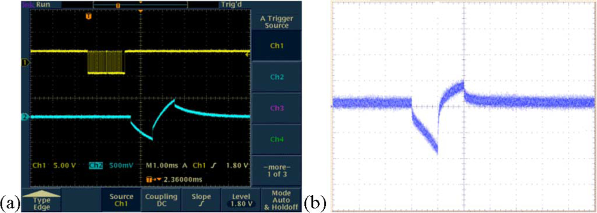
Typical electrode voltage waveforms (a) when the stimulator drove a dummy load consisting of a series resistor of 4 kΩ (representing the access resistance and the series resistance of the lead), and a parallel combination of a 20 kΩ resistor and a 0.047 μF capacitor representing the electrode–tissue interface (the top trace shows the binary bitstream used to command the device and the bottom trace shows the voltage output.) (b) Representative electrode voltage waveform when the stimulator was wirelessly powered in saline solution, measured using a “test tail” extension of the IrOx electrode array that reached back out of the bath. The noise is due to RF interference from the transmitter.
After testing the implants in a “dry” environment, we immersed the devices in buffered saline solution. In order to simulate the in vivo test conditions, where we would no longer have direct access to the electrode voltage waveforms, we measured the potential generated by the stimulating sites by placing two needle electrodes (as well as a third, reference electrode) into the saline solution and measuring the voltage difference between the two. This was proportional to the current sourced or sunk by the stimulating electrodes. The absolute magnitude of this voltage difference was highly dependent upon the placement of the two sensing electrodes. If they were placed on equipotential lines, no voltage difference was measured at all. At the other extreme, one needle electrode could be placed in close proximity to the electrode array, and the other could be in close proximity to the return electrode on the flexible substrate. In order to best model the in vivo experiments, neither of these two extremes was used for in vitro testing. Although the microstimulator used did not have “reverse” telemetry capabilities with which to monitor the actual instantaneous electrode waveforms, we assumed that the total in vivo potential at the stimulating and return electrodes was less than the maximal power supply voltage swing because: 1) our team had previously built prostheses that incorporated a “test tail” on the electrode array that allowed continuous in vitro monitoring of the actual electrode waveforms and 2) the charge density at which the electrodes were driven (20 μC/cm2) was two orders of magnitude below the maximal charge density for the iridium oxide films used, and the resulting voltage at the electrode–tissue interface was thus well within the water “window.” The stimulus artifacts measured by the needle electrode technique were only a few millivolts in amplitude, and the actual electrode voltages were clearly larger; the potential measurements were used only to obtain a relative indication of stimulator functioning. Fig. 10 shows the test setup and a sample waveform collected in the manner described; note the difference between this signal (which is proportional to current) and the electrode voltage waveform of Fig. 9 (which reflected the effects of the access resistance and the electrode–tissue impedance). The nonzero final voltage of Fig. 10 does not represent a charge imbalance; rather, it represents an offset in the differential amplifier used to make the stimulus artifact measurement. Additionally, there is a very small positive interpulse current that is used by the stimulator chip to maintain the electrode potential.
Fig. 10.
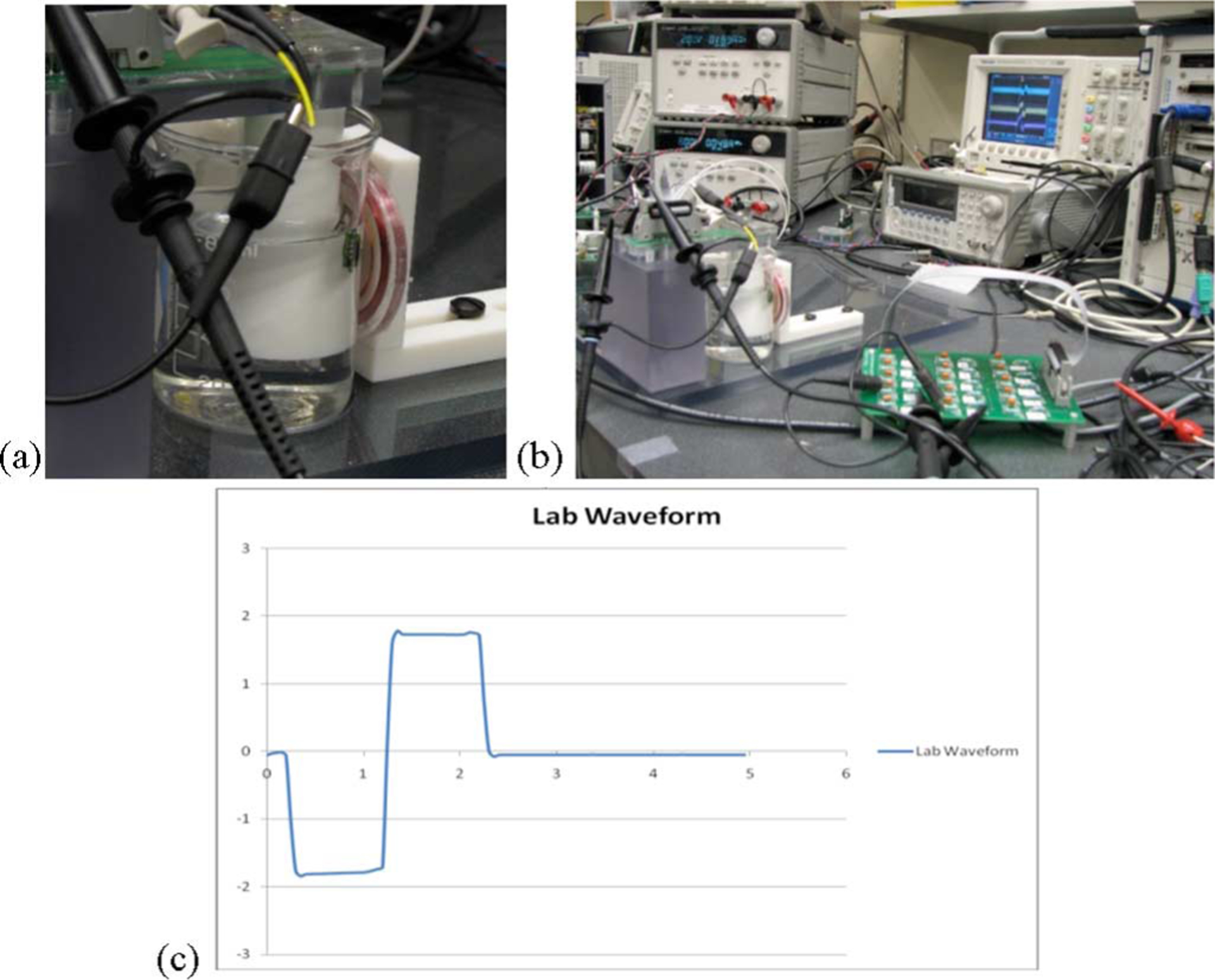
(a) Testing the wireless microstimulator in a saline bath. (b) In vitro test setup. (c) Measured potential difference (in millivolts) between two needle electrodes placed in close proximity to the prosthesis in a saline bath, while biphasic test current pulses of 25 μA were stimulated. Time scale: 1 ms/division.
After up to 30 weeks of implantation, devices were explanted, retested in vitro, and found to work as well as they did preoperatively. The electrode impedance did not change significantly during the implantation period, as the IrOx sites were hydrated during initial testing prior to assembly.
B. In Vivo Testing
For animal surgical trials, the wireless driver/transmitter described before was mounted on a cart. In Fig. 11(a), representative ERG traces show no significant changes between preoperative and postoperative measurements. Fig. 11(b) shows our PXI computer system along with the associated power supplies and transmitter components. In Fig. 11(c), two members of our team are testing an implanted stimulator. The primary coil assembly of Fig. 3(b), attached at one end to the power and data transmitters, was placed over the eye of the animal [see Fig. 11(d) and (e)], while artifact waveforms in response to wirelessly generated stimuli were recorded using a contact lens electrode and displayed on the monitor. There was no measurable difference in the current-source outputs to each electrode with minor variations in coil position or after months of implantation, provided that sufficient power was transmitted to activate the implant.
Fig. 11.
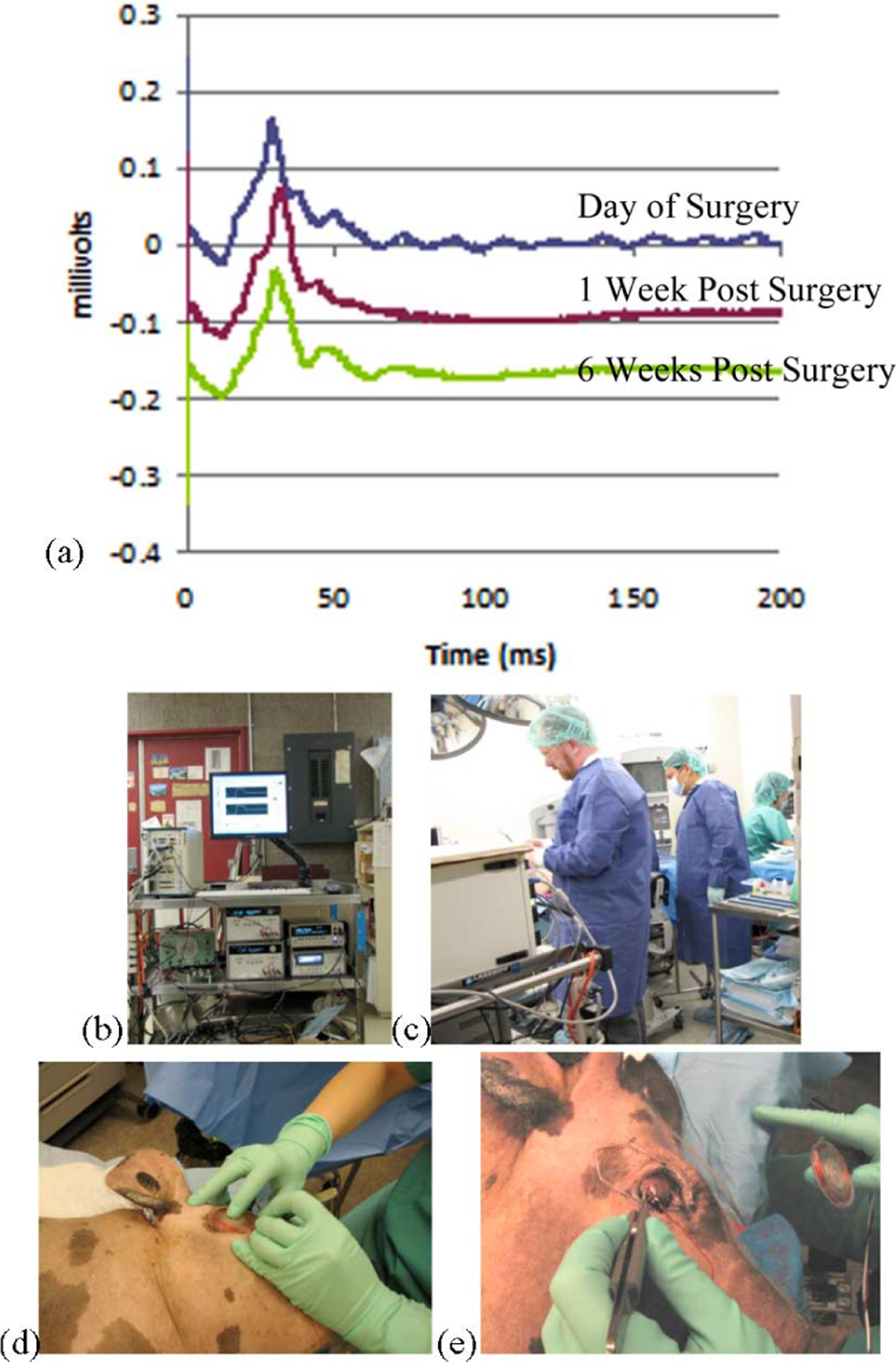
In vivo testing. (a) Representative ERG traces showing no significant changes in waveform between preoperative and postoperative measurements. (b) Photograph showing the wireless transmission system and PXI computer driver in operation. The cart also contains dc power supplies and the power and data transmitters. (c) System in operation during surgery. (d) and (e) Contact lens electrode is applied to the eye to measure stimulus artifacts, and the primary coils are positioned to drive the prosthesis.
Representative stimulus artifact waveforms recorded in this manner are shown in Fig. 12. The “control” signal was collected by reducing the transmitted power to the implant sufficiently to prevent the stimulator from starting operation; clearly, there was no stimulus artifact in this case. The magnitude of the artifacts measured was strongly affected by the positioning of the contact lens electrode used to sense them; thus, Fig. 12 should be interpreted primarily as an indication of ongoing microstimulator functioning, rather than any physiological phenomenon. Our team attempted surface cortical recordings in minipig brain to assess visually and electrically evoked responses to stimulation. Surgical access to this region proved difficult, however, due to the pig anatomy, and no cortical recordings were made.
Fig. 12.
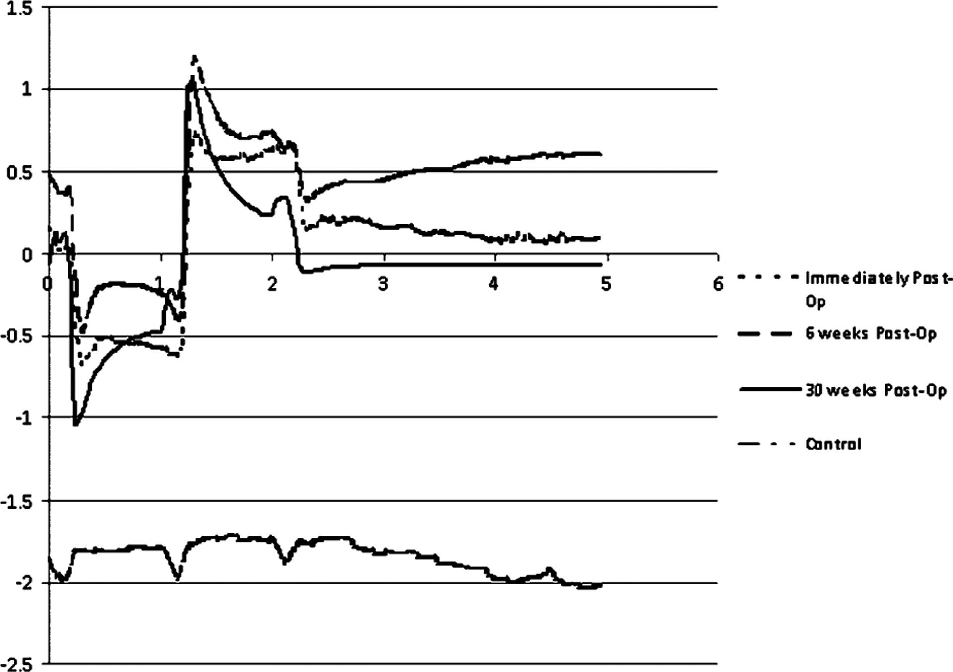
Representative waveforms of stimulus artifacts from wirelessly driven retinal microstimulators in Yucatan minipigs at 0, 2, 6, and 12 weeks postoperation. The “control” waveform was collected when transmitted power to the implant was reduced below the threshold that was required for stimulation to begin. The potential scale (in millivolts) is only relative, as the readings were highly sensitive to changes in the position of the contact lens electrode. Time scale: 1 ms/division.
Because of the bulk of the implant, exposure of parts of the prosthesis through the conjunctiva was observed in some cases. Fig. 13 shows photographs of minipig eyes that demonstrate this phenomenon. We believe that moving the device circuitry to the posterior of the eye orbit would help to alleviate this problem, and indeed, preliminary results with new prosthesis designs indicate that this is the case. A more optimal microstimulator configuration would thus leave only a thin secondary coil underneath the conjunctiva in the anterior orbit.
Fig. 13.
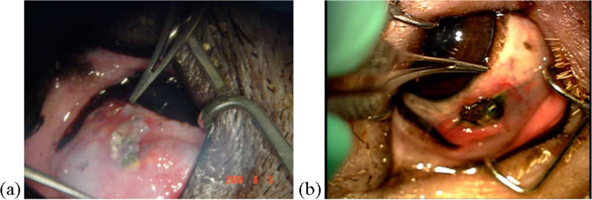
Photographs demonstrating partial exposure of different implanted microstimulators through the minipig conjunctiva. (a) 3 weeks after surgery. (b) 18 weeks after surgery.
IV. Discussion and Conclusion
A complete, wirelessly driven subretinal neurostimulator has been developed for months-long experimental trials in Yucatan minipig models, along with a computer-based driver and RF transmitters. Operation of the retinal prosthesis in animals has been verified for over seven months. Long-term testing clearly indicated that degradation or delamination of implant components would limit the useful lifetime of our current device design to approximately 9–18 months in vivo. This limitation thus precludes the implantation of visual prostheses having similar construction methods for years-long clinical trials. Accordingly, our team has focused on hermetic packaging technology and lifetime extension for microelectrode arrays to develop clinically relevant prosthetics.
Although the primary goal of this effort was to demonstrate the feasibility of our ab externo surgical approach to visual prosthesis implantation, we were also able to wirelessly deliver stimulation currents with the system reported here that were well in excess of perceptual threshold currents measured previously in both human and animal models. A solid foundation was thus laid for future implementation of hermetically packaged subretinal neurostimulators for the restoration of useful vision to blind patients.
Acknowledgment
The authors wish to recognize the contributions of former team members, M. Kenney, S.-J. Kim, J. Loewenstein, S. Montezuma, H. Shah, L. Snebold, G. Swider, and B. Yomtov, as well as the administrative assistance of K. Quinn and P. Davis and the technical assistance of J. Dumser, D. Ghera, A. Hayward, T. Plante, C. Wong, and S. Behan. The authors also acknowledge C. Piña and MOSIS for in-kind foundry services in support of their research.
This work was supported in part by the Veterans Affairs Center for Innovative Visual Rehabilitation, in part by the National Science Foundation (NSF) (IIS-0515134), in part by the National Institutes of Health (EY016674-01), in part by the NSF’s support to the Cornell NanoScale Science and Technology Facility (part of the NationalNanofabrication Infrastructure Network), and in part by private donors
Biographies

Douglas B. Shire (S’84–M’08) received the B.S. degree from Rensselaer Polytechnic Institute, Troy, NY, in 1984, and the Ph.D. degree in electrical engineering from Cornell University, Ithaca, NY, in 1989.
From 1989 to 1994, he was with the Optoelectronics Division, Hewlett-Packard, San Jose, CA. Between 1994 and 1997, he joined Cornell University as a Postdoctoral Associate, where he is currently a Visiting Scientist. He was an Adjunct Assistant Professor in the Electrical Engineering Department, Syracuse University, New York. In 1997, he joined the Boston Retinal Implant Project (BRIP) team, where he developed microfabrication processes for creating electrode arrays for neurostimulation as a member of the Veterans Affairs Center for Innovative Visual Rehabilitation (VA CIVR), VA Boston Healthcare System, Boston, MA. Since 2006, he has been the Engineering Manager for the VA CIVR retinal prosthesis development team.
Dr. Shire is a member of Tau Beta Pi, Eta Kappa Nu, and the Association for Research in Vision and Ophthalmology.

Shawn K. Kelly (M’03) received the S.B. degree in electrical engineering with minors in biomedical engineering and in biology, the M.Eng. degree in electrical engineering, and the Ph.D. degree in electrical engineering from the Massachusetts Institute of Technology (MIT), Cambridge, in 1996, 1998, and 2003, respectively.
He has worked in undergraduate research positions studying cartilage and brain tissue resistivity at MIT and at the University of Pittsburgh Medical Center. He was also a Summer Test Engineer at M/A-Com, Inc. Since 2003, he has been with the Boston Retinal Implant Project (BRIP), as a Research Engineer with the Veterans Affairs Boston Healthcare System, Boston, MA, and also as a Visiting Scientist at MIT. His current research interests include integrated circuit design, power and data telemetry, and power management.
Dr. Kelly is a member of Sigma Xi and the Association for Research in Vision and Ophthalmology.

Jinghua Chen received the M.D. degree from Peking University Health Science Center, Beijing, China, in 1995, and the Ph.D. degree from Peking University, Beijing, in 1999.
She completed her internship at the 3rd Clinical Hospital of Peking University, followed by an ophthalmology residency at the 2nd Clinical Hospital, Peking University, where she also became a faculty member in 1999. In 2004, she joined the Boston Retinal Implant Project. She is currently with the Massachusetts Eye and Ear Infirmary, Boston, MA. She is engaged in acute and chronic in vivo research to test the biocompatibility of the implant and has developed improved surgical methods for subretinal electrode array and prosthesis module implantation.
Dr. Chen is a member of the Association for Research in Vision and Ophthalmology.

Patrick Doyle received the S.B. degree in electrical engineering from the Massachusetts Institute of Technology, Cambridge, in 1987, and the M.S. degree in electrical engineering from Northeastern University, Boston, MA, in 1995.
He has worked in industry for more than 20 years, and has developed digital communications systems for applications including intercept systems, underwater acoustic communications, cell phones, and law enforcement communications systems. Since 2007, he has been a Research Engineer with the Boston Retinal Implant Project, Boston Veterans Affairs Research Institute, Boston, MA. He is also with the Massachusetts Eye and Ear Infirmary, Boston.
Mr. Doyle is a member of the Association for Research in Vision and Ophthalmology.

Marcus D. Gingerich received the B.S. degree in electrical engineering from Michigan Technological University, Houghton, in 1992, and the M.S. degree in biomedical engineering, and the M.S. and Ph.D. degrees in electrical engineering from the University of Michigan, Ann Arbor, in 1994, 1996, and 2002, respectively.
In 2002, he joined the Boston Retinal Implant Project, Veterans Affairs Center for Innovative Visual Rehabilitation, Boston, MA, as a Biomedical Research Engineer. He is also a Visiting Scientist at Cornell University, Ithaca, NY. He is currently engaged in researching advanced microfabrication technologies related to the development of a retinal prosthesis.
Dr. Gingerich is a member of the Association for Research in Vision and Ophthalmology.

Stuart F. Cogan (M’95) received the B.Sc. degree in mechanical engineering and the M.S. degree in materials science from Duke University, Durham, NC, in 1975 and 1977, respectively, and the Sc.D. degree in materials science from the Massachusetts Institute of Technology, Cambridge, in 1979.
He is currently the Director of Advanced Materials Research at EIC Laboratories, Inc., Norwood, MA. His research interests include materials for encapsulating implanted medical devices, and electrode materials for stimulation and recording.

William A. Drohan (M’07) received the B.E.E. degree from Manhattan College, New York, in 1958, and the M.E.E. degree from Rensselaer Polytechnic Institute, Troy, NY, in 1960.
Since 2005, he has been a Research Engineer with the Veterans Affairs (VA) Center for Innovative Visual Rehabilitation, VA Boston Healthcare System, Boston, MA, and also a Massachusetts Institute of Technology Affiliate. His current research interests include modeling of neural systems. He holds numerous patents.
Mr. Drohan is a member of Eta Kappa Nu and Sigma Xi.

Oscar Mendoza received the Associate’s degree in electrical engineering with a minor in electronics from the Central-America Institute of Technology, La Union, El Salvador, and a second Associate’s degree in engineering technology from Wentworth Institute of Technology, Boston, MA.
Since 2007, he has been with the Boston Retinal Implant Project, as a Senior Electro-Mechanical Technician at Massachusetts Institute of Technology, Cambridge.

Luke Theogarajan received the Ph.D. degree from Massachusetts Institute of Technology (MIT), Cambridge, in 2007.
He is currently an Assistant Professor of electrical and computer engineering at the University of California, Santa Barbara. His research interests include combining the processing power of electronics with the versatility of synthetic chemistry to develop neural prosthetic devices. He holds four patents.

John L. Wyatt (S’75–M’78–SM’95) received the B.S. degree from Massachusetts Institute of Technology (MIT), Cambridge, in 1968, the M.S. from Princeton University, Princeton, NJ, in 1970, and the Ph.D. degree from the University of California, Berkeley, in 1979, all in electrical engineering.
After a year of postdoctoral research in the Department of Physiology, Medical College, Richmond, Virginia, he joined the Department of Electrical Engineering and Computer Science at MIT, where he is now a Professor; he headed a project on analog integrated circuits for machine vision from 1988 to 1995. He is also the Co-Director of the Boston Retinal Implant Project.

Joseph F. Rizzo received the B.S. degree from Louisiana State University, Baton Rouge, in 1974, and the M.D. degree from Louisiana State University Medical School, New Orleans, in 1978.
He completed an internship in adult medicine at Los Angeles Medical Center, University of California, followed by a neurology residency at Tufts University–New England Medical Center, and then an ophthalmology residency at Boston University. He performed a clinical fellowship in neuroophthalmology at the Department of Ophthalmology, Massachusetts Eye and Ear Infirmary/Harvard Medical School, Boston, where he later joined the academic faculty. He initiated the Retinal Implant Project in 1988, and since then, has been involved in the evaluation of patients with neuroophthalmologic disease and the codirection and research endeavors of the Boston Retinal Implant Project. He is also the Director of the Center for Innovative Visual Rehabilitation, Veterans Affairs Medical Center, Boston, MA.
Prof. Rizzo received the “Dean’s Award” from Louisiana State University Medical School in recognition of outstanding leadership and performance, and a Physician Training Award from the National Institutes of Health.
Contributor Information
Douglas B. Shire, Veterans Affairs (VA) Center for Innovative Visual Rehabilitation, VA Boston Healthcare System, Boston, MA 02130 USA,; Cornell University, Ithaca, NY 14853 USA
Shawn K. Kelly, Veterans Affairs (VA) Center for Innovative Visual Rehabilitation, VA Boston Healthcare System, Boston, MA 02130 USA.
Jinghua Chen, Massachusetts Eye and Ear Infirmary, Boston, MA 02114 USA.
Patrick Doyle, Boston Veterans Affairs Research Institute, Boston, MA 02130 USA,; Massachusetts Eye and Ear Infirmary, Boston, MA 02114 USA
Marcus D. Gingerich, Veterans Affairs Center for Innovative Visual Rehabilitation, Boston, MA 02130 USA, Cornell University, Ithaca, NY 14853 USA
Stuart F. Cogan, EIC Laboratories, Inc., Norwood, MA 02062 USA.
William A. Drohan, Veterans Affairs (VA) Center for Innovative Visual Rehabilitation, VA Boston Healthcare System, Boston, MA 02130 USA.
Oscar Mendoza, Massachusetts Institute of Technology, Cambridge, MA 02139 USA.
Luke Theogarajan, Massachusetts Institute of Technology, Cambridge, MA 02139 USA.; University of California, Santa Barbara, CA 93106 USA
John L. Wyatt, Massachusetts Institute of Technology, Cambridge, MA 02139 USA.
Joseph F. Rizzo, Massachusetts Eye and Ear Infirmary/Harvard Medical School, Boston, MA 02114 USA, Center for Innovative Visual Rehabilitation, Veterans Affairs Medical Center, Boston, MA 02130 USA
References
- [1].de Balthasar C, Patel S, Roy A, Freda R, Greenwald S, Horsager A, Mahadevappa M, Yanai D, McMahon MJ, Humayun MS, Greenberg RJ, Weiland JD, and Fine I, “Factors affecting perceptual thresholds in epiretinal prostheses,” Invest. Ophthalmol. Vis. Sci, vol. 49, pp. 2303–2314, 2008. [DOI] [PMC free article] [PubMed] [Google Scholar]
- [2].Zhou JA, Woo SJ, Park SI, Kim ET, Seo JM, Chung H, and Kim SJ, “A suprachoroidal electrical retinal stimulator design for long-term animal experiments and in-vivo assessment of its feasibility and biocompatibility in rabbits,” J. Biomed. Biotech, vol. 2008, pp. 547428-1–547428-10, 2008. [DOI] [PMC free article] [PubMed] [Google Scholar]
- [3].Schanze T, Hesse L, Lau C, Greve N, Haberer W, Kammer S, Doerge T, Rentzos A, and Stieglitz T, “An optically powered single-channel stimulation implant as test system for chronic biocompatibility and biostability of miniaturized retinal vision prostheses,” IEEE Trans. Biomed. Eng, vol. 54, no. 6, pp. 983–992, June 2007. [DOI] [PubMed] [Google Scholar]
- [4].Yanai D, Weiland JD, Mahadevappa M, Greenberg RJ, Fine I, and Humayun MS, “Visual performance using a retinal prosthesis in three subjects with retinitis pigmentosa,” Amer. J. Ophthalmol, vol. 143, pp. 820–827, 2007. [DOI] [PubMed] [Google Scholar]
- [5].Wong YT, Dommel N, Preston P, Hallum LE, Lehmann T, Lovell NH, and Suaning GJ, “Retinal neurostimulator for a multifocal vision prosthesis,” IEEE Trans. Neural Syst. Rehabil. Eng, vol. 15, no. 3, pp. 425–434, September 2007. [DOI] [PubMed] [Google Scholar]
- [6].Hornig R, Zehnder T, Velikay-Parel M, Laube T, Feucht M, and Richard G, “The IMI retinal implant system,” in Artificial Sight: Basic Research, Biomedical Engineering, and Clinical Advances, Humayun MS, Weiland JD, Chader G, and Greenbaum E, Eds. New York: Springer-Verlag, 2007, pp. 111–128. [Google Scholar]
- [7].DeMarco PJ Jr., Yarbrough GL, Yee CW, Mclean GY, Sagdullaev BT, Ball SL, and McCall MA, “Stimulation via a subretinally placed prosthetic elicits central activity and induces a trophic effect on visual responses,” Invest. Ophthalmol. Vis. Sci, vol. 48, pp. 916–926, 2007. [DOI] [PubMed] [Google Scholar]
- [8].Zrenner E, “Restoring neuroretinal function: New potentials,” Doc. Ophthalmol, vol. 115, pp. 56–59, 2007. [Google Scholar]
- [9].Gerding H, “A new approach towards a minimal invasive retina implant,” J. Neural Eng, vol. 4, pp. S30–S37, 2007. [DOI] [PubMed] [Google Scholar]
- [10].Gerding H, Benner FP, and Taneri S, “Experimental implantation of epiretinal retina implants (EPI-RET) with an IOL-type receiver unit,” J. Neural Eng, vol. 4, pp. S38–S49, 2007. [DOI] [PubMed] [Google Scholar]
- [11].Winter JO, Cogan SF, Rizzo JF III, “Retinal prostheses: Current challenges and future outlook,” J. Biomater. Sci. Polym. Ed, vol. 18, pp. 1031–1055, 2007. [DOI] [PubMed] [Google Scholar]
- [12].Terasawa Y, Tashiro H, Uehara A, Saitoh T, Ozawa M, Tokuda T, and Ohta J, “The development of a multichannel electrode array for retinal prostheses,” J. Artif. Organs, vol. 9, pp. 263–266, 2006. [DOI] [PubMed] [Google Scholar]
- [13].Shah HA, Montezuma SR, and Rizzo JF, “In vivo electrical stimulation of rabbit retina: Effect of stimulus duration and electrical field orientation,” Exp. Eye Res, vol. 83, pp. 247–254, 2006. [DOI] [PubMed] [Google Scholar]
- [14].Eckhorn R, Wilms M, Schanze T, Eger M, Hesse L, Eysel UT, Kisvárday ZF, Zrenner E, Gekeler F, Schwahn H, Shinoda K, Sachs H, and Walter P, “Visual resolution with retinal implants estimated from recordings in cat visual cortex,” Vis. Res, vol. 46, pp. 2675–2690, 2006. [DOI] [PubMed] [Google Scholar]
- [15].Schanze T, Sachs HG, Wiesenack C, Brunner U, and Sailer H, “Implantation and testing of subretinal film electrodes in domestic pigs,” Exp. Eye Res, vol. 82, pp. 332–340, 2006. [DOI] [PubMed] [Google Scholar]
- [16].Montezuma SR, Loewenstein J, Scholz C, and Rizzo JF III, “Bio-compatibility of materials implanted into the subretinal space of yucatan pigs,” Invest. Ophthalmol. Vis. Sci, vol. 47, pp. 3514–3522, 2006. [DOI] [PubMed] [Google Scholar]
- [17].Besch D, Sachs H, Szurman P, Gülicher D, Wilke R, Reinert S, Zrenner E, Bartz-Schmidt KU, and Gekeler F, “Extraocular surgery for implantation of an active subretinal visual prosthesis with external connections: Feasibility and outcome in seven patients,” Br. J. Ophthalmol, vol. 92, no. 10, pp. 1361–1368, November 2008. [DOI] [PubMed] [Google Scholar]
- [18].Yamauchi Y, Franco LM, Jackson DJ, Naber JF, Ziv RO, Rizzo JF, Kaplan HJ, and Enzmann V, “Comparison of electrically evoked cortical potential thresholds generated with subretinal or suprachoroidal placement of a microelectrode array in the rabbit,” J. Neural Eng, vol. 2, pp. S48–S56, 2005. [DOI] [PubMed] [Google Scholar]
- [19].Sachs HG, Gekeler F, Schwahn H, Jakob W, Kohler M, Schulmeyer F, Marienhagen J, Brunner U, and Framme C, “Implantation of stimulation electrodes in the subretinal space to demonstrate cortical responses in yucatan minipig in the course of visual prosthesis development,” Eur. J. Ophthalmol, vol. 15, pp. 493–499, 2005. [PubMed] [Google Scholar]
- [20].Sachs HG, Schanze T, Brunner U, Sailer H, and Wiesenack C, “Transscleral implantation and neurophysiological testing of subretinal polyimide film electrodes in the domestic pig in visual prosthesis development,” J. Neural Eng, vol. 2, pp. S57–S64, 2005. [DOI] [PubMed] [Google Scholar]
- [21].Pardue MT, Phillips MJ, Yin H, Sippy BD, Webb-Wood S, Chow AY, and Ball SL, “Neuroprotective effect of subretinal implants in the RCS rat,” Invest. Ophthalmol. Vis. Sci, vol. 46, pp. 674–682, 2005. [DOI] [PubMed] [Google Scholar]
- [22].Nakauchi K, Fujikado T, Kanda H, Morimoto T, Choi JS, Ikuno Y, Sakaguchi S, Kamei M, Ohji M, Yagi T, Nishimura S, Sawai H, Fukuda Y, and Tano Y, “Transretinal electrical stimulation by an intrascleral multichannel electrode array in rabbit eyes,” Graefe’s Arch. Clin. Exp. Ophthalmol, vol. 243, pp. 169–174, 2005. [DOI] [PubMed] [Google Scholar]
- [23].Hornig R, Laube T, Walter P, Velikay-Parel M, Bornfield N, Feucht M, Akguel H, Rössler G, Alteheld N, Lütke-Notarp D, Wyatt J, and Richard G, “A method and technical equipment for an acute human trial to evaluate retinal implant technology,” J. Neural Eng, vol. 2, pp. S129–S134, 2005. [DOI] [PubMed] [Google Scholar]
- [24].Palanker D, Vankov A, Huie P, and Baccus S, “Design of a high resolution optoelectronic retinal prosthesis,” J. Neural Eng, vol. 2, pp. S105–S120, 2005. [DOI] [PubMed] [Google Scholar]
- [25].Güven D, Weiland JD, Fujii G, Mech BV, Mahadevappa M, Greenberg R, Roizenblatt R, Qju G, LaBree L, Wang X, Hinton D, and Humayun MS, “Long-term stimulation by active epiretinal implants in normal and RCD1 dogs,” J. Neural Eng, vol. 2, pp. S65–S73, 2005. [DOI] [PubMed] [Google Scholar]
- [26].Husain D and Loewenstein JI, “Surgical approaches to retinal prosthesis implantation,” Int. Ophthalmol. Clin, vol. 44, pp. 105–111, 2004. [DOI] [PubMed] [Google Scholar]
- [27].Palanker D, Huie P, Vankov A, Aramant R, Seiler M, Fishman H, Marmor H, and Blumenkranz M, “Migration of retinal cells through a perforated membrane: Implications for a high-resolution prosthesis,” Invest. Ophthalmol. Vis. Sci, vol. 45, pp. 3266–3270, 2004. [DOI] [PubMed] [Google Scholar]
- [28].Loewenstein JI, Montezuma SR, and Rizzo JF III, “Outer retinal degeneration: An electronic retinal prosthesis as a treatment strategy,” Arch. Ophthalmol, vol. 122, pp. 587–596, 2004. [DOI] [PubMed] [Google Scholar]
- [29].Kanda H, Morimoto T, Fujikado T, Tano Y, Fukuda Y, and Sawai H, “Electrophysiological studies of the feasibility of suprachoroidal–transretinal stimulation for artificial vision in normal and RCS rats,” Invest. Ophthalmol. Vis. Sci, vol. 45, pp. 560–566, 2004. [DOI] [PubMed] [Google Scholar]
- [30].Rizzo JF III, Wyatt J, Loewenstein J, Kelly S, and Shire D, “Perceptual efficacy of electrical stimulation of human retina with a microelectrode array during short-term surgical trials,” Invest. Ophthalmol. Vis. Sci, vol. 44, pp. 5362–5369, 2003. [DOI] [PubMed] [Google Scholar]
- [31].Rizzo JF III, Wyatt J, Loewenstein J, Kelly S, and Shire D, “Methods and perceptual thresholds for short-term electrical stimulation of human retina with microelectrode arrays,” Invest. Ophthalmol. Vis. Sci, vol. 44, pp. 5355–5361, 2003. [DOI] [PubMed] [Google Scholar]
- [32].Zrenner E, “Will retinal implants restore vision?” Science, vol. 295, pp. 1022–1025, 2002. [DOI] [PubMed] [Google Scholar]
- [33].Rizzo JF III, Wyatt J, Humayun M, de Juan E, Liu W, Chow A, Eckmiller R, Zrenner E, Yagi T, and Abrams G, “Retinal prosthesis: An encouraging first decade with major challenges ahead,” Ophthalmology, vol. 108, pp. 13–14, 2001. [DOI] [PubMed] [Google Scholar]
- [34].Stett A, Barth W, Weiss S, Haemmerle H, and Zrenner E, “Electrical multi-site stimulation of the isolated chicken retina,” Vis. Res, vol. 40, pp. 1785–1795, 2000. [DOI] [PubMed] [Google Scholar]
- [35].Marc RE, Jones BW, Anderson JR, Kinard K, Marshak DW, Wilson JH, Wensel TG, and Lucas RJ, “Neural reprogramming in retinal degenerations,” Invest. Ophthalmol. Vis. Sci, vol. 48, pp. 3364–3371, 2007. [DOI] [PMC free article] [PubMed] [Google Scholar]
- [36].Maguire AM, Simonelli F, Pierce EA, Pugh EN Jr., Mingozzi F, Bennicelli J, Banfi S, Marshall KA, Testa F, Surace EM, Rossi S, Lyubarsky A, Arruda VR, Konkle B, Stone E, Sun J, Jacobs J, Dell’Osso L, Hertle R, Ma J-X, Redmond TM, Zhu X, Hauck B, Zelenaia O, Shindler KS, Maguire MG, Wright JF, Volpe NJ, McDonnell JW, Auricchio A, High KA, and Bennett J, “Safety and efficacy of gene transfer for leber’s congenital amaurosis,” N. Engl. J. Med, vol. 358, pp. 2240–2248, 2008. [DOI] [PMC free article] [PubMed] [Google Scholar]
- [37].Congdon N, O’Colmain B, Klaver CC, Klein R, Munoz B, Friedman DS, Kempen J, Taylor HR, and Mitchell P, “Causes and prevalence of visual impairment among adults in the united states,” Arch. Ophthalmol, vol. 122, pp. 477–485, 2004. [DOI] [PubMed] [Google Scholar]
- [38].Friedman D, O’Colmain B, Muñoz B, Tomany SC, McCarty C, de Jong PT, Nemesure B, Mitchell P, and Kempen J, “Prevalence of age-related macular degeneration in the United States,” Arch. Ophthalmol, vol. 122, pp. 564–572, 2004. [DOI] [PubMed] [Google Scholar]
- [39].Jensen RJ and Rizzo JF III, “Responses of ganglion cells to repetitive electrical stimulation of the retina,” J. Neural Eng, vol. 4, pp. S1–S6, 2007. [DOI] [PubMed] [Google Scholar]
- [40].Fried S, Hsueh H, and Werblin F, “A method for generating precise temporal patterns of retinal spiking using prosthetic stimulation,” J. Neurophysiol, vol. 95, pp. 970–978, 2006. [DOI] [PubMed] [Google Scholar]
- [41].Brindley GS, “Sensations produced by electrical stimulation of the occipital poles of the cerebral hemispheres, and their use in constructing visual prostheses,” Ann. R. Coll. Surg. Engl, vol. 47, pp. 106–108, 1970. [PMC free article] [PubMed] [Google Scholar]
- [42].Brindley GS, “Effects of electrical stimulation of the visual cortex,” Hum. Neurobiol, vol. 1, pp. 281–283, 1982. [PubMed] [Google Scholar]
- [43].Dobelle WH and Mladejovsky MG, “Phosphenes produced by electrical stimulation of human occipital cortex, and their application to the development of a prosthesis for the blind,” J. Physiol, vol. 243, pp. 553–576, 1974. [DOI] [PMC free article] [PubMed] [Google Scholar]
- [44].Normann R, Maynard E, Rousche P, and Warren D, “A neural interface for a cortical vision prosthesis,” Vis. Res, vol. 39, pp. 2577–2587, 1999. [DOI] [PubMed] [Google Scholar]
- [45].Troyk P, Bak M, Berg J, Bradley D, Cogan S, Erickson R, Kufta C, McCreery D, Schmidt E, and Towle V, “A model for intracortical visual prosthesis research,” Artif. Organs, vol. 27, pp. 1005–1015, 2003. [DOI] [PubMed] [Google Scholar]
- [46].Bradley DC, Troyk PR, Berg JA, Bak MA, Cogan S, Erickson R, Kufta C, Mascaro M, McCreery D, Schmidt EM, Towle V, and Xu H, “Visuotopic mapping through a multichannel stimulating implant in primate V1,” J. Neurophysiol, vol. 93, pp. 1659–1670, 2005. [DOI] [PubMed] [Google Scholar]
- [47].McCreery D, Lossinsky A, Pikov V, and Liu X, “Microelectrode array for chronic deep-brain microstimulation and recording,” IEEE Trans. Biomed. Eng, vol. 53, no. 4, pp. 726–737, April 2006. [DOI] [PubMed] [Google Scholar]
- [48].Duret F, Brelen ME, Lambert V, Gerard B, Delbeke J, and Veraart C, “Object localization, discrimination, and grasping with the optic nerve visual prosthesis,” Restor. Neurol. Neurosci, vol. 24, pp. 31–40, 2006. [PubMed] [Google Scholar]
- [49].Ren Q-S, Chai X-Y, Wu K-J, Zhou C-Q, Li L-M, and Sui X-H, “C-sight visual prosthesis: Current research and future challenge,” in Proc. 5th Int. Conf. Inf. Tech. Appl. Biomed, Shenzhen, China, May 30–31, 2008, pp. 20–21. [Google Scholar]
- [50].Theogarajan L, Wyatt JL, Rizzo JF, Drohan W, Markova M, Kelly SK, Swider G, Raj M, Shire DB, Gingerich M, Loewenstein J, and Yomtov B, “Minimally invasive retinal prosthesis,” in Proc. IEEE Int. Solid State Circuits Conf, San Francisco, CA, February 5–9, 2006, pp. 99–108. [Google Scholar]
- [51].Klein JD, Clauson SL, and Cogan SF, “Reactive IrO2 sputtering in reducing/oxidizing atmospheres,” J. Mater. Res, vol. 10, pp. 328–333, 1995. [Google Scholar]
- [52].Cogan S, Ehrlich J, Plante TD, Smirnov A, Shire DB, Gingerich M, and Rizzo JF, “Sputtered iridium oxide films (SIROFs) for neural stimulation electrodes,” J. Biomed. Mater. Res. B: Appl. Biomater, vol. 89, no. 2, pp. 353–361, 2009. [DOI] [PMC free article] [PubMed] [Google Scholar]
- [53].Mokwa W, Wessling B, and Schnakenberg U, “Sputtered Ir films evaluated for electrochemical performance I. Experimental results,” J. Electrochem. Soc, vol. 155, pp. F61–F65, 2008. [Google Scholar]


