

Abstract
To promote accurate image-guided radiotherapy (IGRT) for a proton pencil beam scanning (PBS) system, a new QA procedure employing a cone-shaped scintillator detector has been developed for multiple QA tasks in a semi-automatic manner.
The cone-shaped scintillator detector (XRV-124, Logos Systems, CA) is sensitive to both x-ray and proton beams. It records scintillation on the cone surface as a 2D image, from which the geometry of the radiation field that enters and exits the cone can be extracted. Utilizing this feature, QA parameters that are essential to PBS IGRT treatment were measured and analyzed. The first applications provided coincidence checks of laser, imaging and radiation isocenters, and dependencies on gantry-angle and beam energies. The analysis of the Winston-Lutz test was made available by combining the centricity measurements of the x-ray beam and the pencil beam.
The accuracy of gantry angle was validated against console readings provided by the digital encoder and an agreement was found to be less than 0.2 degree. The accuracy of the position measurement was assessed with a robotic patient positioning system and an agreement of less than 0.5mm was obtained. The centricity of the two onboard x-ray imaging systems agreed well with that from routinely used Digital Imaging Positioning System, up to a consistent small shift of (−0.5mm, 0.0mm, −0.3mm). The pencil beam spot size, in term of σ of Gaussian fitting, agreed within 0.2mm for most energies when compared to the conventional measurements by a two-dimensional ion-chamber array (MatriXX-PT, IBA Dosimetry, Belgium).
The cone-shaped scintillator system showed advantages in making multi-purposed measurements with a single setup. The in-house algorithms were successfully implemented to measure and analyze key QA parameters in a semi-automatic manner. This study presents an alternative and more efficient approach for IGRT QA for PBS and potentially for linear accelerators.
Keywords: proton therapy, pencil beam scanning, quality assurance, image-guided radiation therapy
I. INTRODUCTION
Pencil beam scanning (PBS) technology has attracted increasing interests for proton treatment owing to its capacity to deliver highly conformal dose distributions to radiotherapy patients. PBS implements a mechanism of intensity modulated proton therapy (IMPT), where beam position, energy and intensity can be optimized to conform dose to targets and to protect normal tissues (Lomax et al 2004, Kooy et al 2010 and Paganetti 2011). For the accurate delivery of PBS treatments to the planned target volume, onboard imaging systems mounted on the PBS gantry offer image-guided radiotherapy (IGRT). The imaging system is used for patient setup, which is usually an orthogonal x-ray pair (Zhu et al 2014) or a cone beam CT (CBCT) system (Veiga et al 2016). At the Francis H. Burr Proton Therapy Center (FHBPT) at Massachusetts General Hospital (MGH), PBS technology was firstly implemented on one of the two gantries in 2008, and the DIPS (Digital Imaging Positioning System) system (Zhu et al 2014) was used for image guidance, which utilizes orthogonal x-ray pairs (a beamline x-ray system and an orthogonal x-ray system) to give 3D positioning information.
IGRT commissioning and Quality Assurance (QA) are the critical components for the precise delivery of radiation therapy to patients (Bujold et al 2012, Middleton et al 2011 and Wang et al 2012). A comprehensive QA program has been developed specifically for PBS treatments, and has been playing an important role to assure the performance of the IGRT-PBS system. It includes routine measurements and evaluations of key system parameters that directly affect treatment delivery. Specifically, the QA tasks assess mechanical accuracy, component alignment, dosimetry accuracy and imaging quality by utilizing various phantoms and devices (Stock et al 2009, Chang et al 2012 and Dhanesar et al 2013). A comprehensive QA are thus performed with complicated and often time-consuming procedures. Several studies have been published demonstrating these QA tasks can be performed in a more efficient and elegant way (Peng et al 2011 and Schreibmann et al 2008).
A new QA procedure employing a cone-shaped scintillator screen detector has been developed at MGH to facilitate multiple QA tasks in a semi-automatic manner. A single fast setup of the detector allows a quick but accurate check of various key parameters, including the gantry angle, the x-ray system centricity (using cross-hair), and the pencil beam centricity and spot size. Combining the pencil beam and x-ray centricity measurements provides all necessary information for Winston-Lutz QA. In addition, the cone-shape feature allows to assess the gantry angle dependency of QA parameters, which should be carefully evaluated for a large gantry system where mechanical sagging of various components is not negligible (Lin et al 2017).
II. MATERIALS AND METHODS
II.A. Cone-shaped scintillator screen detector
The cone-shaped scintillator detector (XRV-124, Logos Systems, CA) (Figure 1(a)) features a unique configuration of measuring stereotactic paths of proton and x-ray beams in a single setup at an arbitrary gantry angle. The Gd202S:Tb scintillator screen is sensitive to both x-ray and proton beams. A charge-coupled device (CCD) camera viewing from the bottom of the cone images the shape and intensity of the scintillation on the cone surface as a 2D image, from which information of the radiation field that enters and exits the cone surface can be extracted. Markers on the XRV system enables an alignment of its cone axis with the gantry rotation axis. This allows a routine evaluation of the gantry-angle dependent properties of IGRT. While it is reported that XRV has been used for Cyberknife QA (Wang et al 2014), this work was purposed to utilize this device to measure QA parameters that are essential to IGRT PBS treatment. An in-house software was developed to analyze measurements required for all the QA tasks. Figure 1(b) shows the measurement setup and relative orientations of the three coordinate systems involved in the research: the Logos imaging plane (Logos-X and Logos -Y), the beam’s eye view (BEVX and BEV-Y) and the international electrotechnical commission (IEC) system (room coordinates). Here beam’s eye view refers to the 2D plane seen from the radiation source, which could be applied to the beamline x-ray, proton beam, or the orthogonal x-ray, i.e., a coordinate system fixed only to an x-ray or proton beam source but moving relatively to the room geometry as the source rotates along with the gantry. Note that BEV-Y is defined as the same direction as IEC-Y, and BEV-X remains in the plane defined by IEC-X and IEC-Z as the gantry rotates.
Figure 1.

Picture of the Logos XRV-124 device. (a) The XRV device is composed of a cone-shaped scintillator screen and a CCD camera viewing from the base of the cone (Logos Systems 2014); (b) The XRV system is sitting on the patient position system (PPS) and is aligned at the isocenter of the PBS gantry. Three coordinate systems are involved in the study and are illustrated in the image. Note that BEV-Y is defined as the same direction as IEC-Y, and BEV-X remains in the plane defined by IEC-X and IEC-Z as the gantry rotates.
II.B. Image correction and calibration
Due to a distortion of the CCD imaging optics, the image acquired by the XRV is neither an orthogonal projection nor a perspective view of the scintillation on the cone. It is necessary to transform a raw XRV image into an orthogonal projection viewing along the cone axis before further analysis. The correction approach is shown in Figure 2 (Logos Systems 2015). By removing the protective shroud and directing diffuse light through a known, equally-spaced hole pattern (Figure 2(a)) that was attached right at the back of the scintillator material, a raw XRV image was acquired as shown in Figure 2(b). Due to image distortion, the hole pattern was not equally spaced in the raw XRV image. As the cone and the optical imaging system are axially symmetric, the degree of distortion is also axially symmetric, i.e., the distortion at any point in the image only depends on the distance from this point to the cone axis (the image center). This distance is the radius of the point in a polar coordinate system. As shown in Figure 2(c), a one-dimensional correction function maps the radius from “digital length” (the number of image pixels) to its physical length (in units of millimeters). Using this calibration function, a raw XRV image can be transformed to an orthogonal projection viewed along the cone axis from the base. As an example, Figure 2(b) is transformed to Figure 2(d) using the calibration function. As expected, the hole pattern in Figure 2(d) is equally spaced and matches the design diagram as shown in Figure 2(a).
Figure 2.

Geometric correction of the XRV-124 system. (a) shows the known equally spaced hole pattern on the cone surface (Logos Systems 2015), (b) shows the raw XRV image of the hole pattern, which is not equally spaced due to optical distortion. Using the information from (a) and (b), a correction function was established to map image distance (pixels) to physical distance (mm), based on which a raw XRV image can be corrected into an orthogonal projection, viewed along the cone axis from the base. As an example, image (b) is corrected into image (d) using the calibration function. The hole pattern in (d) is now equally spaced and matches the orthogonal projection of (a).
II.C. Transformation from an orthogonal projection image into a beam’s-eye-view (BEV) image
While some of QA quantities can be measured in orthogonal projection images, others must be measured in BEV images, which can be calculated from the orthogonal projection using the cone geometry. As shown in Figure 3(a), the orthogonal projection seen from the cone bottom is described in the (x, y) plane. For a beam with incident angle β (with respect to x axis), the BEV image is described in the (s, t) plane, which is perpendicular to the beam and contains the cone axis OA. O” represents the isocenter of the system and is the coordinate origin of plane (s, t). The geometry of the transformation is also illustrated in Figure 3(b) and 3(c) for the side view and the bottom view, respectively.
Figure 3.
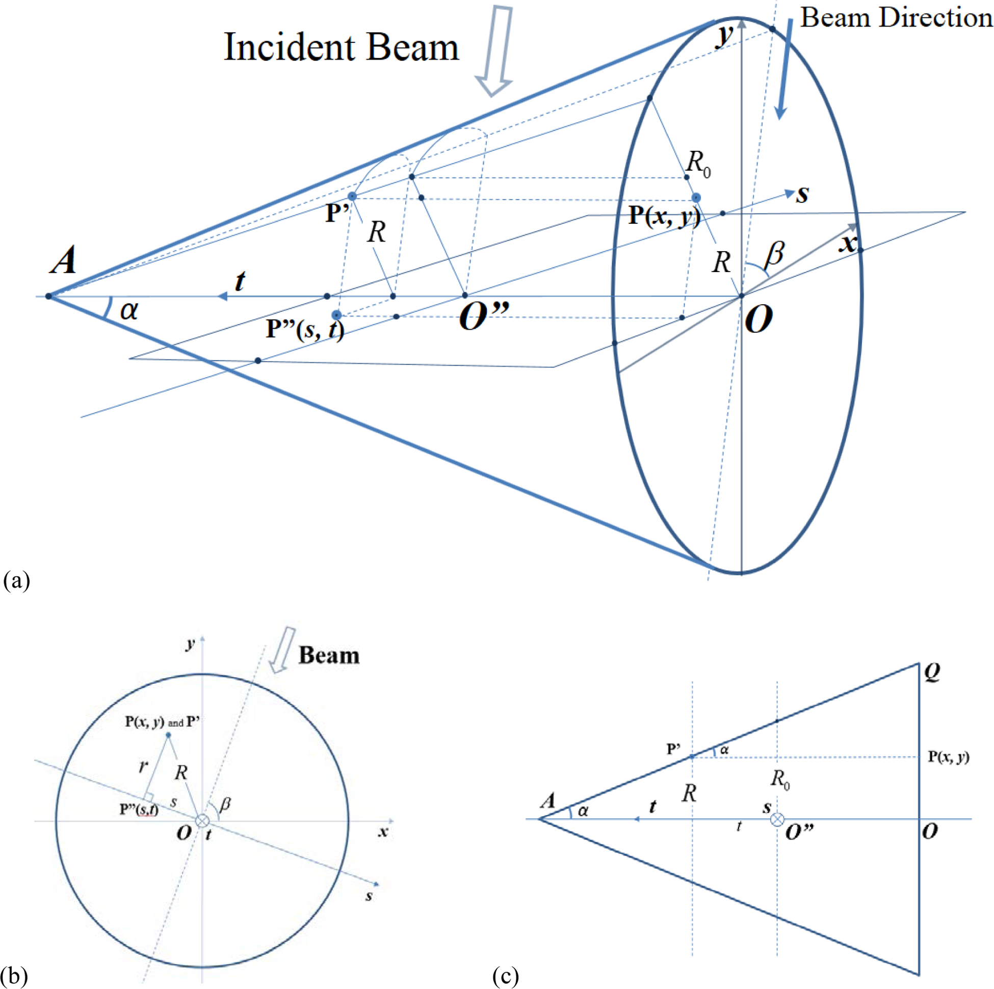
(a) shows the 3D geometry of this transform. (x, y) is the coordinate system on the orthogonal projection, the radiation beam makes an angle β with x-axis, and the BEV plane (s, t) is perpendicular to the beam. For any point P(x, y) in the orthogonal projection, the algorithm finds the imaged point P’ on the cone surface, and then its counterpart P”(s, t) in the (s, t) plane (BEV). (b) and (c) are the bottom view and the side view, respectively.
Let P’ be any point on the cone surface, then the CCD camera sees P’ as point P(x,y) in the orthogonal projection image (raw CCD image with distortion correction). Mathematically it is to project P’ onto the x-y plane along the direction parallel to the cone axis. Projecting P’ along the beam direction to the BEV plane (s, t) finds P”(s, t). Thus any point P”(s, t) in the BEV image correlates to a point P(x, y) in the orthogonal projection image, and this one-to-one mapping can be described in the following equations (Equation (i)),
| (i) |
Here the radius of P(x, y) is given by . R0 is the radius of the cone surface measured at O”, the system isocenter where t=0 and s=0. α is half cone angle and β is the beam angle. The gantry angle is 90-β for beamline x-ray and pencil beam images and is 180-β for orthogonal x-ray images. Please note that this transformation already scales all BEV images to the iso-plane.
II.D. Measurement of QA quantities
(1). Cross-hair Images
The beamline x-ray system is mounted in the PBS nozzle and another x-ray system (called the orthogonal x-ray) is mounted 90 degrees counterclockwise around the rotation axis of the gantry, i.e., the negative BEV-X direction as illustrated in Figure 1(b). A physical cross-hair plate is mounted on both x-ray sources to show the imaging field center and orientation. The cross-hair indicates the BEV-X and BEV-Y direction as defined in Figure 1(b). In the orthogonal projection image, the BEV-X hair appears as a circle, while the BEV-Y hair appears as two-line segments separated by a circular black area in the center (Figures 4(a)). The circular black area at the image center is the orthogonal projection of the cone tip area where there is no scintillation material. The incident x-ray beam angle is found from the angle of the BEV-Y cross hair (the fitted blue line). It is noted that the beam entry side is always brighter than the exit side, and this fact is used to eliminate the 180-degree ambiguity. The orthogonal projection image is then transformed into two BEV images, one from the incident beam and the other from the exiting beam (Figures 4(b) and (c)). The cross-hair center is calculated and shown in yellow mark, which is compared to the actual coordinate center shown in blue.
Figure 4.

Typical orthogonal projection images and BEV images. The first row shows x-ray cross-hair images: (a) orthogonal projection, (b) BEV of entry beam and (c) BEV of exit beam. The second row shows pencil beam spot images in the same order. Beam direction is calculated in the orthogonal projection images and is indicated by the blue line. The beam center is calculated in the BEV images and is shown against the coordinate center (big blue cross).
The accuracy of position estimates by the XRV/analysis algorithm can be validated with Cross-hair images measured at various positions of patient positioning system (PPS). While the cone-detector is initially aligned to the room lasers and the PPS is precisely shifted in any of the three directions (longitudinal, lateral and vertical), the relative magnitude of the shift can be estimated from the shift of the cross-hair in the BEV image. Beamline images at the gantry angle of 0 provide shifts along IEC-X (lateral) and IEC-Y (longitudinal) axis, and the orthogonal images give shifts along IEC-Y (longitudinal) and IEC-Z (vertical) axis.
(2). Pencil Beam Spot Images
The XRV system can be used to characterize the geometric features of a pencil beam such as the spot centricity and size. An example of the orthogonal projection image with an incident pencil beam is shown in Figure 4(d). The beam angle is the angle of the line that connects the brightness peak of the entry and the exit spot. Using this beam angle, the BEV transformation produces the entry and exit BEV images (Figure 4(e) and (f)), showing the actual shape of the pencil beam spot. The intensity distribution of the spot is then fitted using a 2D Gaussian function (Equation (ii)) to find the spot center (x0, y0) and spot size (σx and σy).
| (ii) |
Clinically, these geometrical features of pencil beam spots are routinely measured and maintained with a two-dimensional ion-chamber array (MatriXX-PT, IBA Dosimetry, Belgium). Matrixx-PT features a 32 × 32 grid of parallel plate ion-chambers with each having a diameter of 4.2mm and a height of 2.0mm. Chambers are separated by ~7.6mm spacing. The sizes of spots delivered at difference gantry angles are measured by mounting MatriXX-PT to a custom holder inserted to the gantry snout. Spot sizes measured by MatriXX-PT and XRV are compared for different proton energies and gantry angles.
(3). Winston-Lutz Test
As the cross-hair image of the beamline x-ray indicates the imaging center and the pencil beam spot image indicates the radiation center, a comparison of these two images tells the coincidence of the imaging center and radiation center at the iso-plane. This is the Winston-Lutz test for PBS treatments. The coincidence and the gantry angle dependency are especially critical for stereotactic treatments.
Each raw XRV image gives two BEV images, i.e., an entry image and an exit image, which could be slightly different due to imperfection in alignment and cone geometry. For the following sections, all quantities that are measured from BEV images, such as x-ray cross-hair center, pencil beam centricity and spot size, are given by the average over the two BEV images to reduce measurement errors and to give estimates projected at the iso-centric plane (s-t).
III. RESULTS
III.A. Validation of Position Accuracy
The accuracy of position estimates by the XRV/analysis algorithm was evaluated with cross-hair images obtained by precisely shifting XRV to various PPS positions. The PPS couch was shifted by [−4mm, −2mm, −1mm, 0mm, +1mm, +2mm, +4mm] along all the three directions (IEC-X, IEC-Y and IEC-Z), and the shifts were measured using XRV by analyzing the beamline cross-hair (IEC-X and IEC-Y) and the orthogonal source cross-hair (IEC-Z) at gantry angle 0 degree. The results are listed in Table 1. The differences between the XRV measurements and the positions given by the PPS readout are tabulated. Most errors are less than 0.2mm, and the maximum error is 0.59mm when a shift of 4mm was made along IEC-X direction.
Table 1.
PPS positioning accuracy
| PPS Shift (mm) | IEC-Y error (mm) | IEC-X error (mm) | IEC-Z error (mm) |
|---|---|---|---|
| −4.00 | 0.20 | 0.06 | 0.17 |
| −2.00 | −0.01 | 0.06 | 0.18 |
| −1.00 | 0.02 | 0.10 | 0.10 |
| 0.00 | 0.00 | 0.00 | 0.00 |
| 1.00 | −0.15 | −0.04 | 0.04 |
| 2.00 | 0.31 | −0.25 | −0.05 |
| 4.00 | 0.08 | −0.59 | −0.29 |
III.B. Imaging system QA
Gantry angles were measured from XRV images acquired using both the beamline and orthogonal x-ray systems, and the results are tabulated in Table 2. The deviations from the console readouts, which are provided by the digital encoder, to measurements were found to be no more than 0.2 degrees.
Table 2.
Gantry angle measurement using x-ray cross-hair
| Labeled Gantry Angle (Degrees) | G0 (Degrees) | G90 x-ray (Degrees) |
|---|---|---|
| 0.0 | 0.0 | 0.0 |
| 30.0 | 30.0 | 30.1 |
| 60.0 | 60.1 | 60.2 |
| 90.0 | 90.0 | 90.0 |
| 120.0 | 120.0 | 120.2 |
| 150.0 | 150.2 | 150.2 |
| 180.0 | 180.0 | 180.0 |
| 210.0 | 210.2 | 210.2 |
| 240.0 | 240.1 | 240.2 |
| 270.0 | 270.0 | 270.0 |
| 300.0 | 300.2 | 300.0 |
| 330.0 | 329.9 | 330.1 |
| 180.0E | 180.0 | 180.0 |
The offset of beam center in BEV coordinates is then converted to IEC coordinates using the following relation (Equation (iii)) where β is gantry angle:
| (iii) |
The cross-hair center as given by the DIPS system was used for comparison. As shown in Figure 5, the XRV results (red) agree well with DIPS (blue) for both beamline and orthogonal x-rays, up to a consistent small shift of (−0.5mm, 0.0mm, −0.3mm), most likely due to alignment discrepancy between the setup conditions of DIPS and XRV systems. Mechanical sagging of ~3mm was observed as the gantry rotates. It is also observed that the ‘phase’ of the orthogonal x-ray result is ~90 degree behind that of the beamline x-ray, which reflects the fact that the orthogonal x-ray source is mounted at 90 degrees counterclockwise from the nozzle.
Figure 5.

Cross-hair center measurements for both beamline and orthogonal x-ray systems. Deviations were calculated from the origin of the IEC coordinates.
III.C. Pencil beam QA
Table 3 shows the gantry angle measurements calculated from pencil beam spot images. The deviations from console readout are no more than 0.2 degrees.
Table 3.
Gantry angle measurement using PBS spots
| Labeled Gantry Angle (Degrees) | PBS Measurement (Degrees) | Error (Degrees) |
|---|---|---|
| −0.1 | −0.2 | −0.2 |
| 29.9 | 30.0 | 0.0 |
| 59.9 | 60.0 | 0.0 |
| 89.9 | 90.0 | 0.0 |
| 120.0 | 120.0 | 0.0 |
| 150.0 | 150.1 | 0.1 |
| 180.0 | 180.1 | 0.1 |
| 210.0 | 210.0 | 0.0 |
| 240.0 | 239.9 | −0.1 |
| 270.0 | 270.0 | 0.0 |
| 300.0 | 299.9 | −0.1 |
| 329.9 | 330.0 | 0.0 |
| −180.1 | 180.0 | 0.0 |
In-air PBS spot sigma is an important QA quantity that measures the pencil spot size and it is dependent on different proton energies and gantry angles. This quantity is routinely checked against the beam model in treatment planning system (TPS). Sigma values for different energies were acquired at the three cardinal angles (0°, 90° and 270°) with XRV and the averaged values are shown in Figure 6 (the red square dots). The pencil beam spot size in the BEV-X (in the plane spanned by IEC-X and IEC-Z, noted as IEC-XZ) direction ranges from 14.9mm for 87MeV to 7.6mm for 226MeV, and the size in the BEV-Y (same as IEC-Y) direction is 0.3mm smaller. Compared to the reference data measured using the MatriXX detector during the PBS commissioning, the XRV results were consistently smaller but the deviation was small, less than 0.2mm for most energies. The maximum deviation was 0.4mm at IEC-Y direction at energies 190–210 MeV.
Figure 6.

Pencil beam spot size measurements for various proton energies. Error bars on the MatriXX reference curve is +/−10%, which is our clinical tolerance for routine QA.
III.D. Winston-Lutz test
Winston-Lutz test is to evaluate the coincidence of x-ray imaging center and PBS beam center. At the same gantry angle, both imaging center and pencil beam center were measured. The deviations between the two centers are calculated and plotted as shown in Figure 7. The insert is a fused view of the x-ray cross hair image and the pencil beam spot image, showing the relative deviation of the two center positions (red for the cross-hair center and blue for the pencil beam spot center). Measurements shows that the deviation of IEC_Y ranges from −0.8mm to 0.0mm and the deviation of IEC_XZ ranges from − 0.6mm to +0.5mm. The maximum deviation was found around the gantry angle of 90 degrees.
Figure 7.

Winston-Lutz test at different gantry angles. The insert is a fused view of the x-ray cross-hair image and the pencil beam spot image, showing the relative position of the two centers (red for cross hair center and blue for pencil beam spot center).
IV. DISCUSSION
In this study, the cone-shaped scintillation detector (Logos XRV) was utilized to perform multiple IGRT QA measurements for PBS treatments. Attributed to the cone shape, QA tasks could be performed both efficiently and accurately over the entire 360-degree gantry angles. Limited by the cone size (~180mm in diameter and ~220mm in height), Logos XRV was originally designed to measure small fields (pencil beams or Cyberknife collimated beams) or small objects (around cross-hair center) which are a few centimeters in size. However, the small effective area was found sufficient for PBS IGRT QAs since almost all QA parameters are characterized around the beam center.
The validation of the positioning accuracy showed the measurement or analysis errors with respect to the shifted PPS positions. The positioning error along IEC-Y fluctuates with no clear trend, perhaps due to the lower image resolution in the BEV-Y (same IEC-Y) direction. Errors in IEC-X and IEC-Z directions generally increase with larger shifts. This may be caused by the fact that the incident cross-hair image made an angle at cone surface instead of being perpendicular to the surface, and thus the curvature of the cone surface introduced larger errors due to distortion. However, most IGRT QA parameters are defined near the iso-center and should be much closer (e.g., less than ~2mm) than the 4mm limit that we have examined in the validation.
Gantry angle could be acquired from three different type of measurements: the beamline x-ray, the orthogonal x-ray and the pencil beam spot. Based on the cross-validation with the three measurements and a comparison to the console readout, and the deviation was found to be within 0.2 degree. The centricity of both x-ray cross-hairs was significantly dependent on the gantry angle, showing a sinusoidal pattern due to the rotation of the gantry structure. The results indicated a sagging up to ~3mm at certain gantry angles. Unlike photon linear accelerators, this is not uncommon for such a big gantry structure and we require an x-ray image-based setup for every treatment beam in a clinical practice for that exact reason.
Sagging is not obvious in Winston-Lutz results. While both imaging center and pencil beam center show sinusoidal trends due to sagging, Winston-Lutz results shown in Figure 7, as the difference between the two centers, almost cancel out the trend. It is observed in Figure 7 that there are gaps of 0.3mm - 0.5mm between the measurements acquired at gantry angles 180 degree (clockwise) and 180E (counterclockwise). This can be partly explained by limited repeatability of gantry rotation, and partly due to the fact that Winston-Lutz results are expected to show accumulated uncertainties coming from both image centers and pencil beam centers.
Logos XRV gave slightly smaller pencil beam spot sizes when compared to the commissioning data by MatriXX. During commissioning, a 2D scintillator system (Beam Imaging System (BIS), Wellhöfer Dosimetrie, Schwarzenbruck, Germany) was initially used for the measurement of sigma and it agreed with the MatriXX detector within 2% (BIS was larger). The MatriXX is a suitable detector for measuring beam size because the pixel pitch, 7.6 mm, is comparable to the beam size, 1 sigma, of 8 to 15 mm. The difference could be due to the difference in the resolution of the two detectors, the insufficient number of angles measured since the commissioning model represents an average of ~12 angles, or a small drift of beam optics from the commissioning time. It is also possible that the conversion from proton intensity to scintillator light output is slightly different from the response of the MatriXX system that converts proton intensity to air ionization. However, given MatriXX detector spacing of 7.5mm and a typical σ value of 10mm, a pencil beam spot was captured by less than 6×6 pixels. Logos XRV had a resolution of 0.39mm/pixel, which was much higher and could potentially enable more accurate measurements for pencil beam profiles.
The geometric uncertainties and errors in BEV images are attributed to the non-isotropic resolution introduced in both the image correction and transformation procedures. As the calibration curve in Figure 2 is not linear, the orthogonal projection image is not strictly uniform in resolution. The resolution is slightly lower toward the image center. After the transformation, the BEV image shows better resolution in the BEV-X direction than that in the BEV-Y direction, as demonstrated in Figure 4 (b)(c)(e)(f). This is caused by the imaging geometry along the cone surface. As shown in Figure 4(d), for example, the shape of the pencil beam spot is ‘compressed’ along the longitudinal direction on cone surface because of the steep cone angle but is only slightly ‘bent’ in the lateral direction following the cone curvature. When this orthogonal projection image with isotropic resolution is transformed into a BEV image, the ‘compress’ part will be ‘extracted’ with a lower resolution while the slightly ‘bent’ part will be projected with the original resolution. Given the half cone angle of 22.5°, the resolution in BEV-Y is times lower.
V. CONCLUSION
The Logos XRV cone-shaped scintillation detector system showed advantages in performing multi-purposed measurements with a single detector setup. The scintillator screen has higher spatial resolution than MatriXX, which potentially enables more accurate measurements for pencil beams. The system is able to receive radiation from all gantry angles when sitting on the couch, also making it more convenient to check the coincidence of radiation center, laser center and imaging center. The in-house algorithms were successfully developed and implemented to measure and analyze QA parameters that are essential to PBS IGRT in a semi-automatic manner. This study presents an alternative and more efficient approach for IGRT QA for PBS and potentially for linear accelerators.
ACKNOWLDGEMENT
We acknowledge the support of the Harvard Medical Physics Residency Program at Harvard Medical School for generous support to Weixing Cai.
REFERENCES
- Bissonnette JP et al. 2012. Quality assurance for image-guided radiation therapy utilizing CT-based technologies: A report of the AAPM TG-179 Med. Phys 39(4) 1946–1963 [DOI] [PubMed] [Google Scholar]
- Bujold A, Craig T, Jaffray D and Dawson L 2012. Image-guided radiotherapy: Has it influenced patient outcomes? Semin. Radiat. Oncol 22 50–61 [DOI] [PubMed] [Google Scholar]
- Chang Z, Bowsher J, Cai J, Yoo S, Wang Z, Adamson J, Ren L and Y FF 2012. Imaging system QA of a medical accelerator, Novalis Tx, for IGRT per TG 142: our 1 year experience J. Appl. Clin. Med. Phys 13(4) 113–140 [DOI] [PMC free article] [PubMed] [Google Scholar]
- Dhanesar S et al. 2013. Quality assurance of proton beams using a multilayer ionization chamber system Med. Phys 40(9) 092102. [DOI] [PubMed] [Google Scholar]
- Kooy HM et al. 2010. A case study in proton pencil-beam scanning delivery Int. J. Radiat. Oncol. Biol. Phys 76(2) 624–630 [DOI] [PubMed] [Google Scholar]
- Lin Y, Clasie B, Lu HM, Flanz J, Shen T and Jee KW 2017. Impacts of gantry angle dependent scanning beam properties on proton PBS treatment Phys. Med. Biol 62 344–357 [DOI] [PubMed] [Google Scholar]
- Logos Systems. Proton and X-ray camera quality assurance. 2014.
- Logos Systems 2015. BeamWorks for the XRV-100 and XRV-124 User Manual (Version 2.18) pp 72–73 [Google Scholar]
- Lomax AJ et al. 2004. Treatment planning and verification of proton therapy using spot scanning: initial experiences Med. Phys 31(11) 3150–3157 [DOI] [PubMed] [Google Scholar]
- Middleton M et al. Successful implementation of image-guided radiation therapy quality assurance in the Trans Tasman Radiation Oncology Group Int. J. Radiat. Oncol. Biol. Phys 81(5) 1576–1581 [DOI] [PubMed] [Google Scholar]
- Paganetti H 2011. Proton Therapy Physics (Boca Raton, FL: CRC Press; ) [Google Scholar]
- Peng JL, Kahler D, Li JG, Amdur RJ, Vanek KN and Liu C 2011. Feasibility study of performing IGRT system daily QA using a commercial QA device J. Appl. Clin. Med. Phys 12(3) 248–256 [DOI] [PMC free article] [PubMed] [Google Scholar]
- Schreibmann E, Elder E and Fox T 2008. Automated quality assurance for image-guided radiation therapy J. Appl. Clin. Med. Phys 10(1) 71–79 [DOI] [PMC free article] [PubMed] [Google Scholar]
- Stock M et al. 2009. Image quality and stability of image-guided radiotherapy (IGRT) devices: A comparative study Radiother. Oncol 93 1–7 [DOI] [PMC free article] [PubMed] [Google Scholar]
- Veiga C et al. 2016. First clinical investigation of cone beam computed tomography and deformable registration for adaptive proton therapy for lung cancer Int. J. Radiat. Oncol. Biol. Phys 95(1) 549–559 [DOI] [PubMed] [Google Scholar]
- Wang L, Klelar KN, Mok E, Hsu A, Dieterich S and Xing L 2012. An end-to-end examination of geometric accuracy of IGRT using a new digital accelerator equipped with onboard imaging system Phys. Med. Biol 57 757–769 [DOI] [PMC free article] [PubMed] [Google Scholar]
- Wang L, Xing L and Nelson B 2014. A novel daily QA system for robotic image guided radiosurgery with variable aperture collimator Med. Phys 41(6) 330 [Google Scholar]
- Zhu M, Botticello T, Lu H-M and Winey B 2014. Long-term stability and mechanical characteristics of kV digital imaging system for proton radiotherapy Med. Phys 41(4) 041706. [DOI] [PMC free article] [PubMed] [Google Scholar]