

Abstract
A small, hermetic, wirelessly-controlled retinal prosthesis was developed for pre-clinical studies in Yucatan mini-pigs. The device was implanted on the outside of the eye in the orbit, and it received both power and data wirelessly from external sources. The prosthesis drove a sub-retinal thin-film array of sputtered iridium oxide stimulating electrodes. The implanted device included a hermetic titanium case containing the 16-channel stimulator chip and discrete circuit components. Feedthroughs in the hermetic case connected the chip to secondary power- and data-receiving coils, which coupled to corresponding external power and data coils driven by a power amplifier. Power was delivered by a 500 KHz carrier, and data were delivered by frequency shift keying. Stimulation pulse strength, duration and frequency were programmed wirelessly from an external computer system. Through an ‘outbound’ telemetry channel, electrode impedances were monitored by an on-board analog to digital converter that sampled the output voltage waveforms. The final assembly was tested in vitro in physiological saline and in vivo in two mini-pigs for up to three months by measuring stimulus artifacts generated by the implant’s current drivers.
I. Introduction
VISION prostheses are being developed by a number of groups worldwide [1–14]. These devices aim to restore visual function lost due to degenerative retinal diseases such as retinitis pigmentosa (RP) and age-related macular degeneration (AMD). These conditions cause a gradual loss of photoreceptors, yet a substantial fraction of the retinal ganglion cells remain forming an intact pathway to the visual cortex. The prevalence of RP is approximately 1 in every 4000 live births, and there are approximately 1,700,000 affected individuals worldwide. AMD is the leading cause of blindness in the developed world, with roughly 2 million affected patients in the United States alone. This number is expected to increase 50% by the year 2020 as the population ages [15]. The best existing treatments slow the progress of these diseases, but until recently there has been no known method to restore functional vision. While there is evidence that significant reorganization of the retina occurs after the loss of input signals from the photoreceptors [16], our group and others have nevertheless shown that focal electrical stimulation of retinal ganglion cells yields responses corresponding to the strength and location of the stimuli [17]. Our group showed the retinal prosthesis concept in six acute human retinal stimulation trials, in which microfabricated thin-film electrode arrays were surgically inserted into the subjects’ eyes, resting on or just above the epi-retinal surface. An external stimulator system [18] delivered current pulses for a few hours through connections through the eye, and subjects reported their perceptions [4, 5]. These experiments led us to begin the development of three generations of chronically-implantable retinal prostheses to fully explore the prospects of restoring useful vision.
Other groups are engaged in similar efforts [10–14], most developing either epi-retinal [6], [7] (on the front of the retina inside the eye) or sub-retinal [8], [9] (behind the retina, between the retina and choroid) devices. Others focus on less direct stimulation of the retina using a suprachoroidal (behind the choroid, between the choroid and the sclera) or a trans-scleral (outside of all or part of the sclera) approach [10–12]. Our team began with an epi-retinal approach, used in the acute human surgical trials described above [4, 5], but has changed to an ab externo (or ‘from the outside’) subretinal surgical approach to the retina. This more challenging surgical technique results in improved biocompatibility and a less invasive surgery, and it leaves the bulk of the implant device outside the eye.
Our first-generation wirelessly-powered chronic retinal stimulation device [1] was implanted in Yucatan mini-pigs during the spring and summer of 2008. We describe here how this initial implant has been improved in successive generations of the Boston retinal prosthesis; circuits have been encased in a hermetic titanium enclosure, the coils were moved to a more magnetically-favorable position on the eye, and surgical access for electrode array insertion has been improved. We also describe our power and data telemetry systems, and we describe the engineering improvements that underlie our high-density prosthesis for human use that is currently under development.
II. Implant Design
A. System Description
Our retinal prosthesis system includes an external computer-based controller with a user interface for selecting which electrodes to drive and with what level of current. Data from the computer system were sent to a power amplifier, which then transmitted wirelessly to the implant by near-field inductive coupling. Our initial custom integrated circuit [19], fabricated in 0.5 μm CMOS, received and decoded the incoming data and delivered stimulating current to the appropriate electrodes based on the timing of transmitted commands. The chip was capable of delivering up to 930 μA of current per channel at steps of 30 μA; its power supplies operated at +/− 2.5 V and were regulated by a parallel 5.1 V Zener diode. This circuit was designed to be an extremely flexible research tool, and was capable of delivering more current than was needed for this animal work. Currents typically delivered to electrodes ranged from 30 to 240 μA. The chip consumed 1.3 mW, excluding current sources. In typical stimulation modes (180 μA, 1 ms per phase biphasic pulses, repeated every 20ms), the total implant power consumption was approximately 2 mW. The chip’s electrical stimulation current was delivered to the retinal nerve cells via a thin-film microfabricated array containing sputtered iridium oxide film (SIROF) electrodes, which was surgically inserted into the subretinal space through a flap in the sclera.
In a future clinical implant, patients will wear a camera mounted on glasses to survey the visual scene, and will carry a small battery-powered controller which will perform the required image signal processing, intelligently extracting features from a megapixel image and re-creating that image for an implant containing dozens or hundreds of electrodes.
B. Differences from First-Generation Device
Our first-generation implant [1] was assembled on a flexible substrate that wrapped around the eye inside the socket, attaching to the sclera of the eye (Fig. 1). This device had three significant design drawbacks: (1) small receiver coils limited power and data telemetry effectiveness due to poor coupling; (2) the silicone coating held up well in studies of up to 10 months, but did not appear to be viable for chronic trials of 5–10 years; and (3) the required surgical approach for electrode array insertion was very challenging, due to the need to insert the array through the center of the coils. In addition, the power and data telemetry amplifiers used with the first-generation device had limited range and reliability.
Fig. 1.

First-generation Boston retinal prosthesis.
Our newer-generation device [2], [3] used the same controller chip [19] and power and data telemetry scheme, but solved the 3 problems outlined above with, respectively: (1) larger coils that were implanted on the front of the eye, surrounding the cornea, but under the conjunctiva. The coils were also wound on a spherical form so as to fit the curvature of the eye; (2) a hermetic, titanium case enclosed the electronic circuitry. This case was attached to the sclera deep in the superior-nasal quadrant of the eye orbit; and (3) a serpentine electrode array which extended from the hermetic case, under the superior rectus muscle, over to the superior-temporal quadrant. This allowed better surgical access to create the scleral flap and insert the array from the outside into the sub-retinal space. An example of this hermetic implant is shown in Fig. 2. The external power and data transmitters were also redesigned to provide increased telemetry distance and startup reliability.
Fig. 2.
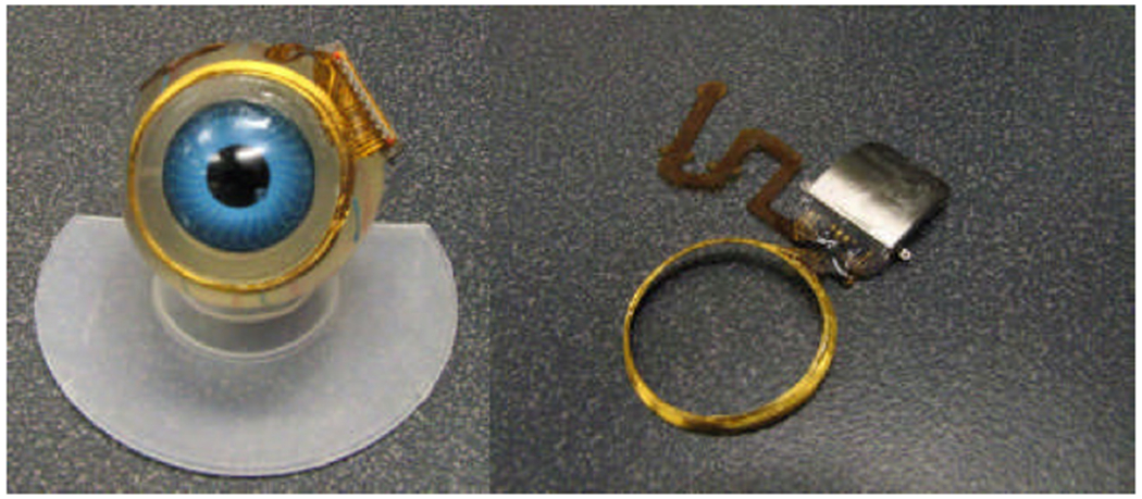
Second-generation hermetically-packaged 16-channel Boston retinal prosthesis.
C. Improved Implant Components
Relocating the secondary power and data coils from the temporal side of the eye to the anterior of the eye allowed for much larger coils, giving much better inductive coupling. However, these coils rested against the delicate conjunctiva and can wear through and become exposed, creating a risk of infection. To reduce this risk, the coils were carefully wound on a steel sphere so that they matched the curvature of the eye. The secondary coils included separate power and data windings and leads, but they were wound together for structural support and ease of implantation. They were made of 40 AWG gold magnet wire, with 28 turns for the 32 μH power coil and two 6-turn coils for a 12-turn center-tapped 4.5 μH data receiver. The spherically-molded coil had a mean radius of 9.5 mm and a height off of the eye of less than 0.2 mm. The secondary coils are shown on a model eye in Fig. 2. The primary coils sat in front of the eye, and were made of separate power and data coils in a molded poly(dimethylsiloxane) body. The primary power coil had a mean radius of 19 mm, while the data coil had a mean radius of 12.5 mm. The primary coils are also shown in Fig. 3 atop the device under test.
Fig. 3.
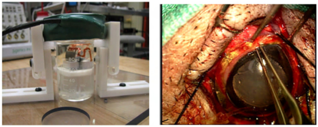
Left: in vitro test setup for the retinal prosthesis. Right: Implantation of the updated device around the cornea of a minipig.
The implant’s electronic circuitry was encased in the titanium enclosure, which measured 11 mm x 11 mm x 2 mm and was curved to conform more closely to the eye surface. A small ceramic header, 8.8mm x 1 mm x 1 mm thick, had 19 staggered holes drilled in it, and titanium pins 3.3 mm long were inserted through the holes. Gold rings were fitted around the titanium pins and brazed to the ceramic for an airtight seal. A curved frame was machined from titanium, and the ceramic feedthrough with a gold strip around its edge was brazed into the case. The integrated circuit, which includes the telemetry receiver, digital controller, analog current sources, biases, and startup circuitry, was flip-chip bonded to a circuit board. Additionally, Schottky rectifier diodes, two power supply capacitors, a discrete resistor and capacitor for power-up reset delay, and a resonating capacitor for the power secondary coil were added; an on-chip power clamp was used for power supply regulation. The pads on the top and bottom of the edge of the board were soldered to the interior pins of the feedthrough, and ground pads at the two corners opposite the feedthroughs were soldered to pins welded to the case, allowing the titanium case itself to serve as a current return counter electrode for stimulation. The assemblies were baked for 24 hours to drive off residual water, then titanium lids were laser-welded onto the top and bottom of the case in a helium/argon ambient environment. Hermeticity was evaluated using a Varian helium leak detection system, and leakage rates lower than 1x10⁻⁹ std cc He/sec were considered passing. With this leakage rate, the projected lifetime of the packaged system is estimated to be several years. No desiccant was added to this device, but one may be incorporated into future versions. Before being welded to the implant case, the top and bottom lids were sputtered with platinum to improve the current-carrying effectiveness of the case. The external feedthrough pins were soldered to the external flex circuit with gold-tin solder, and an epoxy header was molded over the external feedthrough connections.
The novel, serpentine design of our flexible, thin-film 16 μm thick polyimide array of 400 μm diameter SIROF electrodes allowed the surgeon to route it under the superior rectus muscle and insert the electrodes into the subretinal space in the superior-temporal quadrant. Since the titanium case was in the superior-nasal quadrant and the secondary coil was low-profile, there was nothing blocking surgical access to the area of the eye where the sclera flap was made to insert the array. The retina was first separated from the choroid with a bleb of fluid injected from inside the eye, then the array was inserted into the bleb space. The retina slowly settled on top of the array and held it in place [20], [21]. The placement of the electrode array in the subretinal space took advantage of the eye’s natural forces holding the retina against the choroid. The array was sutured to the sclera just outside the point where it enters the eye, but no attachment was necessary in the subretinal space.
III. Testing Methods
The full implant system was tested dry on the bench, as well as in vitro in a phosphate buffered saline solution. On the lab bench, dry testing was performed by connecting to the device though a polyimide test tail that was fabricated as part of the external flex and electrode array. Electrode loads, each consisting of a resistor in series with a parallel resistor-capacitor pair, were attached to the current source outputs. Power and stimulation commands were transmitted to the device over distances ranging between 5 mm and 30 mm, and balanced biphasic current pulses ranging from 30 to 240 μA were delivered to the mock electrode loads with pulse durations of 1 ms (24-192 μC/cm2). The load voltage was directly measured and recorded during wireless operation of the device. During in vitro testing, the device was attached to a plastic model eye, as in Figs. 2 and 3, and submerged in a saline bath.
Devices were implanted in two minipigs, each weighing roughly 20 kg. Electroretinograms (ERGs) were taken preoperatively to assess the general health of each pig’s retina, and they were also taken at the beginning of subsequent exams. After surgery, primary telemetry coils were then placed near the front of the animal eyes. Power and data were delivered to the implant and adjusted until the recording electrode showed stimulus artifact from the pulsing current sources of the implant. Control measurements were made by transmitting power and data to the implant, but commanding zero stimulation current. Photographs of hermetically-packaged retinal prostheses during in vitro testing and implantation are shown in Fig. 3.
Follow-up exams were conducted on the animals one week after implantation and approximately every three to four weeks thereafter, in which the pigs were anesthetized and ERG recordings and additional sampled electrode voltage waveforms were measured.
IV. Results
Recorded electrode waveforms made by outbound telemetry from an onboard analog to digital converter on the revised stimulator chip are shown in Fig. 4. The electrode voltage was sampled progressively while stepping through the bi-phasic current pulse cycle. The higher electrode voltage seen at 9 and 21 days post-operation is consistent with earlier observations that impedance of the electrode-tissue interface is lower when measured in vitro.
Fig. 4.

Sampled electrode voltage waveforms measured by on-board analog to digital converter in vitro and in vivo 9 and 21 days post-operation.
We have also improved our surgical techniques, particularly by separate suturing of Tenon’s capsule and the conjunctiva following implantation of our device. This procedure improved the minipig’s response to the presence of the implant compared to earlier surgeries, and no postoperative exposure of implant components (which could lead to infection) has been noted of late.
V. Conclusion
Generations of wirelessly-driven retinal prosthesis devices has been developed and tested in vitro and in vivo in Yucatan minipigs. Operation of the implants have been verified in the minipig eye for up to five and a half months.
The devices presented here are capable of being implanted for a much longer time than our first generation PDMS-coated device. Accelerated in vitro testing of the hermetically-packaged implants has shown that our updated device exceeds the 5-10-year survivability requirement proposed by the FDA. Further implant modifications are now underway that will allow longer-term animal implantation trials in the near future, with a view toward human clinical trials of a device having more than 200 output electrodes.
Acknowledgment
The authors acknowledge technical support and assistance from T. Plante, S. Behan, J. Dumser, G. Swider, B. Yomtov, and J. Loewenstein, as well as administrative support from K. Quinn, P. Davis, J. Palumbo, and G. Galanek. The authors acknowledge C. Pina, W. Hansford, and MOSIS for foundry services in support of their research, as well as the Cornell NanoScale Science and Technology Facility (CNF).
This work was supported in part by the U.S. Department of Veterans Affairs, Rehabilitation Research and Development Division, through Center of Excellence grant C4266-C. Additional support was provided by NIH grant EY016674 to Prof. Wyatt at MIT, by the NSF’s support of the Cornell NanoScale Facility, by the Massachusetts Lions Foundation, and by private sources.
Contributor Information
Joseph F. Rizzo, III, Boston VA Healthcare System, 150 S. Huntington Ave., Boston, MA 02130; Massachusetts Eye and Ear Infirmary, Boston, MA 02114.
Douglas B. Shire, Boston VA Healthcare System, 150 S. Huntington Ave., Boston, MA 02130.
Shawn K. Kelly, Boston VA Healthcare System, 150 S. Huntington Ave., Boston, MA 02130.
Phil Troyk, Illinois Institute of Technology, Chicago, IL 60616.
Marcus Gingerich, Boston VA Healthcare System, 150 S. Huntington Ave., Boston, MA 02130.
Bruce McKee, Boston VA Healthcare System, 150 S. Huntington Ave., Boston, MA 02130.
Attila Priplata, Boston VA Healthcare System, 150 S. Huntington Ave., Boston, MA 02130.
Jinghua Chen, Massachusetts Eye and Ear Infirmary, Boston, MA 02114.
William Drohan, Boston VA Healthcare System, 150 S. Huntington Ave., Boston, MA 02130.
Patrick Doyle, Boston VA Healthcare System, 150 S. Huntington Ave., Boston, MA 02130.
Oscar Mendoza, Massachusetts Institute of Technology, Cambridge, MA 02139.
Luke Theogarajan, University of California, Santa Barbara, CA 93106.
Stuart Cogan, EIC Laboratories, Inc., Norwood, MA 02062 USA.
John L. Wyatt, Massachusetts Institute of Technology, Cambridge, MA 02139.
References
- [1].Shire DB, Kelly SK, Chen J, Doyle P, Gingerich MD, Cogan SF, Drohan W, Mendoza O, Theogarajan L, Wyatt JL, Rizzo JF, “Development and Implantation of a Minimally-Invasive, Wireless Sub-Retinal Neurostimulator,” IEEE Trans. Biomed. Eng, vol. 56, No. 10, October 2009, pp. 2502–2511. [DOI] [PMC free article] [PubMed] [Google Scholar]
- [2].Kelly SK, Shire DB, Chen J, Doyle P, Gingerich MD, Drohan WA, Theogarajan LS, Cogan SF, Wyatt JL, Rizzo JF, “The Boston Retinal Prosthesis: A 15-Channel Hermetic Wireless Neural Stimulator,” IEEE ISABEL conference, Bratislave, Slovak Republic, 2009. [Google Scholar]
- [3].Kelly SK, Shire DB, Chen J, Doyle P, Gingerich MD, Drohan WA, Theogarajan LS, Cogan SF, Wyatt JL, Rizzo JF, “Realization of a 15-Channel, Hermetically-Encased Wireless Subretinal Prosthesis for the Blind,” in Proc. IEEE Engineering in Medicine and Biology Conference, Minneapolis, MN, 2009, pp. 200–203. [DOI] [PMC free article] [PubMed] [Google Scholar]
- [4].Rizzo JF III, Wyatt J, Loewenstein J, Kelly S, and Shire D, “Perceptual Efficacy of Electrical Stimulation of Human Retina with a Microelectrode Array During Short-Term Surgical Trials,” Invest. Ophthalmol. Vis. Sci, vol. 44, 2003, pp. 5362–5369. [DOI] [PubMed] [Google Scholar]
- [5].Rizzo JF III, Wyatt J, Loewenstein J, Kelly S, and Shire D, “Methods and Perceptual Thresholds for Short-Term Electrical Stimulation of Human Retina with Microelectrode Arrays,” Invest. Ophthalmol. Vis. Sci, vol. 44, 2003, pp. 5355–5361. [DOI] [PubMed] [Google Scholar]
- [6].Yanai D, Weiland JD, Mahadevappa M, Greenberg RJ, Fine I, Humayun MS, “Visual Performance Using a Retinal Prosthesis in Three Subjects with Retinitis Pigmentosa,” Am. J. Ophthalmol, vol. 143, 2007, pp.820–827. [DOI] [PubMed] [Google Scholar]
- [7].Gerding H, Benner FP, Taneri S, “Experimental Implantation of Epiretinal Retina Implants (EPI-RET) With an IOL-Type Receiver Unit,” J. Neural Eng, vol. 4, 2007, pp. S38–S49. [DOI] [PubMed] [Google Scholar]
- [8].DeMarco PJ Jr., Yarbrough GL, Yee CW, Mclean GY, Sagdullaev BT, Ball SL, McCall MA, “Stimulation via a Subretinally Placed Prosthetic Elicits Central Activity and Induces a Trophic Effect on Visual Responses,” Invest. Ophthalmol. Vis. Sci, vol. 48, 2007, pp. 916–926. [DOI] [PubMed] [Google Scholar]
- [9].Schanze T, Sachs HG, Wiesenack C, Brunner U, Sailer H, “Implantation and Testing of Subretinal Film Electrodes in Domestic Pigs,” Exp. Eye Res, vol. 82, 2006, pp. 332–340. [DOI] [PubMed] [Google Scholar]
- [10].Zhou JA, Woo SJ, Park SI, Kim ET, Seo JM, Chung H, Kim SJ, “A Suprachoroidal Electrical Retinal Stimulator Design for Long-Term Animal Experiments and In-Vivo Assessment of Its Feasibility and Biocompatibility in Rabbits,” J. Biomed. Biotech, vol. 2008, pp. 547428-1–547428-10. [DOI] [PMC free article] [PubMed] [Google Scholar]
- [11].Wong YT, Dommel N, Preston P, Hallum LE, Lehmann T, Lovell NH, Suaning GJ, “Retinal Neurostimulator for a Multifocal Vision Prosthesis,” IEEE Trans. Neural Syst. Rehab. Eng, vol. 15, 2007, pp. 425–434. [DOI] [PubMed] [Google Scholar]
- [12].Terasawa Y, Tashiro H, Uehara A, Saitoh T, Ozawa M, Tokuda T, Ohta J, “The Development of a Multichannel Electrode Array for Retinal Prostheses,” J. Artif. Organs, vol. 9, 2006, pp. 263–266. [DOI] [PubMed] [Google Scholar]
- [13].Hornig R, Zehnder T, Velikey-Parel M, Laube T, Feucht M, Richard G, “The IMI Retinal Implant System,” in Humayun MS, Weiland JD, Chader G, Greenbaum E, eds., Artificial Sight: Basic Research, Biomedical Engineering, and Clinical Advances, New York: Springer, 2007, pp. 111–128. [Google Scholar]
- [14].Zrenner E, “Restoring Neuroretinal Function: New Potentials,” Doc. Ophthalmol, vol. 115, 2007, pp. 56–59. [Google Scholar]
- [15].Friedman D, O’Colmain B, Munoz B, Tomany SC, McCarty C, de Jong PT, Menesure B, Mitchell P, Kempen J, “Prevalence of Age-Related Macular Degeneration in the United States,” Arch. Ophthalmol, vol. 122, 2004, pp. 564–572. [DOI] [PubMed] [Google Scholar]
- [16].Marc RE, Jones BW, Anderson JR, Kinard K, Marshak DW, Wilson JH, Wensel TG, Lucas RJ, “Neural Reprogramming in Retinal Degenerations,” Invest. Ophthalmol. Vis. Sci, vol. 48, 2007, pp. 3364–3371. [DOI] [PMC free article] [PubMed] [Google Scholar]
- [17].Jensen RJ, Rizzo JF III, “Responses of Ganglion Cells to Repetitive Electrical Stimulation of the Retina,” J. Neural Eng, vol. 4, 2007, pp. S1–S6. [DOI] [PubMed] [Google Scholar]
- [18].Kelly SK, “A System for Electrical Retinal Stimulation for Human Trials,” M.Eng. Thesis, Massachusetts Institute of Technology, 1998. [Google Scholar]
- [19].Theogarajan LS, “A Low-Power Fully Implantable 15-Channel Retinal Stimulator Chip,” IEEE J. Solid-State Circuits, vol. 43, 2008, pp. 2322–2337. [Google Scholar]
- [20].Chen J, Shah HA, Herbert C, Loewenstein JI, Rizzo JF, “Extraction of a Chronically-Implanted, Microfabricated, Subretinal Electrode Array,” Ophthalmic Res., vol. 43, No. 3, 2009, pp. 128–137. [DOI] [PubMed] [Google Scholar]
- [21].Chen J, Doyle P, Cai C, Dumser J, Akhmechet R, Gingerich MD, Kelly SK, Shire DB, Rizzo JF, “Surgical Implantation of 1.5 Generation Retinal Implant in Minipig Eyes,” Invest. Ophthalmol. Vis. Sci, vol. 51, E-abstract 3052, 2010. [Google Scholar]