Abstract
As the demand for organ transplants continues to grow faster than the supply of available donor organs, a new source of functional organs is needed. High resolution high throughput 3D bioprinting is one approach towards generating functional organs for transplantation. For high throughput printing, the need for increased print resolutions (by decreasing printing nozzle diameter) has a consequence: it increases the forces that cause cell damage during the printing process. Here, a novel cell encapsulation method provides mechanical protection from complete lysis of individual living cells during extrusion-based bioprinting. Cells coated in polymers possessing the mechanical properties finely-tuned to maintain size and shape following extrusion, and these encapsulated cells are protected from mechanical lysis. However, the shear forces imposed on the cells during extrusion still cause sufficient damage to compromise the cell membrane integrity and adversely impact normal cellular function. Cellular damage occurred during the extrusion process independent of the rapid depressurization.
Keywords: photopolymerization, extrusion, shear, encapsulation, hydrogel
1.1. INTRODUCTION
The ability to fabricate large, vascularized tissues by bioprinting lags behind less complex structures owing to the fundamental connection between print rate, feature size, and cellular damage [1–4]. In the context of biomanufacturing processes, mammalian cells are incredibly fragile. Any exposure to mechanical forces can result in irreparable damage [1–3] or phenotypic changes [4] to the cells themselves, complicating the goal of positioning healthy, normal-functioning cells into an artificial tissue scaffold. Extrusion-based bioprinters use pressure driven flow to print a large range of bioinks and cell densities [5–7]. Cell-laden inks are typically bioprinted with 150–300 μm diameter nozzles at flow rates on the order of 1–10 μL/min [8–11]. At these nozzle diameters, single cell resolution is not feasible, and at these print rates, it would take ~102 days to print a heart-sized structure. During extrusion, bioinks with cells experience a high pressure prior to entering the nozzle where the pressure continuously drops to atmospheric levels upon exiting the nozzle. This rate and magnitude of the pressure change is dictated by the print speed and resolution. An increase in either print speed or feature resolution (smaller nozzle diameter) will also increase the rate of depressurization of the cells and the magnitude of shear stresses within the flow environment (Figure 1). As a result, any increase in print rate must be compensated by an increase in nozzle and feature size to maintain the health of the printed cells. Similarly, a decrease in nozzle diameter for high resolution printing will require a decrease in volumetric print rate to minimize cellular damage. As a result, the field of bioprinting has a fundamental print speed and resolution limit based on the mechanical integrity of the cell.
Figure 1:
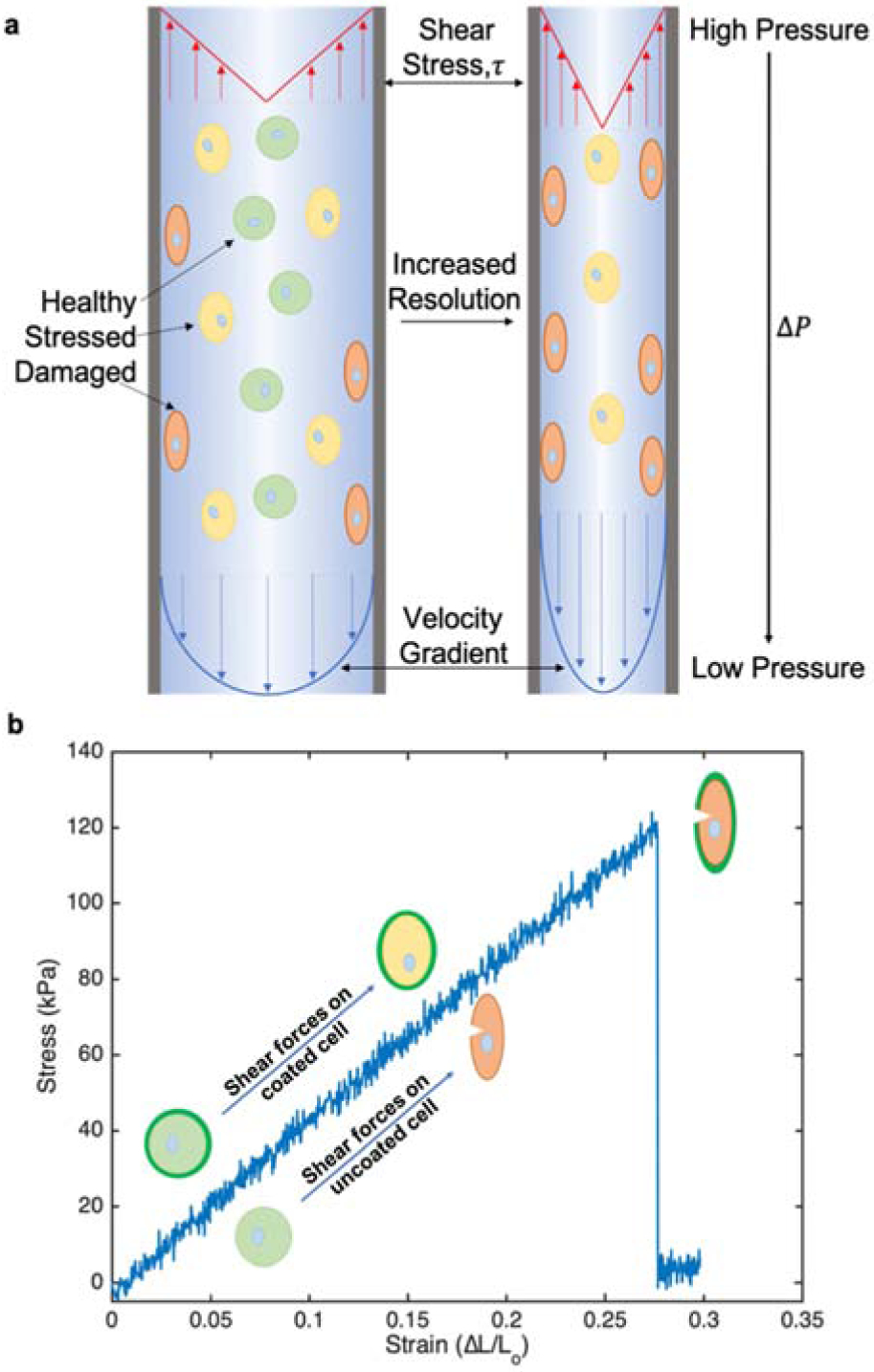
a) Schematic representation of cell deformation due to mechanical forces during extrusion printing. As printing resolution increase from left to right with constant flow rates, fluid velocity increases along with shear stress, τ, and pressure drop, ΔP. b) Stress/strain curve of PEGDA 2000 hydrogel with representation of coated and uncoated cell deformation under increasing shear stress.
The mechanical protection of cells in bioprinting has been previously accomplished with the embedding of cells into multicellular aggregates [12–14]. The use of these large structures insulates the cells from the harsh physical stresses generated in the local bioink environment [14–15], but also impose an artificial feature size limit associated with the scale of the aggregate that precludes printing at a single cell resolution. The protection of cells from mechanical damage while not dramatically altering the print resolution would dramatically advance the utility of existing bioprinters for large structures at a high resolution.
Previous studies established novel approaches to apply thin, mechanically protective coatings on cells. By coating individual cells with a 200 nm layer of crosslinked hydrogel, the cells are resistant to hypotonic lysis [16]. Under hypotonic conditions, the osmotic pressure drives water through the cell membrane and the cell swells. If the osmotic force is greater than the biological forces supporting the cell membrane, the cell lyses. The polymer coating on the cell allowed the passage of water into the cell, but the mechanical reinforcement of the cell membrane prevents the expansion and rupture of the cell in pure deionized water. These ultra-thin coatings do not dramatically alter the size of the cell, yet provide mechanical reinforcement of the cell’s peripheral membrane.
Here, the ability of thin cellular coatings to protect of cells against extrusion-related membrane damage is evaluated. Cell protection is quantified based on membrane integrity (ethidium permeation assay), cell proliferation (MTT assay), and a flow cytometric measurement of complete cellular lysis. Each cellular protection metric is related to the conventional material properties of the bulk hydrogel material. To determine any potential for increased print rates at high resolution, these phenomena are intentionally studied in conditions harsher than those used in conventional bioprinting.
To date, all studies on bioprinting-induced cell damage focus exclusively on the adverse impact of shear stress while ignoring the possibility that rapid depressurization may be a contributing factor. Rapid depressurization of cells is a common cell lysis approach used in the generation of cell-derived vesicles [17, 18]. In pressure driven flow, the presence of shear and depressurization are intimately coupled, so determining the contributions of these potentially damaging factors to cell damage requires subjecting the cells either to shear in the absence of rapid depressurization or to rapid depressurization without any fluidic shear. In all, the evaluation of coated and uncoated cells in these diverse environments substantially advances our understanding of the origin of cellular damage during bioprinting.
2.1. Materials and Methods:
2.1.1. Cell culture:
Rat cardiac myoblasts (H9C2, ATCC CLR-1446) were cultured in Dulbecco’s modified eagle medium (DMEM, HyClone) supplemented with 10% fetal bovine serum (FBS, VWR) and 1% penicillin/streptomycin (VWR) at 37°C and 5% CO2. Cells were seeded T-75 cm2 tissue culture flasks (VWR) for 48–72 h and grown to 80–95% confluence prior to use. Cells were harvested using 0.25% Trypsin-EDTA 1X (VWR) for 90 s. Then, cells were collected and resuspended in 5 mL medium to neutralize the trypsin. Cells were then pelleted at 400xg and 4 °C for 3 min, washed three times in 1 mL phosphate buffered saline 1X (PBS), and finally resuspended in PBS (HyClone) in preparation for experiments.
2.1.2. Poly(ethylene glycol) diacrylate synthesis:
Three different molecular weight poly(ethylene glycol) diacrylates (PEGDA) were synthesized as previously reported [16]. In general, all the glassware was oven-dried overnight prior to use. Poly(ethylene glycol) with three different average molecular weight [PEG; Mn ~ 1000 (Alfa Aesar), 2000 (EMD Millipore) or 3350 (Sigma Aldrich)] were subjected to acrylation. PEG (40 g) was added to a round bottom flask equipped with an addition funnel and an inlet for ultra-pure N2. Anhydrous DCM (100 mL) was added to the flask, and the flask was stirred to dissolve PEG under N2. The flask was then placed in ice bath. A molar ratio of 1:4:4 of PEG:acryloyl chloride (AC, Alfa Aesar):triethylamine (TEA, Alfa Aesar) was used for acrylation of the PEG.
First the calculated amount of AC (3.9 mL for PEG 3350, 6.5 mL for PEG 2000 or 13 mL for PEG 1000) was injected to the addition funnel containing anhydrous DCM (20 mL for PEG 3350, 30 mL for PEG 2000 or 40 mL for PEG 1000). The desired amount of TEA (6.7 mL for PEG 3350, 11.1 mL for PEG 2000 or 22.3 mL for PEG 1000) was quickly added directly to the round bottom flask containing the starting PEG solution under continuous stirring and flow of N2.
The AC/DCM solution was then added dropwise (~1 drop every 5 secs) from the addition funnel. Once the addition was complete, the continuous flow of N2 was replaced by a balloon filled with the ultra-pure N2 and the flask covered with aluminum foil and allowed to react overnight. The resulting pale-yellow mixture was filtered and then was washed with DCM to remove the bulk of the precipitated TEA salts during the reaction. A 10-fold molar excess sodium carbonate was added to the filtered solution, and the slurry was stirred vigorously for 1 hour. The mixture was then again filtered and washed with DCM to remove the insoluble sodium carbonate. The resulting DCM solution was then passed through a plug of alumina to remove the remaining impurities and plug washed with excess DCM. The resulting DCM solution was again passed through another alumina plug to remove any remaining (yellow) impurities if still present. The final DCM solution (colorless) was then evaporated to reduce the volume (~50 mL), and cold diethyl ether (400 mL) was added to precipitate the PEG diacrylate product. The mixture was kept at 4 °C for at least 1 h for acrylated PEG 3350 and 2000 to allow complete precipitation. The mixture was kept at 4 °C for overnight for acrylated PEG 1000 to allow full precipitation and solidification. The resulting white precipitate was then collected under vacuum filtration and dried on Schlenk line and analyzed by 1H NMR. The process of dissolving the PEGDA product in DCM, precipitating in cold ether followed by filtration and drying can be repeated to further remove any impurities if needed. 1H NMR data reported below for all synthesized reagents.
Poly(ethylene glycol) diacrylate 1000: 11 g (25%). Colorless liquid. 1H NMR (400 MHz, CDCl3) δ 3.65 (brs, 45H), 4.27 (m, 2H), 5.79 (dd, 1H), 6.11 (m, 1H), 6.38 (dd, 1H).
Poly(ethylene glycol) diacrylate 2000: 16 g (35%). White powder. 1H NMR (400 MHz, CDCl3) δ 3.63 (brs, 99H), 4.27 (m, 2H), 5.80 (dd, 1H), 6.11 (m, 1H), 6.38 (dd, 1H).
Poly(ethylene glycol) diacrylate 3350: 17 g (42%). White powder. 1H NMR (400 MHz, CDCl3) δ 3.62 (brs, 170H), 4.30 (m, 2H), 5.83 (dd, 1H), 6.14 (m, 1H), 6.42 (dd, 1H).
2.1.3. Cell encapsulation:
Five different polymers were evaluated for their ability to serve as a protective coating for cells against a high shear extrusion environment. All formulations contained equal amounts of the co-initiator triethanolamine (TEA, Sigma >99%) and co-monomer vinyl pyrrolidinone (VP, Sigma >99%) at 35 mM each. PEGDAs 700 (Sigma), 1000, 2000, and 3350 were all used at 25% wt/v, and the fifth formulation was 1% wt/v of PEGDA 3350 with 3% wt/v gelatin methacryloyl (GelMA) (BioBots). The formulation containing GelMA and PEGDA 3350 is denoted as GelMA/3350. PEGDA 1000, 2000 and 3350 were all synthesized in house as described above. Suspended cells were pre-labeled with a nucleic acid stain to improve cell quantitation throughout the cell-fragmenting process. Cells were incubated in 5 μM deep red nucleic acid stain (SYTO 62, Invitrogen) for 5 min on ice, washed 2x in PBS and resuspended in PBS. Samples were split into 1.5 million cell aliquots for encapsulation. Biotin was covalently bound to cell surface proteins using a biotin-succinimidyl ester conjugate (NHS-biotin; EZ-link Sulfo-NHS-LC-Biotin, Thermo Fisher). Cells were incubated in 250 μL of 0.55 mg/mL NHS-biotin for 40 min on ice, then washed 3x in PBS. Eosin was then conjugated to the cells using an in-house synthesized streptavidin (SA, Thermo Fisher)-eosin isothiocyanate (EITC, Sigma) conjugate (SA-EITC, synthesized as previously described [19]). Cells were incubated in PBS containing ~30 μg/mL SA-EITC for 30 min on ice covered from light. The sample was then washed 3x in PBS before introduction to the macromer solution. After the final wash in PBS, cells were pelletized, aspirated, and resuspended in 350 μL of macromer solution. This solution was transferred to a chip clip (Whatman) containing a glass slide and placed in a chamber constructed of two 150 mm clear polypropylene tissue culture dishes. This chamber was purged with nitrogen using a water bubbler for 5 min at a flow rate of 0.8 standard L/min before irradiation. During irradiation, nitrogen flow rate was reduced to 0.2 standard L/min to reduce evaporation of the sample. The cells were irradiated with a 530 nm collimated LED lamp (Thorlabs) at 35 mW/cm2 for 10 min for the surface polymerization reaction. After polymerization, the cells were removed by pipette and the chip clip was washed 2x with 500 μL PBS. The glass slide was then removed and scraped with a cell scraper to ensure maximum cell recovery. Cells were washed 2x in PBS and strained with a 40 μm cell strainer (VWR) to remove any cell aggregates and bulk polymer particles prior to extrusion.
2.1.3.1. Fluorescent Polymerization
Polymer coated H9C2 cells were imaged using fluorescent microscopy. Prior to polymerization, the cells were first incubated with 5 μg/mL Hoechst stain for 20 min, then washed 3x in PBS. Yellow-green FluroSphere nanoparticles (Thermo) were added to the monomer solutions of PEGDA 700, 1000, 2000, and 3350 at a concentration of 0.5 wt%. Polymerization was then performed as described above. For GelMa imaging, cells were stained with primary anti-collagen 1 antibody (Abcam) followed by secondary Alexa 647 (AF-647) antibody (Invitrogen).
2.1.4. Swelling properties:
The swelling ratio of each polymer was determined in deionized water (diH20). Macromer formulations were supplemented with 1 mM EITC in DMSO at a 1:10 dilution for a final EITC concentration of 0.1 mM. Each sample was subjected to the same nitrogen and irradiation conditions as cell coating experiments above. Bulk gels were formed in a chip clip on a glass slide using a 16 well clip. Aliquots (75 μL) of macromer solution were placed in a well for polymerization. The chip clip containing the macromer solution was then irradiated with 530 nm light for 10 minutes. Upon the formation of bulk hydrogel, the gel was placed in 4 mL of deionized water for 4–8 h on a rocker table to allow for complete saturation. Gels were removed from water, patted to remove excess water and weighed in their swollen state. All gels were then placed under vacuum for ~24 h and weighed again in their dry state.
2.1.5. Mechanical Properties:
Uniaxial tensile testing was performed on each polymer type. Films were generated in 9×9 cm square tissue culture dish at ~1 mm thickness. Gels were placed in water for 24 h prior to testing. Test samples were stamped out of the film in a ‘dog bone’ shape (5 mm width at center and a gauge length of ~20 mm) and each end was glued to glass slides with cyanoacrylate super glue (HDX); a method previously reported [20, 21]. PEGDAs 700, 1000, 2000, and 3350 were tested on an Instron tensile tester. GelMA/3350 was too soft for the limits of the commercial tensile tester and therefore was tested using a custom-built tensile tester composed of a high precision linear stage (Physik Instrumente) and 10 g load cell (Transducer Techniques). Initial length and film thickness were measured by digital calipers before applying a strain. Force was measured as the film was stretched at a constant rate of 4 mm/min until failure. Stress/strain curves were generated and the Young’s modulus, ultimate tensile strength, and percent elongation at failure were calculated. The Young’s modulus of each gel was determined by taking a linear fit to the stress-strain curve up to failure stress of the gel (stress-strain curves of these gels were linear up to the point of failure). The modulus in the linear regime is then defined by a rearranged Hooke’s law, as shown in equation (1) below,
| (1) |
where σ is the engineering stress, defined as the force, F per initial cross sectional area, A, and ϵ is the engineering strain, defined as the change in sample length, ΔL relative to initial length, Lo. Ultimate tensile strength (UTS) and percent elongation at failure (%EL) were calculated by equations (2) and (3) respectively.
| (2) |
| (3) |
Where, Fmax is the maximum force recorded. Swelling ratios were determined as described by equation (4) below,
| (4) |
Where ms is the mass of the swollen gel and md is the mass of the dried polymer.
2.1.6. Extrusion through capillary:
The ability of each polymer coating to protect cells against high extrusion-related shear stresses was determined by determining the percentage of intact cells within a population subjected to extrusion. The experimental setup consisted of a 5 cm long, 50 μm diameter capillary tube (IDEX Health and Science) fixed to a luer lock by compression fitting and attached to a 1 mL syringe (BD Biosciences). The syringe was loaded with 0.5 to 1 million cells in 1 mL of PBS, placed in a syringe pump (Harvard Apparatus) and turned upright so that the syringe was held vertically. The syringe pump extruded the contents of the syringe at 4.8 μL/s into an open microcentrifuge tube (VWR).
2.1.7. Rapid pressure change:
Cells were subject to high pressures and rapid decompression to model the pressure changes extruded cells experience during extrusion. Suspended cells were placed in a micro centrifuge tube at similar concentrations to extruded solutions. The open centrifuge tube was placed inside a pressure chamber (Parr Instrument Company) and charged with nitrogen to pressures above and below those experienced during the extrusion process (8–25 bar), followed by sudden decompression back to atmospheric pressure. First, cells were exposed to these high pressures for ~2 min to simulate similar time scales of the extrusion process above. Separate samples were then held at high pressures for ~10 min to determine if longer exposure times would affect cell viability. Cells were then analyzed through flow cytometry to determine whole vs. lysed cells and assessed for cell viability.
2.1.8. Shear without pressure drop:
To observe the effect of shear forces on coated and uncoated cells in the absence of a pressure drop, a parallel disc viscometer was used (DHR2, TA Instruments). Cell suspensions in PBS were loaded onto the bottom disc of the viscometer the top disc lowered. Viscometer studies were performed at a 30 μm gap and a 300 rad/s angular velocity, with an exposure time of 10 s. The maximum shear stress was determined by the instrument to be ~100 Pa during each run. Cells were then collected and analyzed by flow cytometry and viability assays to determine the protective potential for each macromer solution against uncoated cells.
2.1.9. Viability assays:
For a given batch of experiments, all samples were aliquotted, then appropriate samples were polymerized (~1 h per batch of experiments), then extrusion, depressurization, or shear was applied on the appropriate samples (~ 20 min per batch of experiments), and then the viability/damage for all samples was assayed (~1 h per batch of experiments).
Cell viability was assessed by microplate spectrophotometry-based MTT proliferation assay (Thermo Fisher) following the manufacturers’ instructions. An ethidium homodimer permeation assay (Thermo Fisher) was used to determine the integrity of the peripheral membrane following the manufacturers’ instructions using flow cytometric analysis of cellular fluorescence.
Cells were analyzed by flow cytometry (Accuri C6) using forward scatter and side scatter gating to determine whole vs. lysed cells both with and without extrusion. The expected regions of interest on forward scatter versus side scatter plots where coated and uncoated cells would be recorded was determined prior to extrusion experiments. Cell membrane permeable SYTO 62 labeled nuclei, and the nucleated events within these gates are considered intact cells. Figure 2 below shows an example of gating intact events by forward and side scatter (FSC analysis).
Figure 2:
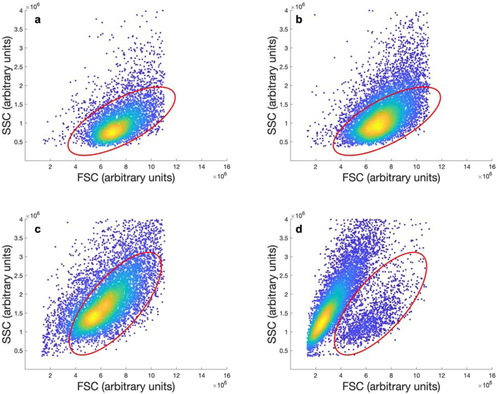
Sample gating of flow cytometry scatter plots for PEGDA 2000 coated cells without (a) and with (b) extrusion, and uncoated cells without (c) and with (d) extrusion. The gated regions indicate the position of cells that are intact.
3.1. Results and Discussion
The fabrication of functional tissue requires the rapid placement of specific cell types while preserving their integrity and function. Five formulations of cellular coatings were selected to systematically relate the relevant coating design parameters to the protection of the cell during rapid extrusion. These coated cells were then extruded through a capillary tube at higher rates than those typically used during extrusion printing to intentionally subject the cells to damaging shear stresses and depressurizations greater than those imposed on cells in modern bioprinters. The mode of cellular protection is then related to the coating material’s bulk properties. Cellular protection is evaluated in the context of a bioprinted heart. A heart is a vascular tissue that demands exceptional resolution of cell laden materials, and the size of a human heart will require an acceleration of print speed to handle the large volumes. This study focuses on H9C2 cells as a commonly used in vitro model [22, 23] for primary cardiomyocytes in bioprinting and multiple other applications [23–27]. Mature primary cardiomyocytes are not capable of expansion nor significant manipulation in vitro, and are poor candidate cells for inclusion in bioprinted tissues. Significant advancements are being made in cardiomyocytes derived from an induced pluripotent stem cell populations, but these cells are largely cost prohibitive at this stage. Although each cell type will have a unique sensitivity to the bioprinting environment, the analysis of coated H9C2 cells will provide general guidance on this commonly printed cell line.
3.1.1. Deposition of polymer coatings on the cell surface.
Polymer coatings were deposited onto the peripheral membrane of the H9C2 cells, as previously described for GelMA and PEGDA macromers [16, 28–33]. The presence of the polymer coating was verified by fluorescent labeling of the coating followed by the epifluorescent imaging of the coated cell. For coatings based on GelMA/PEGDA3350 blends, antibodies against collagen strongly label the gelatin content (Fig 3a). PEGDA coatings are visualized (Figure 3b–e) by physically entrapping fluorescent nanoparticles into the coating during polymerization [16, 28–33].
Figure 3:
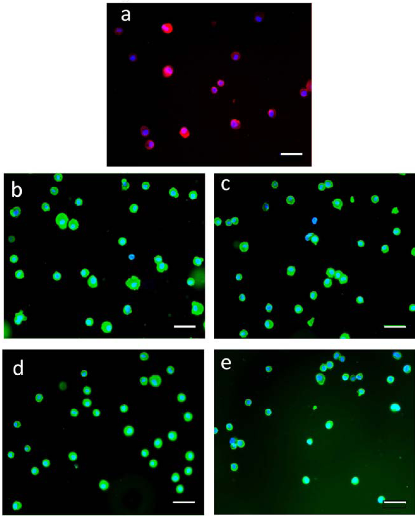
Fluorescence micrographs of H9C2 cells encapsulated with hydrogel coatings. The coatings containing GelMA are labeled with a primary antibody against collagen followed by a fluorescent secondary antibody (a). Coating of PEGDA macromers are copolymerized with 20 nm yellow-green nanoparticles for (b) PEGDA 700, (c) PEGDA 1000, (d) PEGDA 2000, (e) PEGDA 3350. All scale bars are 50 μm.
3.1.2. Viability of cells following rapid extrusion
Bioprinting was simulated by the extrusion of H9C2 cells through a narrow capillary tube. Experiments were conducted at conditions exceeding the experimental range supportive of high viability in order to study the limitations of high throughput, high resolution bioprinting. Cell samples were analyzed by flow cytometry both with and without the extrusion process to determine protection afforded by each polymer coating. Prior to extrusion, events were gated for intact cells. Identical gates were used for samples following extrusion through the capillary to denote fraction of cell events that remained intact after being subject to harsh shear forces. Following extrusion, the fraction of intact cell events was observed and normalized to the fraction of intact cells prior to extrusion. All cell samples were then analyzed by two additional viability assays: MTT proliferation assay, and ethidium homodimer permeation assay. Figure 4 is a compilation of all of the scattering and viability data for each polymer used with and without extrusion.
Figure 4:
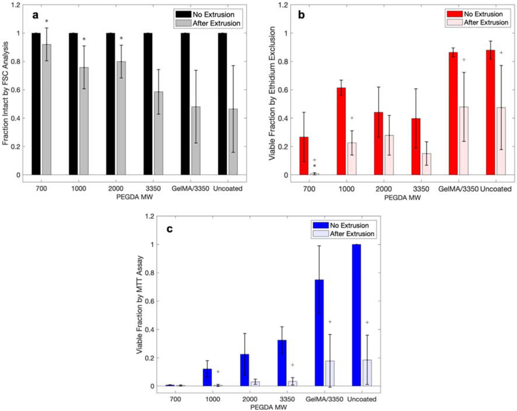
Cell viability for each assay type with and without extrusion for each polymer coating. a) Normalized FSC analysis with flow cytometry, b) ethidium permeability assay, and c) MTT proliferation assay. (Statistical analyses were conducted comparing samples of with/without extrusion, and after extrusion of coated to uncoated cells. * indicates statistically different means from the coated extrusion to the uncoated extrusion group. + indicates statistically different means of the same sample with and without extrusion.) Each point are mean values and error bar are standard deviations.
The polymerization of individual hydrogel coatings impacts the viability of the H9C2 cardiomyoblasts as analyzed by forward scatter and side scatter for cellular intactness (Figure 4a), by ethidium permeability assay (Figure 4b), and MTT proliferation assay (Figure 4c). There is a clear trend that the low molecular weight PEGDA macromers is correlated with a higher fraction of intact cells. It has been previously established that the molecular weight of PEGDA macromer is predictive of mechanical properties of the formed gel [34]. It has also been observed previously [35] that the molecular weight of the PEGDA macromer used is inversely related to the toxicity of the macromer. PEGDAs of molecular weight of less than 1000 are inherently toxic to H9C2 cardiomyoblasts, while the larger PEGDA 2000 and 3350 are much more cytocompatible. This is clearly observed in Figure 4b and c. The MTT proliferation assay shows increased cell activity with increased polymer molecular weight from PEGDA 700 to PEGDA 3350.
Some formulations of polymer coatings on cells protect the cells from these intensified bioprinting conditions. In particular, the number of cells that remain intact following extrusion is significantly increased (p < 0.05, Table S1) for PEGDAs 700, 1000, and 2000 when compared to the uncoated cells. The relative protection afforded by the protective polymer coatings, shows the presence of intact cells that are lacking viability.
3.1.2. Mechanical properties of bulk coating materials
Linear PEGDA over a range of molecular weights was utilized due the ability to incrementally vary mechanical properties using molecules of the same functional groups. Table 1 shows all of the mechanical properties for each of the polymers studied. Moduli ranged from 9.2 +/− 0.79 kPa for GelMA/3350 to 1269 +/− 103 kPa for PEGDA 1000. Although PEGDA 700 did not show the highest modulus, the average modulus of PEGDA 1000 and PEGDA 700 were not statistically different. This suggests that the small difference in molecular weight of these two macromers does not greatly affect the mechanical properties. Therefore, the expected trend of increasing modulus with decreasing macromer molecular weight is still preserved. This trend is due to the formation of a more tightly crosslinked network with the lower molecular weight PEGDAs. The ability of a gel to deform is dependent on multiple factors such as molecular weight, chain linearity, and functional group interactions. However, in this case the chemistry of the repeat units is constant (except for GelMA) across the different molecular weight macromers used. Therefore, the major factor in resistance to deformation is the density of the covalent crosslinks within the network. For the linear PEGDA macromers used here, this is directly dependent on the macromer molecular weight. As macromer molecular weight decreases, molecular weight between crosslinks decreases, increasing the density of covalent crosslinks within the gel and therefore increasing the observed stiffness.
Table 1:
All mechanical properties recorded for each polymer assessed. Data reported as mean ± standard deviation.
| Macromer | Swelling Ratio | Modulus (kPa) | Ultimate Tensile Strength (kPa) | Max Strain (%) |
|---|---|---|---|---|
| 700 | 3.02 ± 0.03 | 1.21 × 10³ ± 127 | 138 ± 36 | 11 ± 2.7 |
| 1000 | 3.77 ± 0.12 | 1.26 × 10³ ± 103 | 128 ± 26 | 9 ± 1.4 |
| 2000 | 5.41 ± 0.12 | 502 ± 61 | 134 ± 23 | 9 ± 3.6 |
| 3350 | 7.21 ± 0.01 | 204 ± 20 | 55.0 ± 7.1 | 25 ± 0.94 |
| GelMA/3350 | 15.4 ± 0.89 | 9.2 ± 0.79 | 6 × 10⁻⁴ ± 3 × 10⁻⁴ | 44 ± 13 |
The calculated swelling ratios of the five formulations ranged from 3.02 +/− 0.03 for PEGDA 700, to 15.41 +/− 0.89 for GelMA/3350. The observed swelling ratio decreases as the molecular weight of the macromer decreases. This is due to a decrease in molecular weight between covalent crosslinks within the hydrogel network, which limit the ability of the gel to take on water.
3.1.3. Relating coating mechanical properties to cell lysis
In conventional systems, the lysis of a cell is a manifestation of a mechanical failure of the cell’s peripheral membrane. This is easily observed in hypotonic media, where the cell swells and bursts. In the case of a polymer coated cell, cell lysis requires the failure of the unified cell membrane polymer coating structure. As such, the resistance to complete cell lysis is expected to be related to the stress at failure, which in the case of these gels is the Ultimate Tensile Stress (UTS) of the bulk polymer material. When the UTS of each coating material is plotted against the fraction of cells that remain intact following rapid capillary extrusion, a strong positive correlation is observed (Figure 5c). Polymers with UTS less than 100 kPa (GelMA/3350 and PEGDA 3350) do not show significant protection over uncoated cells. The shear forces experienced in the capillary tubes may be large enough to rupture the cell coating of the weaker gels, as depicted in Figure 1. Polymer coatings of the higher UTS and modulus gels (PEGDA’s 700, 1000, and 2000) showed a significantly higher protection from lysis due to shear forces than the softer gels (PEGDA 3350 and GelMA/3350). The observed UTS’s for the three polymers that show significant protection are not distinguishable between one another. However, all three show significantly higher (p < 0.05) UTS than PEGDA 3350 and GelMA/3350, which do not significantly protect from lysis compared to uncoated cells.
Figure 5:
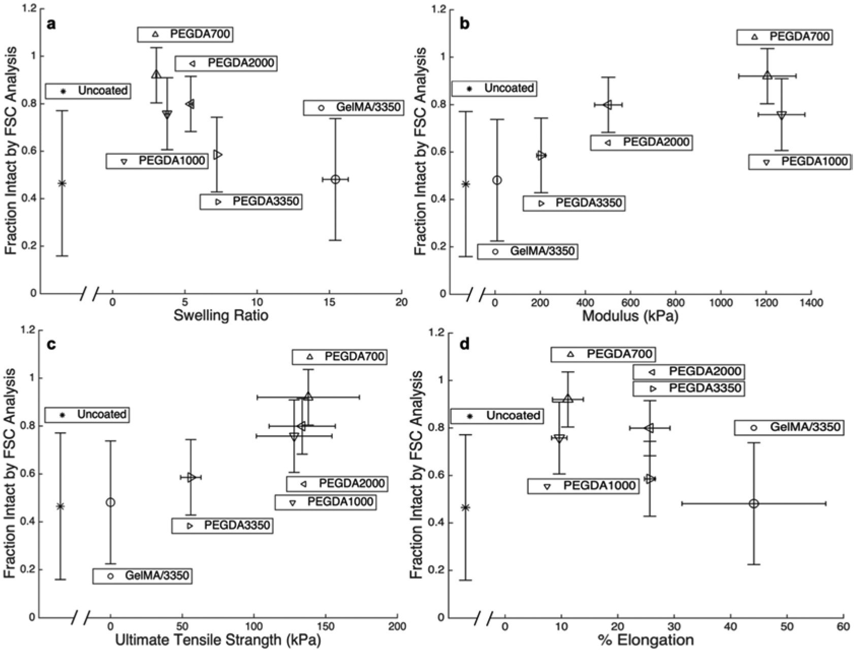
Fraction of cells remaining intact by FSC analysis following extrusion plotted against a) swelling ratio, b) modulus, c) UTS, and d) percent elongation at failure for each of the five macromers studied as well as uncoated cells. Each point are mean values and error bar are standard deviations.
3.1.4. Relating coating mechanical properties to membrane integrity and proliferative function
Viability data are plotted against all measured mechanical properties of each polymer to observe trends in protection. Figures 6 and 7 compare the physical properties of the bulk gels of the five different polymer coatings to viability by membrane permeability and proliferation, respectively. The viability of all extruded cells (coated and uncoated) being relatively low is desirable when bioprinting. With the exception of cells in PEGDA 700 which is known to be relatively toxic and permeabilizes the cell membrane, the viability of coated cells is similar to that of uncoated cells (Figure 4b and b). Although the gels possessing the higher UTS’s protect cells from complete lysis (Figure 5c), damage to the peripheral cell membrane occurs for under all condition tested (Figures 6). This indicates that the hydrogel coatings still allow enough deformation to induce damage to the cellular membrane. Likewise, Figure 7 illustrates that even though the cells are intact with the protective coatings (PEGDA 700, 1000, and 2000) the intact cells do not maintain a high level of normal cellular function for any polymer system studied. While reduced cellular function may partially be due to macromer toxicity, it may also be partially due to the mechanical stresses experienced by the cells within the hydrogel coating at a level beyond that which lead to impairment cell functionality without completely lysing the cell. This results in preservation of the cell’s forward and side scatter profile, without preservation of cell viability and function.
Figure 6:
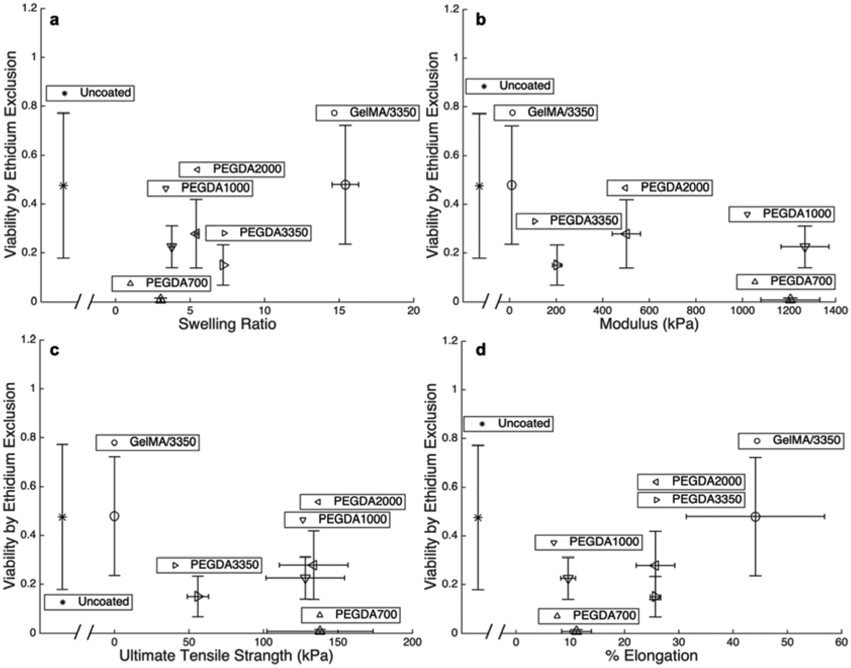
Fraction of cells with full membrane integrity determined by ethidium exclusion plotted against a) swelling ratio, b) modulus, c) UTS, and d) percent elongation at failure for each of the five macromers studied as well as uncoated cells following extrusion. Each point are mean values and error bar are standard deviations.
Figure 7:
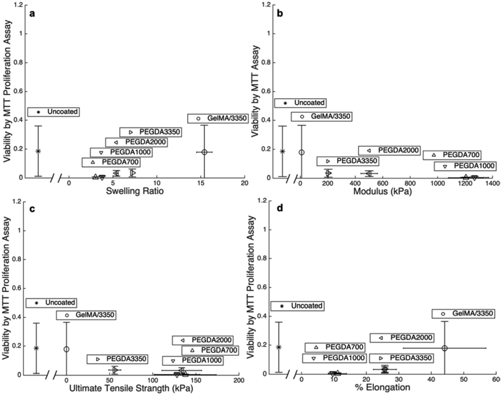
Fraction of functional cells following extrusion determined by MTT proliferation assay plotted against a) swelling ratio, b) modulus, c) UTS, and d) percent elongation at failure for each of the five macromers studied as well as uncoated cells. Each point are mean values and error bar are standard deviations.
The trend in lysis protection by FSC analysis (Figure 5) of each polymer is contrasted with that of the toxicity of the polymerization scheme. Although PEGDAs 700, 1000, and 2000 shows significant protection against lysis, the molecular weight is low enough to cause significant cell toxicity during polymerization. When the polymerization damage is paired with the mechanical stresses imposed during cellular extrusions, the cell membrane integrity and proliferation are compromised. The PEGDA 3350 and the GelMA/3350 formulations show an increase in all viability metrics immediately following polymerization compared to PEGDA 2000 and below (Figure 4B, C). Cells encapsulated by coatings derived from these same PEGDA 3350 and the GelMA/3350 formulations, however, show a significant decrease in viability during extrusion. While these two formulations are much less toxic to cells, they do not offer sufficient mechanical reinforcement to protect cells during extrusion.
The lack of protection afforded to cells encapsulated with PEGDA 3350 undergoing shear is in direct contrast to the mechanical protection cells encapsulated with these same coatings receive against hypotonic stresses [16]. As a result, it is concluded that the damage is different for hypotonic lysis and extrusion lysis. The cell in hypotonic lysis is expanded by osmotic pressure and the added stiffness of the coating under biaxial tension resists the rupture of the cell membrane and preserves intracellular function. In these high-speed extrusion systems, the mechanism of cellular damage needs further clarification.
3.1.5. Decoupling shear induced cell damage from pressure effects
In pneumatically or mechanically driven extrusion systems, cells experience very abrupt (i.e., step function-type) changes in pressure (~16 bar in < 0.1 s) and high shear stress. As the cell-laden solution is printed, the pressure rapidly decreases to atmospheric pressure which may disrupt the cell membrane or cell organelles [18]. During extrusion, the pressure drop that drives fluid flow through the bioprinter outlet port is coupled to the shear stress in the flow field. As a result, pressure and shear stress cannot be independently varied within an extrusion flow system in order to evaluate the relative contributions of each to cell damage. In the present study, pressure-associated cellular damage was decoupled from and shear associated cellular damage by using two separate systems.
The potential for high pressure and rapid depressurization to damage cells was evaluated independent of fluid flow-derived shear. Cells were pressurized to 25 bar with nitrogen in a pressure chamber, and then rapidly depressurized in <1 s to bring the cell solution back to atmospheric pressure. This magnitude of pressure and rate of depressurization are similar to those seen in this aggressive extrusion system, where the cells experience changes in pressure from ~16 bar to atmospheric pressure in <1 s as they pass through the capillary tube. The pressure changes alone did not affect cell viability and cell functionality metrics (Figure 8). There were no difference in viability or proliferation rates for cells maintained under atmospheric pressure or those experiencing pressures up to 25 bar and for up to 10 min. Thus, the pressurization cycle used in our mock bioprinting set up did not damage cells. It should be noted that cells have been reported to experience pressure damage, including cell lysis, but after exposure to the higher pressures and longer durations, for example during cavitation in other settings [17, 18]. High cell viability and function following rapid depressurization supports the hypothesis that the cell damage upon extrusion printing is largely shear mediated. This phenomenon is widely proposed in literature [36–38], but had not been studied independently for confirmation.
Figure 8:
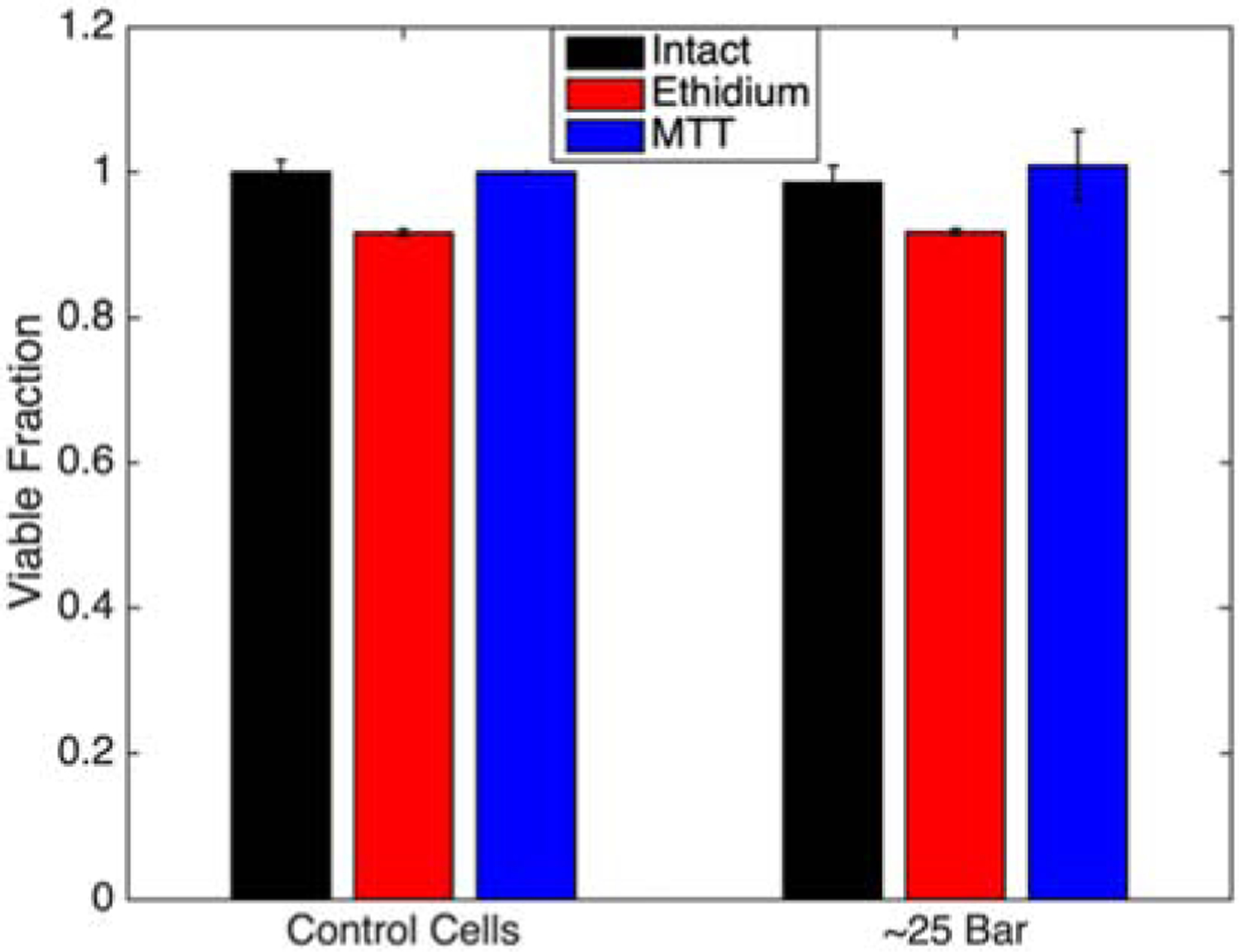
Cell viability for each assay type following exposure to high pressures (~25 bar) and rapid decompression (< 0.1s) back to atmospheric conditions. Bars are mean ± standard deviation
To conclusively link shear stress and not pressure to the cellular damage observed in rapid extrusion, cells were sheared in the absence of pressure variation. Coated or uncoated cells were subject to large shear forces using parallel disc system on a DHR-2 Viscometer (TA Instruments). The parallel disc was assembly run at a maximum speed to generate a wall shear stress of ~110 Pa, and then analyzed as before for complete lysis, membrane integrity, and proliferative function. Although the wall shear stress is lower than that of the extrusion system (~400 Pa), similar levels of each type of damage to uncoated control cells populations was observed consistent with our previous observation that shear is the predominant mechanism for cell damage [1–3]. Polymer coated cells resist lysis by shear in a similar manner as in a shear-pressure coupled extrusion system (Figures 4a and 9). The similar trend of cell membrane damage and reduction in proliferative capacity in the shear-only system compared that of the extrusion system supports the notion of shear forces play a dominant role in cell damage upon extrusion.
Figure 9:
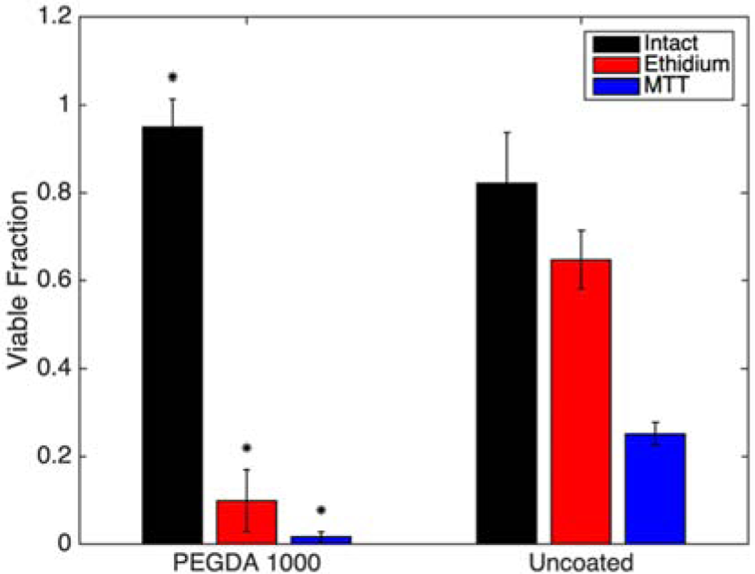
Cell viability for each assay type following exposure to shear forces in the absence of pressure changes. (* indicates statistically different means from the corresponding uncoated group.) Bars are mean ± standard deviation
4.1. Conclusions
Here, polymer coatings were used to evaluate the mechanism of cell protection in 3D bioprinting. Polymers containing a range of different properties were used to individually-encapsulate cells prior to exposure to high shear forces associated with high throughput, high resolution bioprinting. Shear mediated damage due to mechanical forces imposed on cells during extrusion through a bioprinter appears impact cell viability while the sudden depressurization cells experience during extrusion have negligible effects. The encapsulation of cells in a protective hydrogel coating protects the cells from complete lysis, but may still not protect it from deformation that is within the elastic limit of the hydrogel but surpasses that of the cellular membrane. The design of submicron coatings to protect against lysis of the peripheral membrane under these shear conditions is restricted to an ultimate tensile strength greater than 100 kPa. Critically, in this parameter space, the coating precursors capable of delivering these lysis-protective mechanical properties were inherently cytotoxic and caused substantial damage to the cell from the coating process alone. However, the chosen materials allowed for small changes in hydrogel properties highlighting desired limits such as a UTS of greater than 100 kPa. Together, these analyses conclude that the coatings that protect cells against hypotonic lysis are not protective against all modes of cell death observed during high speed printing. Finally, the possible damaging effects of a rapid depressurization were decoupled from those of the high shear in bioprinting. Using this analysis, only shear is conclusively correlated with cellular damage. As such, future efforts focusing on shear protection of single cells in high speed, high resolution printing are justified over those considering pressure effects.
Supplementary Material
Acknowledgements:
This work was partially supported by the National Institutes of Health (grant number R01 HL127682-04) and the National Science Foundation (CBET-1351531, CBET-1758210, OIA-1849213). We appreciate the help of Aaron Snell of Dr. Chris Richards’ lab for use of the pressure chamber, the help of Felix Akharume of Dr. Akinbode Adedeji’s lab with the use of the viscometer, and the help of Justin Glover with the custom-built tensile tester. We are appreciative of the support of Dr. Joseph Halcomb III for providing the Halcomb Fellowship in Medicine and Engineering to CFC.
Footnotes
Publisher's Disclaimer: This is a PDF file of an unedited manuscript that has been accepted for publication. As a service to our customers we are providing this early version of the manuscript. The manuscript will undergo copyediting, typesetting, and review of the resulting proof before it is published in its final form. Please note that during the production process errors may be discovered which could affect the content, and all legal disclaimers that apply to the journal pertain.
Publisher's Disclaimer: The findings and conclusions in this paper have not been formally disseminated by the Food and Drug Administration and should not be construed to represent any agency determination or policy. The mention of commercial products, their sources, or their use in connection with material reported herein is not to be construed as either an actual or implied endorsement of such products by Department of Health and Human Services.
References:
- 1.Chang R, Nam J, and Sun W, Direct cell writing of 3D microorgan for in vitro pharmacokinetic model. Tissue Engineering Part C: Methods, 2008. 14(2): p. 157–166. [DOI] [PubMed] [Google Scholar]
- 2.Blaeser A, et al. , Controlling shear stress in 3D bioprinting is a key factor to balance printing resolution and stem cell integrity. Advanced healthcare materials, 2016. 5(3): p. 326–333. [DOI] [PubMed] [Google Scholar]
- 3.Nair K, et al. , Characterization of cell viability during bioprinting processes. Biotechnology Journal: Healthcare Nutrition Technology, 2009. 4(8): p. 1168–1177. [DOI] [PubMed] [Google Scholar]
- 4.Maul TM, et al. , Mechanical stimuli differentially control stem cell behavior: morphology, proliferation, and differentiation. Biomechanics and modeling in mechanobiology, 2011. 10(6): p. 939–953. [DOI] [PMC free article] [PubMed] [Google Scholar]
- 5.KHATIWALA C, et al. , 3D cell bioprinting for regenerative medicine research and therapies. Gene Therapy and Regulation, 2012. 7(01): p. 1230004. [Google Scholar]
- 6.Murphy SV and Atala A, 3D bioprinting of tissues and organs. Nature biotechnology, 2014. 32(8): p. 773. [DOI] [PubMed] [Google Scholar]
- 7.Mandrycky C, et al. , 3D bioprinting for engineering complex tissues. Biotechnology advances, 2016. 34(4): p. 422–434. [DOI] [PMC free article] [PubMed] [Google Scholar]
- 8.Billiet T, et al. , The 3D printing of gelatin methacrylamide cell-laden tissue-engineered constructs with high cell viability. Biomaterials, 2014. 35(1): p. 49–62. [DOI] [PubMed] [Google Scholar]
- 9.Zhao Y, et al. , Three-dimensional printing of Hela cells for cervical tumor model in vitro. Biofabrication, 2014. 6(3): p. 035001. [DOI] [PubMed] [Google Scholar]
- 10.Chung JH, et al. , Bio-ink properties and printability for extrusion printing living cells. Biomaterials Science, 2013. 1(7): p. 763–773. [DOI] [PubMed] [Google Scholar]
- 11.Zhu K, et al. , Gold nanocomposite bioink for printing 3D cardiac constructs. Advanced functional materials, 2017. 27(12): p. 1605352. [DOI] [PMC free article] [PubMed] [Google Scholar]
- 12.Qi H, et al. , In vitro spatially organizing the differentiation in individual multicellular stem cell aggregates. Critical reviews in biotechnology, 2016. 36(1): p. 20–31. [DOI] [PubMed] [Google Scholar]
- 13.Zhang W, et al. , Advances in experimental approaches for investigating cell aggregate mechanics. Acta Mechanica Solida Sinica, 2012. 25(5): p. 473–482. [Google Scholar]
- 14.Marga F, et al. , Toward engineering functional organ modules by additive manufacturing. Biofabrication, 2012. 4(2): p. 022001. [DOI] [PubMed] [Google Scholar]
- 15.Jakab K, et al. , Engineering biological structures of prescribed shape using self-assembling multicellular systems. Proceedings of the National Academy of Sciences, 2004. 101(9): p. 2864–2869. [DOI] [PMC free article] [PubMed] [Google Scholar]
- 16.Romero G, et al. , Protective Polymer Coatings for High-Throughput, High-Purity Cellular Isolation. ACS Applied Materials & Interfaces, 2015. 7(32): p. 17598–17602. [DOI] [PMC free article] [PubMed] [Google Scholar]
- 17.Moonschi FH, et al. , Cell-Derived Vesicles for Single-Molecule Imaging of Membrane Proteins. Angewandte Chemie, 2015. 127(2): p. 491–494. [DOI] [PubMed] [Google Scholar]
- 18.Moonschi FH, et al. , Mammalian Cell-derived Vesicles for the Isolation of Organelle Specific Transmembrane Proteins to Conduct Single Molecule Studies. The Journal of Biological Chemistry, 2017. [DOI] [PMC free article] [PubMed] [Google Scholar]
- 19.Hansen RR, Sikes HD, and Bowman CN, Visual detection of labeled oligonucleotides using visible-light-polymerization-based amplification. Biomacromolecules, 2007. 9(1): p. 355–362. [DOI] [PubMed] [Google Scholar]
- 20.Pham JT, et al. , Spontaneous jumping, bouncing and trampolining of hydrogel drops on a heated plate. Nature communications, 2017. 8(1): p. 905. [DOI] [PMC free article] [PubMed] [Google Scholar]
- 21.Sun TL, et al. , Bulk Energy Dissipation Mechanism for the Fracture of Tough and Self-Healing Hydrogels. Macromolecules, 2017. 50(7): p. 2923–2931. [Google Scholar]
- 22.Zordoky BN and El-Kadi AO, H9c2 cell line is a valuable in vitro model to study the drug metabolizing enzymes in the heart. Journal of pharmacological and toxicological methods, 2007. 56(3): p. 317–322. [DOI] [PubMed] [Google Scholar]
- 23.Watkins SJ, Borthwick GM, and Arthur HM, The H9C2 cell line and primary neonatal cardiomyocyte cells show similar hypertrophic responses in vitro. In Vitro Cellular & Developmental Biology-Animal, 2011. 47(2): p. 125–131. [DOI] [PubMed] [Google Scholar]
- 24.Ho CMB, et al. , 3D printed polycaprolactone carbon nanotube composite scaffolds for cardiac tissue engineering. Macromolecular bioscience, 2017. 17(4): p. 1600250. [DOI] [PubMed] [Google Scholar]
- 25.Yin Y, et al. , Cardioprotective effect of Danshensu against myocardial ischemia/reperfusion injury and inhibits apoptosis of H9c2 cardiomyocytes via Akt and ERK1/2 phosphorylation. European journal of pharmacology, 2013. 699(1–3): p. 219–226. [DOI] [PubMed] [Google Scholar]
- 26.Bernuzzi F, et al. , Reactive oxygen species-independent apoptosis in doxorubicin-treated H9c2 cardiomyocytes: role for heme oxygenase-1 down-modulation. Chemico-biological interactions, 2009. 177(1): p. 12–20. [DOI] [PubMed] [Google Scholar]
- 27.Jastrzebska E, Tomecka E, and Jesion I, Heart-on-a-chip based on stem cell biology. Biosensors and Bioelectronics, 2016. 75: p. 67–81. [DOI] [PubMed] [Google Scholar]
- 28.Avens HJ, et al. , Sensitive Immunofluorescent Staining of Cells via Generation of Fluorescent Nanoscale Polymer Films in Response to Biorecognition. Journal of Histochemistry & Cytochemistry, 2011. 59(1): p. 76–87. [DOI] [PMC free article] [PubMed] [Google Scholar]
- 29.Avens HJ, et al. , Fluorescent polymeric nanocomposite films generated by surface-mediated photoinitiation of polymerization. Journal of Nanoparticle Research, 2011. 13(1): p. 331–346. [Google Scholar]
- 30.Wu P-J, et al. , Hydrogel Patches on Live Cells through Surface-Mediated Polymerization. Langmuir, 2017. 33(27): p. 6778–6784. [DOI] [PMC free article] [PubMed] [Google Scholar]
- 31.Lilly JL, et al. , Characterization of molecular transport in ultrathin hydrogel coatings for cellular immunoprotection. Biomacromolecules, 2015. 16(2): p. 541–549. [DOI] [PMC free article] [PubMed] [Google Scholar]
- 32.Lilly JL, et al. , Comparison of eosin and fluorescein conjugates for the photoinitiation of cell-compatible polymer coatings. PloS one, 2018. 13(1): p. e0190880. [DOI] [PMC free article] [PubMed] [Google Scholar]
- 33.Lilly JL and Berron BJ, The Role of Surface Receptor Density in Surface-Initiated Polymerizations for Cancer Cell Isolation. Langmuir, 2016. 32(22): p. 5681–5689. [DOI] [PMC free article] [PubMed] [Google Scholar]
- 34.Browning M, et al. , Compositional control of poly (ethylene glycol) hydrogel modulus independent of mesh size. Journal of Biomedical Materials Research Part A, 2011. 98(2): p. 268–273. [DOI] [PubMed] [Google Scholar]
- 35.Liu G, et al. , Cytotoxicity study of polyethylene glycol derivatives. RSC Advances, 2017. 7(30): p. 18252–18259. [Google Scholar]
- 36.Augenstein D, Sinskey A, and Wang D, Effect of shear on the death of two strains of mammalian tissue cells. Biotechnology and bioengineering, 1971. 13(3): p. 409–418. [DOI] [PubMed] [Google Scholar]
- 37.Kong HJ, Smith MK, and Mooney DJ, Designing alginate hydrogels to maintain viability of immobilized cells. Biomaterials, 2003. 24(22): p. 4023–4029. [DOI] [PubMed] [Google Scholar]
- 38.Colosi C, et al. , Microfluidic bioprinting of heterogeneous 3D tissue constructs using low-viscosity bioink. Advanced Materials, 2016. 28(4): p. 677–684. [DOI] [PMC free article] [PubMed] [Google Scholar]
Associated Data
This section collects any data citations, data availability statements, or supplementary materials included in this article.


