Abstract
Minimally invasive therapies avoiding surgical complexities evoke great interest in developing injectable biomedical devices. Herein, we report a versatile approach for engineering injectable and biomimetic nanofiber microspheres (NMs) with tunable sizes, predesigned structures, and desired compositions via gas bubble-mediated co-axial electrospraying. The sizes and structures of NMs were controlled by adjusting processing parameters including air flow rate, applied voltage, distance, and spinneret configuration in the co-axial setup. Importantly, unlike the self-assembly method, this technique can be used to fabricate NMs from any material feasible for electrospinning or other nanofiber fabrication techniques. To demonstrate the versatility, we successfully fabricated open porous NMs consisting of various short nanofibers made of poly(ε-caprolactone), poly(lactic-co-glycolic acid), gelatin, methacrylated gelatin, bioglass, and magneto-responsive polymer composites. Open porous NMs supported human neural progenitor cell growth in 3D with larger number and more neurites than nonporous NMs. Additionally, highly open porous NMs showed faster cell infiltration and host tissue integration than nonporous NMs after subcutaneous injection to rats. Such a novel class of NMs holds great potential for many biomedical applications such as tissue filling, cell and drug delivery, and minimally invasive tissue regeneration.
Keywords: Co-axial Electrospray, Nanofiber Microspheres, Gas Bubbles, Cell Delivery, Tissue Regeneration
Graphical
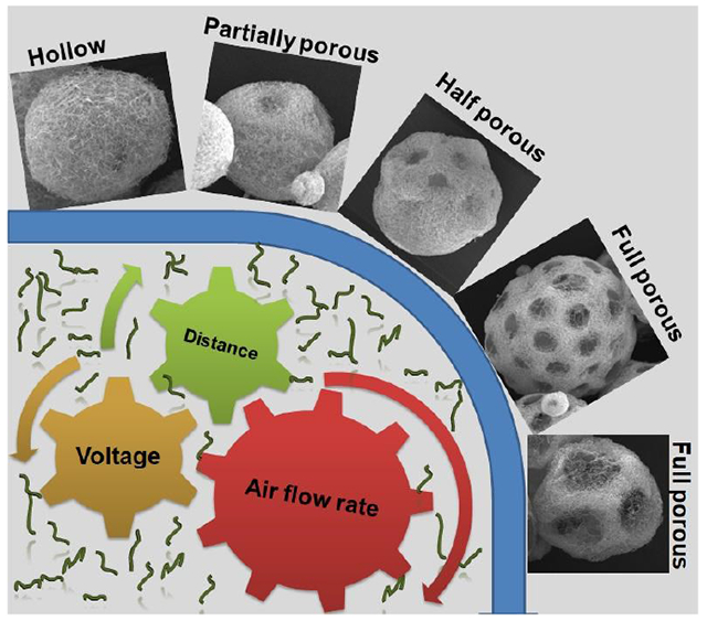
An approach is reported for engineering injectable and biomimetic nanofiber microspheres (NMs) with tunable sizes, predesigned structures, and desired compositions via gas bubble-mediated co-axial electrospraying. Highly open porous NMs showed faster cell infiltration and host tissue integration than nonporous NMs after subcutaneous injection to rats. Such a novel class of NMs holds great potential for many biomedical applications.
Injectable biomaterials represent a new wave of minimally invasive therapeutics to complement the release of drugs, delivery of biologics, and integration of cells at specific sites of injury [1–3]. Unlike implantable scaffolds, injectable biomaterials can fill irregularly shaped tissue defects without requiring surgical implantation. Hence, there has been increasing interest in the development of new injectable biomaterials. Among them, nanofiber microspheres (NMs) have emerged as superior cell and therapeutic carriers due to their unique properties like injectability and biomimetic microarchitectures [4–7]. To date, several different synthetic and natural polymeric materials (e.g., star-shaped poly (l-lactic acid) (PLLA), chitosan, chitin, cellulose, and collagen) have been fabricated into NMs based mainly on self-assembly (e.g., thermally-induced phase separation) [7–11]. The molecular structure plays a critical role in the NMs formation. For example, star-shaped PLLA-derived NMs morphologies were strictly determined by the arm length, arm number, and OH/LLA ratio [4, 6, 11]. In order to obtain the desired microstructures in the self-assembly process, all parameters must be precisely controlled during the polymer synthesis, thus fabrication of NMs is more difficult. Additionally, the solubility of natural polymers like chitosan, chitin, and cellulose is poor in organic solvents, which often demand the high temperatures to facilitate their dissolution in the self-assembly techniques. Therefore, this process fails to control the uniformity of pore size and pore distribution inside the NMs [9, 12].
Due to the ease of mass-production of uniform particles, electrospraying has been widely used to generate various microparticulate materials over the past two decades [13–15]. Recently, we unified the electrospraying with electrospinning techniques, where electrospun poly(ε-caprolactone) (PCL)/gelatin short nanofibers were electrosprayed into liquid nitrogen and crosslinked to form nonporous NMs for cell delivery [16]. Subsequently, we functionalized the nonporous NMs by tethering BMP-2-OCTAL and QK-OCTAL peptides, which facilitated osteogenesis of stem cells and vessel tube formation by endothelial cells in vitro, respectively [17]. Given the nature of nonporous NMs, the cell attachment, proliferation, differentiation, and organization was limited to the surface. Nonporous NMs may be a viable option for delivering and modulating a small volume of cells to a specific site of injury, however, porous NMs can support a higher volume of cells and enhance proliferation by supplying oxygen and nutrients through open pores [18–19]. More importantly, controlling the size and density of pores and subsequent rate of host cell infiltration in NMs enables them to be tuned for regeneration of specific types of tissues. Ideally, injectable NMs with interconnected pores increased cell loading, enhanced integration, and protected the seeded cells under shear stress [4, 18, 19]. Therefore, open porous NMs could facilitate microtissue formation in specific defect areas.
As one of the most common pore-inducing methods, gas-foaming is widely used and well understood [20–22]. Thus, we hypothesized that introducing air bubbles into the short nanofiber-containing microdroplets during co-axial electrospraying could enable the controlled creation of pores in NMs. To test our hypothesis, we used an innovative co-axial electrospraying technique to inject air bubbles into the microdroplets containing nanofiber segments as illustrated in Figure 1. We first fabricated PCL/gelatin (1:1) short nanofiber solutions (20 mg/mL) (containing 5% gelatin relative to the weight of short nanofibers) as previously reported [17]. The 50% gelatin content enhanced the hydrophilicity of the short nanofiber, which played a critical role to prepare well homogenized short nanofiber suspension. Moreover, the addition of binder/surfactant like gelatin during the ultrasound homogenization would enhance the stability of the suspension (Figure S1). In our previous study, we examined the effect of different fiber concentrations including 20 mg/mL and 15 mg/mL on the fabrication of non-porous NMs. The 20 mg/mL nanofiber solution in the presence of 0.5% of gelatin resulted in stable spherical NMs and the resultant microspheres were suitable for a long-term cell culture. Therefore, in this study we chose 20 mg/mL short nanofiber concentration for the fabrication of porous NMs Then, the homogenized was pumped through a shell needle while air was pumped through a core needle at preset flow rates. Droplets containing nanofiber segments formed at the tip of the shell needle, with air bubbles releasing from the core needle into the short nanofiber-containing droplets. Generated microdroplets were collected using a grounded collector containing liquid N2. After freezing on impact, the NMs were freeze-dried and crosslinked with glutaraldehyde (GA) vapor. As shown in Video S1 and S2, crosslinking played a critical role in maintaining the morphology of the NMs both in solution and under shear stress. In the absence of crosslinking, short fiber-composed porous NMs easily disassembled in water with gentle shaking (Video S1). However, amine-aldehyde covalent bonding between the gelatin (binder) and aldehyde through the GA-induced crosslinking formed mechanically stable NMs which were able to withstand vigorous shaking and shear stress during injection (Video S2). Though several types of NMs were previously reported, we presented for the first time a novel class of NMs with tunable structures and compositions capable of serving as injectable fillers for tissue defects and carrier for drug/cell/microtissue delivery and simultaneously regulating cell behavior and/or responding to external environments.
Figure 1. Schematic illustrating the fabrication of NMs using co-axial electrospray and their potential applications.
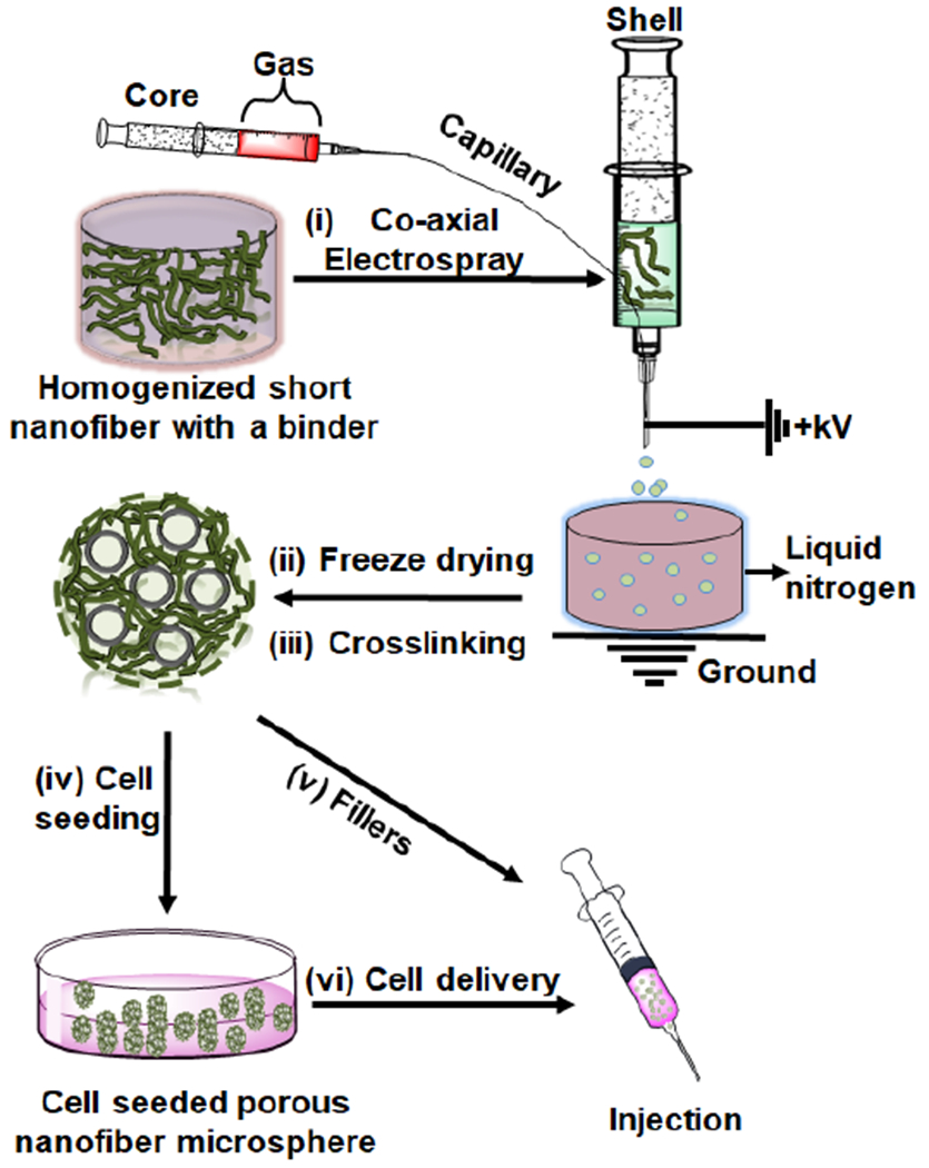
(i) Co-axial electrospraying a nanofiber segment-containing solution in the shell and air in the core. (ii) Freeze-drying NMs. (iii) Crosslinking NMs. (iv) Seeding cells to porous NMs. (v) Using as a filler to the tissue defect. (vi) Using as a carrier for cell delivery.
Given the dynamic nature of co-axial electrospraying, we examined a variety of parameters. First, we investigated the effect of airflow rates on the formation of NMs. Figure 2 shows SEM images of various PCL/gelatin NMs at airflow rates ranging from 1 to 10 mL/h. When applying the airflow rate at 1 mL/h, hollow NMs were obtained (Figure 2a,a1,a2). After increasing the airflow rate to 2 mL/h and 5 mL/h, the hollow NMs became partially porous (Figure 2b,b1,b2 and Figure 2c,c1,c2). After further increasing the airflow rate to 10 mL/h, completely open porous NMs were achieved (Figure 2d,d1,d2). The difference in morphologies could be due to the number of gas bubbles introduced within the droplets. At low airflow rates, bubbles were able to fuse and form a large bubble in the droplets with a pressure too low to break the nanofiber shell before freezing in the liquid N2. Figure 2a2 shows an SEM image of the cross-section of hollow NMs, indicating a thick nanofiber wall at 1 mL/h. The wall thickness reduced with increasing the airflow rate to 2 mL/h. However, further increasing the airflow rate to 5 mL/h and 10 mL/h caused an increase of the number of bubbles in each droplet. Eventually, some bubbles started to burst through the outer shell of nanofiber-containing droplets before dripping into the liquid N2, resulting in partially open porous (5 mL/h) and completely open porous architecture (10 mL/h). Figure 2e–f shows the quantitative measurements of pore size, microsphere diameter, and number of pores/microsphere as a function of airflow rate. Diameter (500 ± 50 μm) of collected NMs was independent of airflow rates, because electrical field and solution flow rate are the key factors to influence the size of the resultant particles and the electrical field and the solution flow rate in this set of experiments were constant. As the airflow rate increased from 5 to 10 mL/h, the number of pores on each microsphere increased from 10 to 30 and the pore size increased from 80 to 140 μm.
Figure 2. The effect of air flow rates on the formation of PCL:gelatin (1:1) NMs.
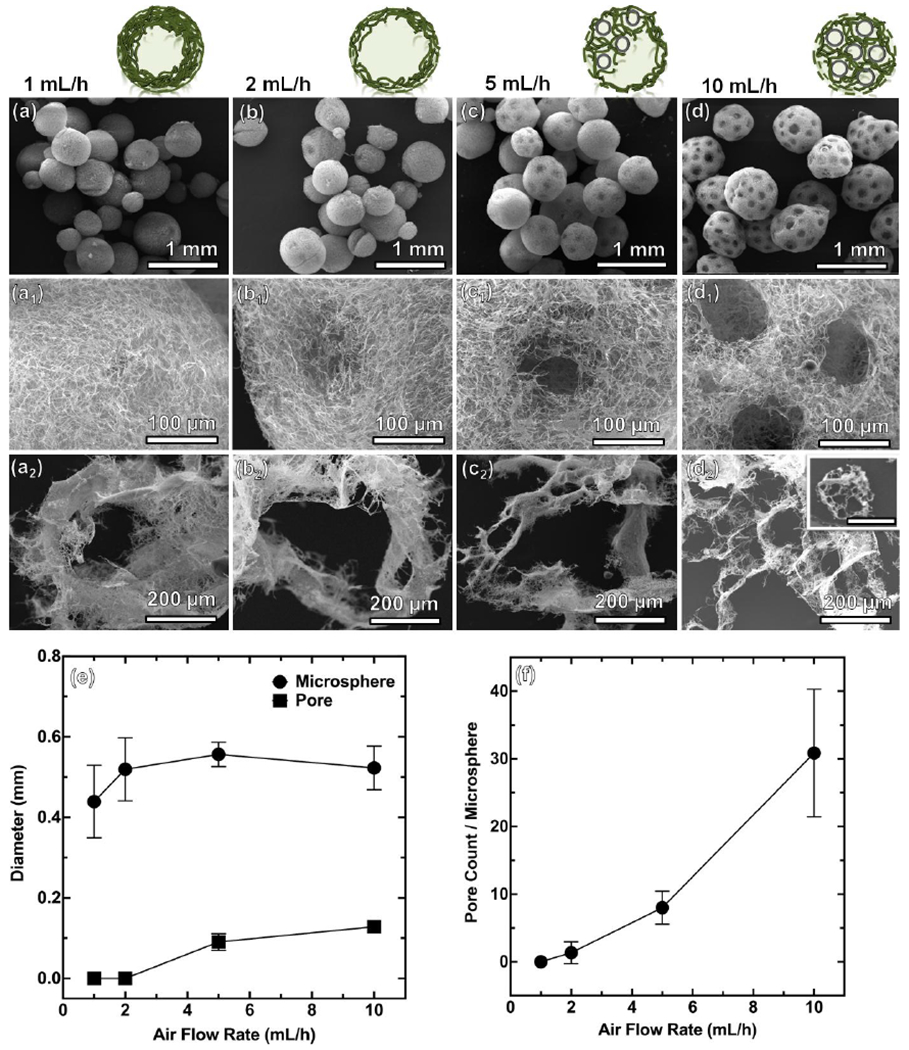
(a-a2) 1 mL/h. (b-b2) 2 mL/h. (c-c2) 5 mL/h. (d-d2) 10 mL/h. The other processing parameters: short nanofiber concentration = 20 mg/mL, solution flow rate =2 mL/h, applied voltage = 6 kV, distance between nozzle and collector = 10 cm. Scale bar in the inset of d2 = 500 μm. (e, f) Pore diameter and microsphere diameter and pore count/microsphere at different air flow rates.
To further analyze the mechanism by which NMs form, we proposed a model to understand how processing parameters dictate NM morphology (Figure S2a). In our model, which is loosely based on Cheng’s report [23], the short nanofiber-containing microdroplet solution is simply considered as a homogenous liquid. Additionally, we consider free bubbles (having departed from needle tip) and contacting bubbles (free bubbles in contact), both of which experience different forces [23]. The first relevant force that is not considered in our model but merits thought is force needed to overcome surface tension at the tip of the needle. Fst~σL, where σ is the surface tension of the film. Sufficient airflow forces, Faf ~ ρafu2A, are needed to overcome surface tension to generate a free bubble. At lower airflow rates, larger and less stable bubbles are formed. At higher airflow rates, many smaller, stable bubbles are formed. For a free bubble, though, the pressure caused by airflow from the core needle (Faf), buoyant force (FB), drag force imparted by the viscosity of the nanofiber solution (FD), and gravitational force (Fg) create a force-balance that dictates the movement and distribution of bubbles. The internal (FPin) pressure sustained by the bubble’s surface tension and internal gases are at an equilibrium with the external pressure (FPout) exerted by the nanofiber solution. Assuming a bubble in the solution has no change in size and a stable film, FPin = FPout, and the only forces acting on the bubble can be balanced as: FD + FB = Fg + Faf (Figure S2b). Here, gravitational forces and drag forces are miniscule and can thus be considered zero. The relevant forces after separation from the needle tip dictating the distribution of a single bubble are airflow and buoyancy (FB ~ ρfgVbubble). After separation from the needle and under low airflow rates, the buoyant force always causes the bubbles to rise, stopping only upon contact with the surface of the droplet or other bubbles. However, under higher airflow rates, the force of the airflow overcomes buoyant forces, resulting in a mixing effect that effectively distributes bubbles in solution.
As mentioned, at lower airflow rates, bubbles adhere to the core needle longer because the airflow force does not overcome the bubble tension to the needle, thus forming larger bubbles. As airflow increases, the size and number of bubbles also increase. At medium airflow rates, several medium-sized bubbles may form. Noting that bubbles with larger surface areas are unstable [24], several medium-sized bubbles will likely contact and fuse, forming larger bubbles and giving rise to hollow or half-hollow morphologies. At significantly higher airflow rates, many smaller bubbles are produced due to increases in airflow-imparted forces and a constant perturbation of the film along the needle tip. These small bubbles are more stable and do not succumb to fusion [25]. Following the Laplace-Young equation, when a bubble with smaller pressure (larger radius) contacts a neighboring bubble, a film forms between them and bends toward the bubble with the smallest pressure, attempting to minimize surface area [26]. This phenomenon explains the formation of interconnected pores that retain distinct morphologies. An overall force-balance equation can be used to understand how contacting bubbles move and form porous channels in bubble-infused solutions. Considering two contacting bubbles in a static model, here, all bubbles experience an internal pressure (FPin), external pressure exerted by the surrounding nanofiber solution (FPout), buoyant forces (FB), drag forces opposite to moving direction (FD), gravitational forces (Fg), and forces from the airflow leaving the core needle (Faf) (Figure S2c). However, bubbles in contact impart new forces to one another – namely attractive forces due to surface tension along contact films (FT) and repulsive forces (Frep) from Van der Waal forces. Again, forces from gravity and drag may be considered negligible, but Van der Waalforces become significant. As separation distance between two bubbles of like charges decrease, Van der Waal forces increase, resulting in an electrostatic repulsion between the two bubbles. The distribution of bubble clusters is controlled mainly by airflow rate, Van der Waal repulsion, and buoyancy. The mechanics can be loosely summarized as forces in the X and Y axis in planar model where ΣFy = Fg + sinθ × Faf − FB − FD and ΣFx = FT + cosθ × Faf − Frep. It is worth noting that in the given force equations, the internal and external pressures are assumed to be zero as they do not contribute to bubble movement in solution when the bubble size is unchanged. Under these given assumptions, it becomes obvious that the delicate interplay between airflow forces, buoyancy, and Van der Waal repulsion between like bubbles largely dictate the porous structure of NMs. Manipulating the airflow rate of the core needles changes the forces countering buoyancy, the number of bubbles, and indirectly determines the amount of Van der Waal repulsion.
After establishing a working relationship between the structures of NMs relative to airflow rates, we then investigated the influence of applied voltages. The applied voltages during co-axial electrospray were varied from 0 to 15 kV. At 0 kV, the air bubbles floated to the upper half of the droplet due to buoyant forces (Figure S3a and Video S3). At 0 kV and airflow rate of 10 mL/h, dripping into the liquid N2 occurred mainly due to gravity and the force imparted by airflow. Droplet mass increased until the sum of gravitational force and the force imparted by airflow overcame the surface tension between the needle and the microdroplet. Figure 3a,a1 shows the SEM images of the collected NMs at 0 kV, suggesting half of the microspheres is porous, which was consistent with the photograph in Figure S3a. At low applied voltages of 1 and 3 kV, the size of NMs decreased while their surfaces showed a Janus-type structure (Figure 3b,b1,c,c1). Increasing the applied voltage to 6 kV caused a decrease in droplet size and an even distribution of gas bubbles due to the enhancement of mixing between gas phase and liquid phase (Figure S3b–f, Video S2). The SEM images of the collected NMs at 6 kV show highly-interconnected pores, marking the distribution of bubbles prior to freezing (Figure 3d,d1). Further increasing the voltage to 10 kV and 15 kV decreased the size of NMs and slightly increased the pore size (Figure 3e,e1,f,f1). We also quantified the diameter of pores, diameter of microspheres, and the number of pores/microsphere as function of voltage, indicating the pore size was around 100 μm, the diameter of NMs decreased from 2.5 mm to about 300–500 μm, and the number of pores per microsphere decreased from 87 to 8 (Figure 3g,h). As voltage increased, pore count and microsphere diameter decreased, though pore diameter remained unchanged.
Figure 3. The effect of applied voltages on the formation of PCL:gelatin (1:1) NMs.
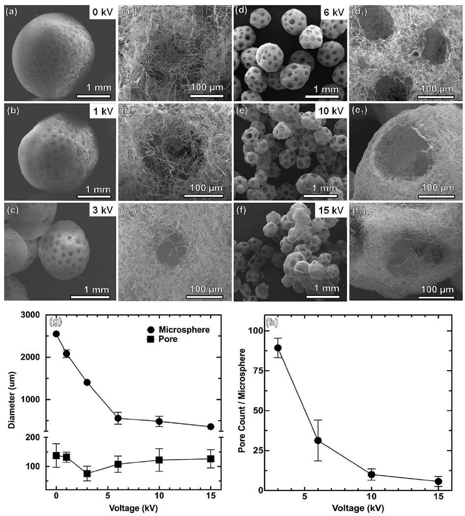
(a-a1) 0 kV. (b-b1) 1 kV. (c-c1) 3 kV. (d-d1) 6 kV. (c-c1) 10 kV. (f-f1) 15 kV. The other processing parameters: short nanofiber concentration = 20 mg/mL, solution flow rate = 2 mL/h, air flow rate = 10 mL/h, distance between nozzle and collector = 10 cm. (g, h) Pore diameter and microsphere diameter and pore count/microsphere at different voltages.
We then examined the influence of distance between the spinneret and collector and the configuration of co-axial spinneret on the formation of NMs. Figure S4 show the SEM images of collected NMs at collector gap distances of 3 cm, 5 cm, and 10 cm. At a close distance of 3 cm, we collected NMs with irregular shapes probably because the microdroplet had insufficient time to form a spherical shape prior to dripping to liquid nitrogen. Increasing the distance to 5–10 cm, however, allowed for the formation of spherical NMs, with a 10 cm distance causing a markedly higher number of pores. Droplets flight over 5 cm after detaching from the spinneret tip gave sufficient time to make droplets spherical due to surface tension before freezing in liquid nitrogen. More gas bubbles could burst out from droplets falling from 10 cm after detachment from the tip of spinneret, resulting in an increase in the number of pores. Figure S5 shows SEM images of collected NMs using three different configurations of microcapillary (core) in the spinneret including i) the core and shell needles were of equal length, ii) the core needle was 1 mm longer than the shell needle, and iii) the core needle was 1 mm shorter than the shell needle. Despite modifying the spatial arrangement of the needles during dripping, there were no significant changes in size, morphology, pore size, and number of pores/microspheres observed. However, more satellite nonporous NMs were observed when using a protruding core spinneret because the shell needle could act as another nanofiber solution dripping point (Figure S5a,a2).
In self-assembly, the molecular weight, functional groups, and solubility of the polymer are the key factors determining the NMs formation [4]. Not surprisingly, NMs fabricated by self-assembly are limited to few materials. Due to the lack of certain functional groups in popular FDA-approved polymers (e.g., PCL and poly(lactide-co-glycolide) (PLGA)), extracellular matrix (ECM) components (e.g., collagen, gelatin, and methacrylated gelatin (GelMA)), and bioactive glasses [27], forming NMs by self-assembly using these materials is incredibly challenging. Moreover, the fabrication of inorganic materials incorporated NMs could be laborious during the self-assembly process due to the phase separation in certain solvent systems. In order to demonstrate the versatility of our method, we fabricated porous NMs from a variety of materials including PCL, PLGA, collagen, gelatin, GelMA, magnetic nanoparticles, and bioactive glasses via bubble-mediated co-axial electrospray. Magneto-responsive porous NMs were fabricated with Fe2O3 nanoparticle-loaded PCL:gelatin short nanofibers. Figure S6a shows the SEM images of magneto-responsive porous Fe2O3 nanoparticle-loaded PCL:gelatin NMs while Figure S6b and Video S4 demonstrated their response to an external magnetic field. The energy-dispersive X-ray spectroscopy (EDX) analysis clearly revealed the iron content of the magneto responsive porous NMs (Figure S6c). Additionally, Figure S7 a and b show SEM images of porous PLGA:Collagen:Gelatin (PCG) NMs and (PCL:gelatin):bioglass (80:20) hybrid NMs. EDX results confirmed the presence of inorganic elements like silica (Si), strontium (Sr), calcium (Ca), and phosphorus (P) (Figure S8c). Such hybrid porous NMs could be an appealing choice for bone regeneration through a minimally invasive approach. In addition, NMs can be chemically modified post-fabrication to add functionalities. We conjugated vascular endothelial growth factor (VEGF)-mimicking peptide QK-OCTAL to porous PCL:gelatin:GelMA(1:0.5:0.5) NMs through photo-crosslinking, as described in our previous studies (Figure S8) [17]. Tetramethylrhodamine (TRITC)-labeled QK peptides (QK-OCTAL-TRITC) were used to confirm the conjugation of peptides to NMs through confocal microscopy imaging (Figure S8c–f).
To demonstrate cell delivery capabilities, human neural stem/progenitor cells (hNSCs) were seeded on both porous and nonporous PCL:gelatin NMs. Figure S9shows LIVE/DEAD staining images of cultured hNSCs on both porous and nonporous NMs at different time intervals. Almost no dead cells were observed in either group up to 10 days. The cell density on the nonporous NMs was lower compared to porous NMs. The interconnected pores in porous NMs provided more space for cell growth and enabled oxygen and nutrient diffusion, eventually forming 3D tissue spheroids. In contrast, because of the limited surface area of nonporous NMs, cells quickly reached confluency and began detaching and reattaching, forming layers of cells. These results indicated that the porous NMs supported hNSCs proliferation to form 3D microtissues. The H & E staining image clearly showed that cells grew in the inner pores of porous NMs at day 10, while cells on nonporous NMs grew only along the surface (Figure S10). We further differentiated hNSCs to neuronal lineages. Figure 4 shows the confocal images of the hNSCs on the porous and nonporous NMs after neurogenic differentiation at different time intervals. The neurite (Tuj1, green color) outgrowth on the NMs was first observed at day 10 and continued elongation to day 14, wrapping around the NMs. Given that nonporous NMs supported fewer cells, neurite outgrowths were sparse and much longer (Video S5). In contrast, due to higher cell counts and porous architectures in porous NMs, dense neurites were seen throughout the microspheres (Video S6). Moreover, confocal microscopy images showing the Tuj1 expression of hNSCs seeded on porous NMs after culturing in the neuronal differentiation medium for 14 days in different depths of microspheres (Figure S11). Damaged brain tissue regeneration has been a therapeutic priority often halted by the complex structures and biochemical cues of brain and limited capacity of central nervous system to regenerate [28]. Recently, biomaterial-assisted stem cell implantations set milestones in recovering neurological functions in some damaged brain tissue [29]. The injectable hNSC-seeded porous NMs at different levels of neuronal differentiation could have great potential for treating neurodegenerative diseases and traumatic brain injuries.
Figure 4. Confocal microscopy images showing the Tuj1 expression of hNSCs seeded on porous and nonporous PCL:gelatin (1:1) NMs after culturing in the neuronal differentiation medium for 10 and 14 days.
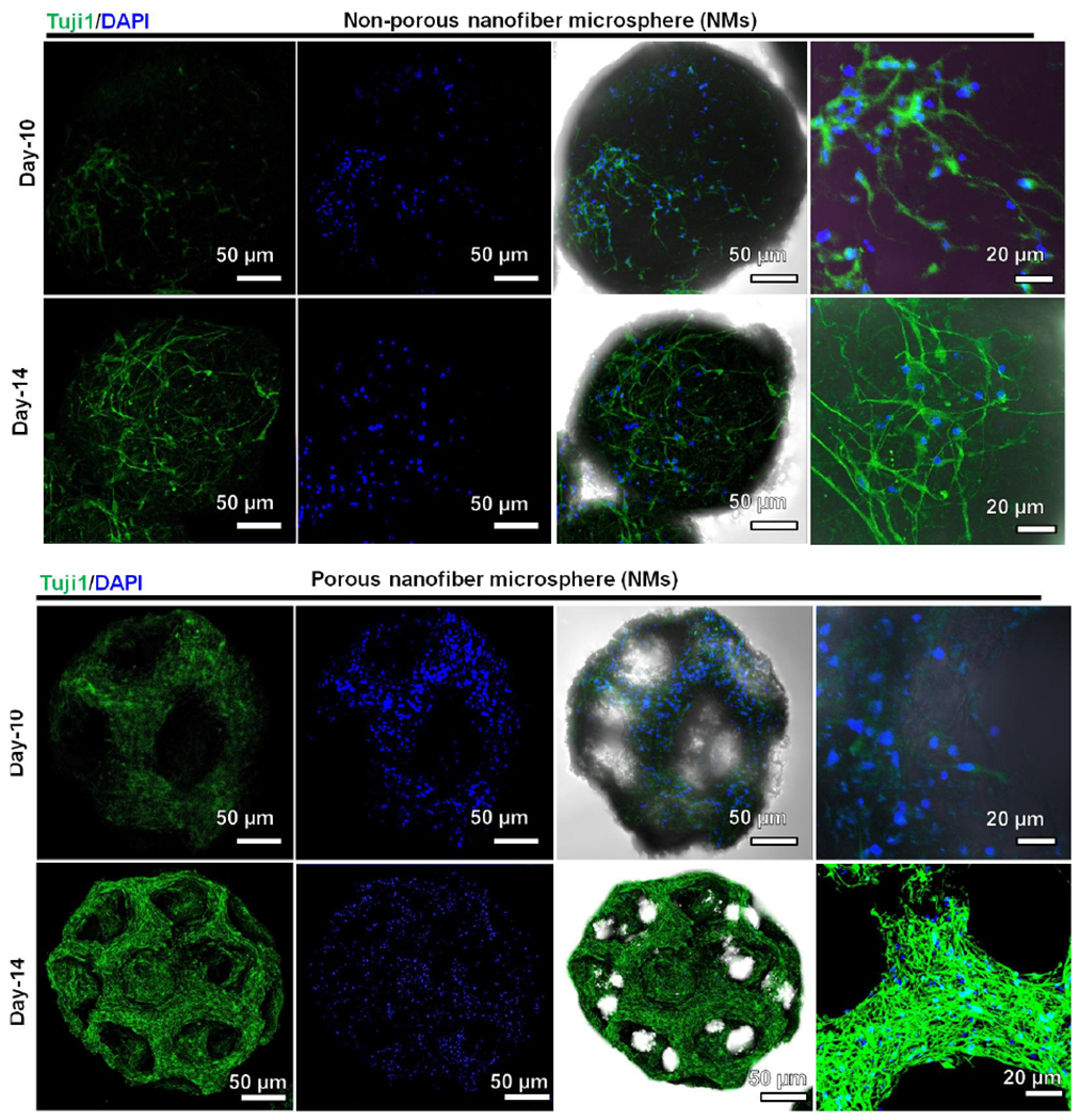
The cells were stained with Tuj1 antibody in green and counterstained with DAPI in blue. The right two columns show merged images of fluorescent images of Tuj1 antibody staining and DAPI staining and the brightfield images.
To examine NMs as fillers for tissue repair, we injected porous and nonporous NMs subcutaneously to rats as acellular scaffolds (Figure S12). Impressively, H & E staining showed many host cells infiltrated and migrated throughout the porous NMs after implantation for 1 week, while cell infiltration was less visible in nonporous NMs (Figure 5, a,b,e,f). After 2 weeks, cells completely penetrated throughout the porous NMs, with only superficial penetration on nonporous NMs (Figure 5, c,d,g,h). The open porous architecture of the NMs enhanced cell infiltration and organization, while forming new 3D tissues entirely from host cells. Further, Masson’s staining showed corresponding collagen deposition and neovascularization within the injected NMs (Figure 5, i–l). Collagen deposition mainly occurred around the nonporous NMs, however, collagen deposition and blood vessel formation occurred inside the porous NMs after 2 weeks of implantation. Based on the in vitro and in vivo results, we can conclude that cells only grow on the surface of nonporous NMs, but can grow on the surface of and throughout the interconnected pores of porous NMs after subcutaneous implantation (Figure 5, m,n). These results indicate that injection of such porous NMs to tissue defects could rapidly form new tissues through cell infiltration, ECM deposition, and neovascularization. In addition, these porous NMs can be functionalized with biological cues to further promote host cell recruitment, ECM production, and angiogenesis. We successfully demonstrated neurite outgrowth on both porous and non-porous microspheres, and the injectability was also demonstrated by subcutaneous injection to rats. We will test the efficacy of stem cells-laden porous nanofiber microspheres in a stroke rat model in the future work.
Figure 5. Subcutaneous injection of porous and nonporous NMs to rats for 1 and 2 weeks.
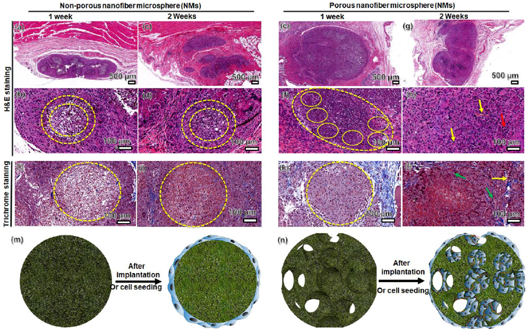
(a-h) H & E staining of porous and nonporous NMs and their surrounding tissues (yellow dashed circles). (i-l) Masson’s trichrome staining indicates collagen deposition (green arrow) and neovascularization (yellow arrow) within the porous and nonporous NMs. (m-n) Schematic illustrating cell distribution on nonporous and porous NMs after cell seeding in vitro and subcutaneous injection to rats, suggesting cellular infiltration and neovascularization in porous NMs.
In summary, we for the first time demonstrated a simple and versatile approach for engineering NMs with controlled size, predesigned structure, and desired composition by co-axial electrospraying of air in the core and a short nanofiber solution in the shell, respectively. Varying parameters, such as airflow rates and applied voltages, enables a tunability that is yet to be reported in engineering NMs. We also demonstrated that NMs serving as cell carriers can enhance expansion and differentiation, suggesting the potential use for stem cell therapies. Moreover, we demonstrated the ability to fabricate porous NMs from a broad range of materials with different functionalities, including magneto-responsive, functional peptide-conjugated, ECM composition-mimicking, and inorganic/organic hybrid NMs. The in vitro and in vivo studies showed that the open porous architecture of the NMs provided an ideal matrix for cellular infiltration and integration with host tissue. The NMs developed in this study could be potentially used in combination with drugs, biologics, and cells for the treatment of many diseases or injuries in a minimally invasive manner.
Supplementary Material
Acknowledgments
This work was supported by grants from the National Institute of General Medical Science (NIGMS) at the NIH (R01GM123081), National Institute of Dental and Craniofacial Research (NIDCR) at the NIH (1R21DE027516), NE LB606, and startup funds from the University of Nebraska Medical Center.
Contributor Information
Johnson V. John, Department of Surgery-Transplant and Mary & Dick Holland Regenerative Medicine Program, College of Medicine, University of Nebraska Medical Center, Omaha, NE 68198, USA
Alec McCarthy, Department of Surgery-Transplant and Mary & Dick Holland Regenerative Medicine Program, College of Medicine, University of Nebraska Medical Center, Omaha, NE 68198, USA.
Hongjun Wang, Department of Surgery-Transplant and Mary & Dick Holland Regenerative Medicine Program, College of Medicine, University of Nebraska Medical Center, Omaha, NE 68198, USA.
Shixuan Chen, Department of Surgery-Transplant and Mary & Dick Holland Regenerative Medicine Program, College of Medicine, University of Nebraska Medical Center, Omaha, NE 68198, USA.
Yajuan Su, Department of Surgery-Transplant and Mary & Dick Holland Regenerative Medicine Program, College of Medicine, University of Nebraska Medical Center, Omaha, NE 68198, USA.
Ethan Davis, Department of Mechanical and Materials Engineering, College of Engineering, University of Nebraska Lincoln, Lincoln, NE 68588, USA.
Xiaowei Li, Department of Neurological Sciences, and Mary & Dick Holland Regenerative Medicine Program, College of Medicine, University of Nebraska Medical Center, Omaha, NE 68198, USA.
Jae Sung Park, Department of Mechanical and Materials Engineering, College of Engineering, University of Nebraska Lincoln, Lincoln, NE 68588, USA.
Richard A. Reinhardt, Department of Surgical Specialties, College of Dentistry, University of Nebraska Medical Center, Omaha, NE 68198, USA
Jingwei Xie, Department of Surgery-Transplant and Mary & Dick Holland Regenerative Medicine Program, College of Medicine, University of Nebraska Medical Center, Omaha, NE 68198, USA.
References
- [1].Deng H, Li X, Peng Q, Wang X, Chen J, Li Y, Angew. Chem. Int. Ed 2005, 44, 2782. [DOI] [PubMed] [Google Scholar]
- [2].Deng Y, Qi D, Deng C, Zhang X, Zhao D, J. Am. Chem. Soc 2008, 130, 28. [DOI] [PubMed] [Google Scholar]
- [3].Castillo-Orozco E, Kar A, Kumar R, Sci Rep. 2017, 7, 5144. [DOI] [PMC free article] [PubMed] [Google Scholar]
- [4].Liu X, Jin X, X Ma P, Nat. Mater 2011, 5, 398. [DOI] [PMC free article] [PubMed] [Google Scholar]
- [5].Zhang Z, Eyster TW, Ma PX, Nanomedicine. 2016, 11, 1611. [DOI] [PMC free article] [PubMed] [Google Scholar]
- [6].Zhang Z, Marson RL, Ge Z, Glotzer SC, Ma PX, Adv. Mater 2015, 27, 3947. [DOI] [PMC free article] [PubMed] [Google Scholar]
- [7].Zhou Y, Gao H-L, Shen L-L, Pan Z, Mao L-B, Wu T, He J-C, Zou D–H, Zhang Z, Yu S–H, Nanoscale 2016, 8, 309. [DOI] [PubMed] [Google Scholar]
- [8].Liu X, Ahmed A, Wang Z, Zhang H, Chem. Commun 2015, 51, 16864. [DOI] [PubMed] [Google Scholar]
- [9].Duan B, Zheng X, Xia Z, Fan X, Guo L, Liu J, Wang Y, Ye Q, Zhang L, Angew. Chem. Int. Ed 2015, 54, 5152. [DOI] [PubMed] [Google Scholar]
- [10].Kuang R, Zhang Z, Jin X, Hu J, Gupte MJ, Ni L, Ma PX, Adv. Healthc. Mater 2015, 4, 1993. [DOI] [PMC free article] [PubMed] [Google Scholar]
- [11].Zhang Z, Gupte MJ, Jin X, Ma PX, Adv. Funct. Mater 2015, 25, 350. [DOI] [PMC free article] [PubMed] [Google Scholar]
- [12].Su X, Tan M, Duan B, Cai J, Jiang W Zhang L, J. Mater. Chem. B 2019,7, 5190. [DOI] [PubMed] [Google Scholar]
- [13].Boda SK, Li X, Xie J, J. Aerosol Sci 2018, 125, 164–181. [DOI] [PMC free article] [PubMed] [Google Scholar]
- [14].Xie J, Jiang J, Davoodi P, Srinivasan MP, Hwang CH, Chem. Eng. Sci 2015, 125, 32–57. [DOI] [PMC free article] [PubMed] [Google Scholar]
- [15].Xie J. Marijnissen JCM, Wang CH, Biomaterials. 2006, 27, 3321–3332. [DOI] [PubMed] [Google Scholar]
- [16].Boda S, Chen S, Chu K, Kim HJ, Xie J, ACS Appl. Mater. Interfaces 2018, 10, 25069. [DOI] [PMC free article] [PubMed] [Google Scholar]
- [17].John JV, Choksi M, Chen S, Boda SK, Su Y, McCarthy A, Teusink MJ, Reinhardt RA, Xie J, Nanomedicine: NBM. 2019, 22, 102081. [DOI] [PMC free article] [PubMed] [Google Scholar]
- [18].Kankala RK, Zhao J, Liu CG, Song XJ, yang DY, Zhu K, Wang SB, Zhang YS, Chen AZ, Small. 2019, 15, 1901397. [DOI] [PMC free article] [PubMed] [Google Scholar]
- [19].Wei DX, Dao JW, Chen GQ, Adv. Mater 2018, 30, 1802273. [DOI] [PubMed] [Google Scholar]
- [20].Barbetta A, Carrino A, Costantini M, Dentini M, Soft Matter. 2010, 6, 5213–5224. [Google Scholar]
- [21].Zhang R, Hu R, Li X, Zhen Z, Xu Z, Li N, He L, Zhu H, Adv. Funct. Mater 2018, 28, 1705879. [Google Scholar]
- [22].Costantini M, Colosi C, Jaroszewicz J, Tosato A, Swięszkowski W, Dentini M, Garstecki P, Barbett A, ACS Appl. Mater. Interfaces 2015, 7, 23660–23671. [DOI] [PubMed] [Google Scholar]
- [23].Guo L, Zhang S, Cheng L, Front. Energy 2011, 5, 250. [Google Scholar]
- [24].Icart I, Arques D, Computers & Graphics. 1999, 23, 405. [Google Scholar]
- [25].Kuck H, Vogelgsang C, Greiner G, Proceedings of Graphics Interface. 2002, 10.20380/GI2002.10. [DOI] [Google Scholar]
- [26].Durian DJ, Phys. Rev. Lett 1995, 75, 4780. [DOI] [PubMed] [Google Scholar]
- [27].Durikovi R, Comput Graph Forum. 2001, 20, 67. [Google Scholar]
- [28].Weng L, Boda SK, Wang H, Teusink MJ, Shuler FD, Xie J, Adv. Healthcare Mater 2018, 7, 1701415. [DOI] [PMC free article] [PubMed] [Google Scholar]
- [29].Ballabh P, Braun A, Nedergaard M, Neurobiol. Dis 2004, 16, 1. [DOI] [PubMed] [Google Scholar]
- [30].Guan J, Zhu Z, Zhao RC, Xiao Z, Wu C, Han Q, Chen L, Tong W, Zhang J, Han Q, Gao J, Feng M, Bao X, Dai J, Wang R, Biomaterials. 2013, 34,5937. [DOI] [PubMed] [Google Scholar]
Associated Data
This section collects any data citations, data availability statements, or supplementary materials included in this article.


