Conspectus
In recent years, a steadily growing number of chemists, from both academia and industry, have dedicated their research to the development of continuous flow processes performed in milli- or microreactors. The common availability of continuous flow equipment at virtually all scales and affordable cost has additionally impacted this trend. Furthermore, regulatory agencies such as the United States Food and Drug Administration actively encourage continuous manufacturing of active pharmaceutical ingredients (APIs) with the vision of quality and productivity improvements. That is why the pharmaceutical industry is progressively implementing continuous flow technologies. As a result of the exceptional characteristics of continuous flow reactors such as small reactor volumes and remarkably fast heat and mass transfer, process conditions which need to be avoided in conventional batch syntheses can be safely employed. Thus, continuous operation is particularly advantageous for reactions at high temperatures/pressures (novel process windows) and for ultrafast, exothermic reactions (flash chemistry).
In addition to conditions that are outside of the operation range of conventional stirred tank reactors, reagents possessing a high hazard potential and therefore not amenable to batch processing can be safely utilized (forbidden chemistry). Because of the small reactor volumes, risks in case of a failure are minimized. Such hazardous reagents often are low molecular weight compounds, leading generally to the most atom-, time-, and cost-efficient route toward the desired product. Ideally, they are generated from benign, readily available and cheap precursors within the closed environment of the flow reactor on-site on-demand. By doing so, the transport, storage, and handling of those compounds, which impose a certain safety risk especially on a large scale, are circumvented. This strategy also positively impacts the global supply chain dependency, which can be a severe issue, particularly in times of stricter safety regulations or an epidemic. The concept of the in situ production of a hazardous material is generally referred to as the “generator” of the material. Importantly, in an integrated flow process, multiple modules can be assembled consecutively, allowing not only an in-line purification/separation and quenching of the reagent, but also its downstream conversion to a nonhazardous product.
For the past decade, research in our group has focused on the continuous generation of hazardous reagents using a range of reactor designs and experimental techniques, particularly toward the synthesis of APIs. In this Account, we therefore introduce chemical generator concepts that have been developed in our laboratories for the production of toxic, explosive, and short-lived reagents. We have defined three different classes of generators depending on the reactivity/stability of the reagents, featuring reagents such as Br2, HCN, peracids, diazomethane (CH2N2), or hydrazoic acid (HN3). The various reactor designs, including in-line membrane separation techniques and real-time process analytical technologies for the generation, purification, and monitoring of those hazardous reagents, and also their downstream transformations are presented. This Account should serve as food for thought to extend the scope of chemical generators for accomplishing more efficient and more economic processes.
1. Introduction
The most direct, atom-economic, and sustainable synthetic routes frequently require the use of highly reactive, often toxic and short-lived reagents. Despite their advantages, many of such hazardous reagents are banned from laboratories in both industry and academia in a conventional chemical environment, and alternative routes employing easier to handle materials are chosen instead. However, this strategy is unattractive with respect to scale-up because it generally proves to be more laborious, generates more waste material, and is thus neither cost nor environmentally effective.
The concern toward the utilization of hazardous materials is not only related to their handling by the operator but also to their transportation and on-site storage, in particular on a large scale. Indeed, many potentially powerful reagents are imposed with stringent transport, storage, and preventive maintenance restrictions or are even not amenable to be transported or stored due to their instability and/or toxicity. The transportation of dangerous goods is strictly controlled and governed through national and international regulations.1 Each mode of transport has its own set of regulations, which vary considerably from one country to another and are revised continuously.1
In addition, the high dependency on the global supply chain, changing market situation, and quality of the shipped material has a significant impact on the end-user. This vulnerability becomes even more severe nowadays because authorities in low-cost countries increasingly tighten environmental and safety controls on raw material manufacturers.2 The prospect of keeping the supply chain short is therefore of major interest to the chemical industry. By eliminating bottlenecks in the supply chain, the agility of production is increased, and a rapid response to a changing market is facilitated.
To overcome the transport, storage, and handling predicament of hazardous reagents, they are best produced in situ from benign precursors, on-site and on-demand whenever they are needed and in volumes that match the demand.3 The risk is further reduced through real-time use of the dangerous chemical by an immediate transformation into a nonhazardous product directly upon its generation. The safest way to do so is their synthesis by continuous flow processes in small-structured reactors (e.g. microreactors).4 This concept of continuous in situ production of hazardous materials is commonly referred to as the “generator” of this material.5 The defining characteristic of these flow reactors is their comparatively small reactor volume which minimizes the severity in case of an accident because less material and energy is released. In addition, head space issues are eliminated, and an extraordinary heat and mass transport is achieved. As a result, hazardous reagents and process conditions can be safely employed which otherwise would be difficult, if not impossible, to implement in a traditional batch setup. Continuous processing therefore opens up the toolbox of “forbidden chemistries” to be safely carried out.4
For the past 10 years, a significant portion of our group’s research has been directed toward the generation of hazardous and/or unstable reagents in continuous flow environments, many times in extreme temperature and pressure regimes. As safety is one of the main drivers to implement continuous processes, in particular in the pharmaceutical industry, hazardous but more atom- and cost-economic routes are increasingly incorporated into the synthesis. Therefore, continuously broadening the chemical generator scope is of paramount importance. In this Account, numerous contributions to this field are highlighted with an emphasis on chemical generator concepts that were developed within the past decade in our group for continuous on-site on-demand production of toxic, explosive, and short-lived reagents. For further hazardous chemistries performed in continuous flow environments, several other review articles are recommended.4
2. Chemical Generators for Hazardous Reagents
Classical chemical generators for the continuous production of simple, reactive molecules such as F2, O2, O3, or H2 have been in use for decades. Most of them operate via electrolysis and are commercially available. However, with the growing interest in continuous flow operations by the pharmaceutical industry for active pharmaceutical ingredient (API) manufacturing and the accompanied demand to access new process windows,6 custom-built generators for explosive, toxic, and short-lived reagents are constantly being developed. Both the now common access to flow equipment and technological advances in this field led to the emergence of a new generation of chemical generators. Figure 1 depicts the general concept for such generators for the on-site on-demand production of hazardous reagents. They are generated from nontoxic, readily accessible and ideally low-cost precursors and, if necessary, purified in-line to produce a continuous stream of the reagent, which is then further consumed by an appropriate substrate in a downstream reaction in a fully contained fashion. Before product collection, an in-line quench to destroy any remaining hazardous material can be incorporated.
Figure 1.
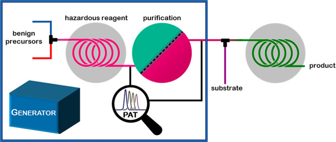
Concept of a chemical generator with subsequent consumption of the hazardous reagent to the desired product. PAT: process analytical technology.
Additionally, by integrating process analytical technologies (PAT), real-time data can be acquired for process monitoring and process control for ensuring product quality.7 Rapid in-line reaction analysis is of particular importance when working with highly hazardous material, transient intermediates, or high temperature/pressure systems, because standard off-line sampling techniques are highly undesirable. In-line PAT tools such as NMR, UV/vis, or IR are particularly easy to implement into continuous flow reactors.8 Furthermore, process control systems can be employed to automate the process.9
A reagent produced in a chemical generator often needs in-line purification to remove undesired byproducts and to transfer it into a solvent suitable for subsequent downstream transformations. One of the most powerful purification methods relies on the use of membranes for the separation of a desired reagent or intermediate.10 Two membrane-based separation techniques have been used to conquer the field of continuous flow synthesis: liquid–liquid and gas–liquid separators. The liquid–liquid separation technique depends on the exploitation of surface forces and the difference in wetting properties of the liquids onto a porous membrane.11 This concept is typically applied when the reagent is generated within an aqueous environment. After extraction into a suitable organic solvent, membrane separation takes place: the organic or “wetting” phase passes through the hydrophobic membrane, while the aqueous phase is retained. On the other hand, the gas–liquid separation takes advantage of the selective permeability of the membrane for hydrophobic low molecular weight compounds in gaseous form. The most commonly employed semipermeable membrane for the separation and purification of hazardous reagents is the gas-permeable Teflon AF-2400 membrane, which is housed inside the so-called tube-in-tube reactor.12 In this device, the gaseous reagent is generated inside the inner AF-2400 tubing and then diffuses through this membrane and instantly reacts with the substrate that is carried within the outer gas impermeable tubing.
Pursuant to our definition, a modern chemical generator should guarantee the most atom- and cost-effective route toward the desired end-product. Therefore, the hazardous material has to be a simple, low molecular weight and versatile compound and be produced from inexpensive, benign precursors. Where necessary, the reagent can be purified/separated in-line prior to the downstream transformation. We categorize these generators according to reagent stability into three classes: generators for (1) stable reagents, (2) reagents with limited stability, and (3) unstable reagents (Figure 2). All three classes are discussed in this Account (Figure 3).
Figure 2.
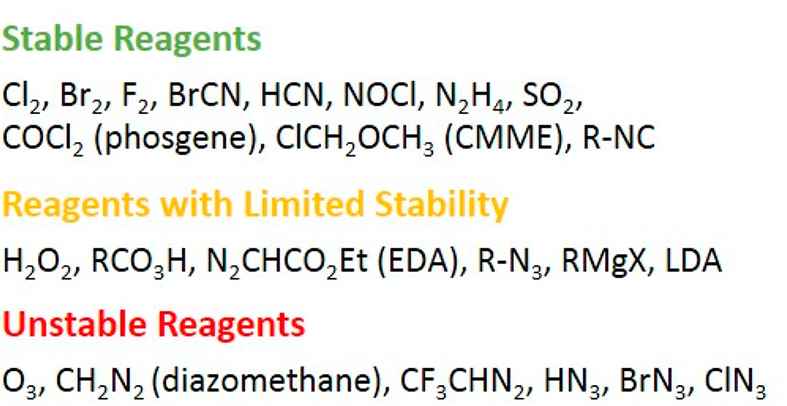
Classification of hazardous reagents according to their stability.
Figure 3.
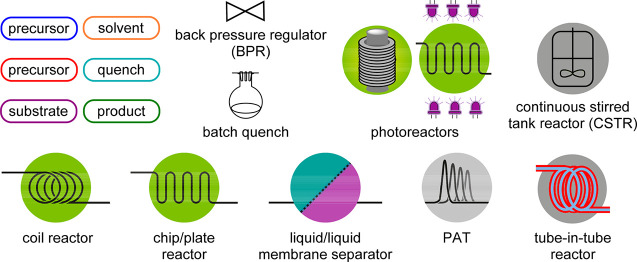
Overview of used continuous flow icons.
2.1. Generators for Stable Reagents
These reagents are commercially available in their pure form and can be shipped and stored, although stringent restrictions are imposed. To overcome these sometimes exceptional measures, it is highly desirable to generate those reagents in situ and on-demand for both manufacturing and laboratory use.
Cyanogen bromide (BrCN) is a solid that sublimes at room temperature and is acutely toxic. Pure BrCN is stable for longer periods if stored under dry conditions at 2–8 °C, but impurities catalyze its exothermic and explosive trimerization to cyanuric bromide. Furthermore, it is decomposed gradually by water/moisture and rapidly by acids to highly toxic HCN and corrosive HBr. BrCN is a versatile reagent in organic synthesis as an electrophilic cyanide source to generate a variety of products.13 We developed a BrCN generator that produces this material from aqueous Br2 and KCN solutions (Scheme 1).14 A solution of pure BrCN in dichloromethane (DCM) was obtained after an in-line extraction using a glass microreactor chip and purification with a liquid–liquid membrane separator unit. Furthermore, the generated BrCN was monitored and quantified via in-line FTIR analysis. The such generated 0.7 M BrCN solution was further employed in the downstream reaction with diamines or aminoalcohols to obtain five- and six-membered cyclic guanidines and amidines (Scheme 1).
Scheme 1. Br2 and BrCN Generators Connected in Series for the Synthesis of Cyclic Guanidines.
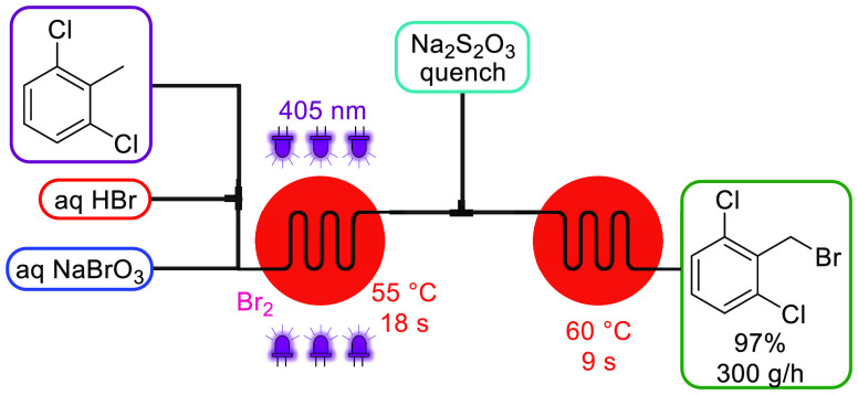
Because this generator model employs elemental bromine (Br2), which is also an exceedingly undesirable reagent to handle and more particularly to transport (it is commonly carried in lead-lined steel tanks supported by strong metal frames), we also designed a continuous Br2 generator employing the well-established bromate–bromide synproportionation under acidic conditions.14 An aqueous feed of NaBrO3 and NaBr was mixed with aqueous HBr at equal flow rates to generate a 1 M Br2 solution. This module can either be used for performing brominations or can be coupled upstream to the BrCN generator as a Br2 feed (Scheme 1). Notably, by employing the in-series concept, a higher BrCN concentration (0.8 M) was achieved due to the increased solubility of Br2 in water. We then further advanced the bromine generator concept for highly intensified photochemical benzylic bromination reactions employing a plate-based photochemical reactor.15 By mixing the neat organic stream with HBr prior entering the reactor, interphase mixing was improved. That not only allowed Br2 to be generated within the mixing structures in a more effective (3.8 M) and uniform way but also allowed omission of NaBr that was previously necessary to improve the water solubility of Br2. In addition, because of the enhanced mass transfer within the reactor’s internal mixing structure, generated HBr is recycled via backmixing into the aqueous phase, thus resulting in a reduced HBr loading. With the setup depicted in Scheme 2, neat 2,6-dichlorotoluene was converted to the benzyl bromide derivative, an important API building block for inhalation medicines, within a residence time of only 18 s and a productivity of 300 g/h. Excess Br2 was quenched in-line with sodium thiosulfate (Na2S2O3). Similar Br2 generators using either NaOCl16 or H2O217 as oxidant have also been reported.
Scheme 2. Br2 Generator and Its Use in Photochemical Benzylic Brominations.
Along similar lines, elemental chlorine (Cl2) can be generated. Chlorine is the most atom economic reagent to generate chlorinated compounds and, furthermore, is a cheap and powerful oxidation agent. However, Cl2 gas is highly toxic and corrosive, and strict regulations must be followed, i.e. production facilities normally need to be isolated and staff specially equipped and trained. In 2016, we demonstrated that Cl2 was generated almost instantaneously and in ca. 90% yield at room temperature by mixing aqueous solutions of sodium hypochlorite (NaOCl, bleach) and HCl (Scheme 3).18 It was then extracted from the water phase into an organic phase, and the two phases were separated in a liquid–liquid membrane separator. The byproduct of the reaction (aq NaCl) is removed with the aqueous waste stream, while the Cl2 in the organic phase can be directly utilized for subsequent chlorination and oxidation reactions. The selective oxidation of secondary alcohols employing the in situ formed chlorine–pyridine complex (Cl2:Py) is illustrated in Scheme 3.
Scheme 3. Cl2 Generator and Its Use in the Selective Oxidation of Secondary Alcohols.
Nitrosyl chloride (NOCl) is a toxic gas and has a corrosiveness comparable to aqua regia. It can be stored only in nickel-based alloys such as Monel, and its commercial availability is thus limited. NOCl behaves as an electrophile and is i.e. used for the synthesis of oximes from alkenes, ketones, or alkanes. We reported the generation of NOCl from aqueous sodium nitrite (NaNO2) and HCl as inexpensive and readily available precursors in 2019 (Scheme 4).19 After an essentially spontaneous formation of NOCl, it was rapidly extracted into DCM and separated from the aqueous phase in a liquid–liquid membrane separator. Before consumption by a substrate, the NOCl concentration was monitored in-line with a custom-built UV/vis flow cell made of NOCl-compatible material. A plate-based photochemical reactor was finally integrated to perform the downstream chemistry, the photochemical transformation of cyclohexane to cyclohexanone oxime, which is an important industrial building block toward ε-caprolactam (Scheme 4).
Scheme 4. NOCl Generator and Its Use in the Photochemical Oximation of Cyclohexane.
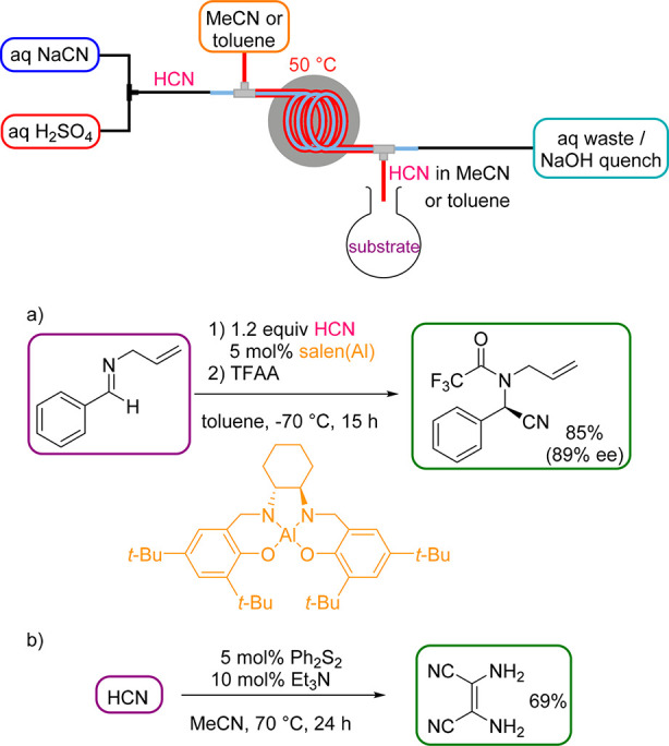
Hydrogen cyanide (HCN) is a highly valuable and atom-economic reagent for organic synthesis (e.g., synthesis of cyanohydrin precursors or (hydro)cyanations), but also a highly poisonous and volatile liquid that turns into a gas at 26 °C. In pure form, HCN is stable but it polymerizes exothermally in the presence of basic materials. Nowadays, the Andrussow and Degussa processes account for almost the entire large-scale production of pure HCN (e.g., 450 t/a are shipped in gas cylinders by DuPont).3 Its use on laboratory scale, on the other hand, is considered too dangerous and is thus significantly underutilized in organic synthesis. The first HCN generator was reported by Stevens and Acke in 2007.20 HCN was produced within the same tubing as the HCN consuming reaction took place, which can cause compatibility issues. To generate anhydrous HCN, crucial for a variety of transformations, we developed a safe protocol for the generation and separation of HCN within the tube-in-tube reactor.21 By mixing aqueous feeds of NaCN and H2SO4, HCN is formed, diffuses at 50 °C in its gaseous form through the membrane into a carrier solvent, and finally exits the reactor into a flask containing the substrate (Scheme 5). This semibatch “HCN on tap” configuration was preferred for most transformations, because the exceedingly long reaction times of up to 24 h are usually not tolerable for a fully continuous flow approach (Scheme 5). In addition, subzero temperatures in an aqueous reaction medium, as in the asymmetric Strecker reaction (Scheme 5a), are not feasible inside the tube-in-tube.
Scheme 5. Anhydrous HCN Generator (HCN on Tap) and Its Use in the Asymmetric Strecker Reaction (a) and Synthesis of Diaminomaleonitrile (b).
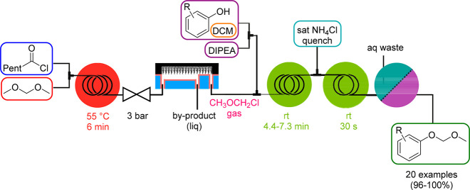
A separation technique that is not relying on a membrane was developed by Kim and coworkers for the generation of chloromethyl methyl ether (CMME), which is highly carcinogenic and genotoxic, is used as an alkylating agent and is renowned for the introduction of the methoxymethyl (MOM) protecting group. In 2016, they introduced the so-called μ-TES (micrototal envelop system) format for the safe generation, separation/purification, consumption, and quenching of CMME (Scheme 6).22 Key to this strategy was the use of a membrane-free superamphiphobic SiNW (silicon nanowire) microseparator where separation occurs at the interface of the stable gas–liquid laminar flow. CMME was generated from hexanoyl chloride and dimethoxymethane by heating in a coil reactor. The exiting stream was fed into the SiNW separator, where CMME gas was separated from the liquid reaction mixture, subsequently combined with the reagent stream for MOM protection, and finally quenched in line with an ammonium chloride solution (Scheme 6). The products were separated by an ultimate liquid–liquid membrane extraction step.
Scheme 6. CMME Generator and Its Use in Alkoxyalkylation Reactions (MOM Protection).
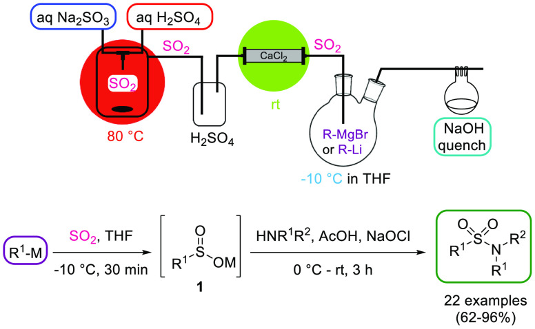
Sulfur dioxide (SO2) can be shipped and stored as a compressed liquefied gas but necessitates purpose-built facilities and dedicated equipment. Moreover, in the EPA Risk Management Planning program, SO2 is ranked among the top ten chemicals involved in industrial accidents.3 Its sparse application on lab-scale is due to its corrosiveness, its considerable toxicity at high concentrations, and the resulting demanding safety measures. Nonetheless, SO2 is an atom-efficient and inexpensive reagent and is used in a variety of organic transformations such as the synthesis of H2SO4, sulfonyl chlorides or sulfonamides. In 2020, Ramalingam, Chen, and coworkers developed a semibatch protocol for the on-demand generation of SO2 from readily available sodium sulfite (Na2SO3) and H2SO4 (Scheme 7).23 SO2 gas was produced instantaneously within the T-mixer inside a closed vessel up to a productivity of 1.5 mmol/min. SO2 was further dried by passing through a H2SO4 trap and a packed-bed reactor filled with CaCl2 before reacting with an organometallic reagent to form the corresponding sulfinate 1, which was subsequently converted to the respective sulfonamide (Scheme 7).
Scheme 7. SO2 Generator and Its Use for the Synthesis of Sulfonamides.
Another reagent that falls into this category is phosgene (COCl2). Phosgene is a highly toxic gas that can be shipped and stored when converted into a liquid by cooling and pressurization. Its production and storage require extraordinary measures and it is under various transportation restrictions. Consequently, most phosgene is consumed on-site. Phosgene is an important industrial chemical, with several million tons produced globally each year,24 and is predominantly used for the synthesis of isocyanates. However, on lab-scale, it finds limited use because of the accompanied hazards. A safe continuous process was reported by Jensen and coworkers in 2001 where phosgene was generated from Cl2 and carbon monoxide (CO) under activated carbon catalysis in a silicon-based packed-bed reactor with a productivity of 1–11 g/h.25 By utilizing a simpler reactor setup, the Takahashi group developed a route that uses less-toxic triphosgene as phosgene precursor, which decomposes to phosgene inside the microreactor upon mixing with an amine base.26
2.2. Generators for Reagents with Limited Stability
This type of reagents is too unstable to be transported or stored in their pure form. Therefore, to minimize the hazard of exothermic decomposition and in further consequence violent explosion, they often are delivered in diluted form. The shipping is restricted, and based on the concentration, various safety measures apply.
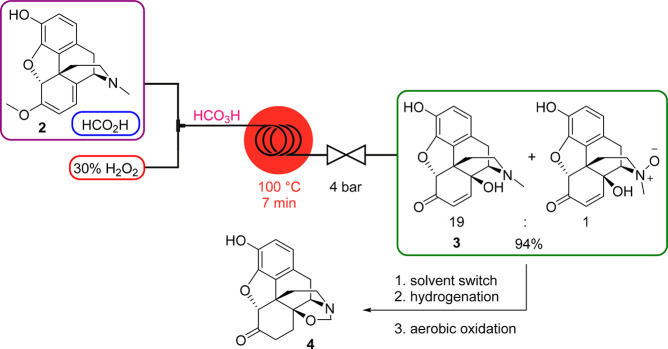
Peracids are strong oxidizing reagents used for epoxidations, hydroxylations, and the Baeyer–Villiger oxidation. They are also very unstable and, depending on the concentration, prone to explosive decompositions. Performic acid (HCO3H) in concentrations >50% is highly reactive: it readily decomposes upon heating and explodes when rapidly heated to 80–85 °C; at room temperature, it may ignite or explode when combined with flammable substances. In view of our group’s interest in the synthesis of opioid-derived APIs,27 a telescoped continuous process toward a noroxymorphone precursor (4) was established that comprised the C14 hydroxylation of naturally occurring oripavine (2) employing HCO3H as the key step.28 Performic acid was generated in situ from formic acid (HCO2H) and 30% aqueous hydrogen peroxide (H2O2) which then rapidly oxidized the diene moiety of oripavine at 100 °C to provide 14-hydroxymorphinone (3) and the corresponding N-oxide (Scheme 8). A subsequent continuous solvent switch, hydrogenation in a packed-bed hydrogenator, and palladium catalyzed N-methyl oxidation furnished 1,3-oxazolidine derivative 4.
Scheme 8. HCO3H Generator and Its Use in the C14 Hydroxylation of Oripavine toward a Telescoped Synthesis of 1,3-Oxazolidine 4.
Similar continuous flow approaches for generating peracids in situ were also reported by Kolehmainen and coworkers29 and Siegfried Ltd.30
Lithium diisopropylamide (LDA) is pyrophoric as a solid, but its solutions are generally not; therefore, it is commercially typically available as a solution in THF/hexanes. However, because LDA solutions are known to be unstable upon prolonged storage, it is generally prepared in situ from diisopropylamine and n-butyl lithium (n-BuLi). To control the exotherm produced during the LDA generation and enable its safe production on larger scale, several research groups have developed continuous flow strategies.31 We described a multistep protocol where in situ generated LDA is immediately consumed by an ester to form the corresponding highly reactive lithium enolate intermediate 5 (Scheme 9).32 The process is then integrated with an electrophilic addition step and an in-line water quench to furnish the α-functionalized esters 6. Because of the enhanced mass transfer, higher temperatures compared to batch (0 vs −78 °C) can be applied for both LDA and enolate generation.
Scheme 9. LDA Generator with Integrated Enolate Formation and Electrophilic Addition toward α-Functionalized Esters.
2.3. Generators for Unstable Reagents
These reagents are generally banned from transport and storage because they are too dangerous and/or too short-lived. They are therefore not commercially available in any form. The hazardous nature of these compounds has severely limited their use in laboratories, particularly in industry, in the past.
Diazo compounds belong to the most versatile reagents in the organic chemistry portfolio.33 They are used, i.e., for X–H insertions, ylide formation, cyclopropanations, and cycloadditions. Whereas diazoalkanes are too hazardous and unstable to be purchased (vide infra), α-diazocarbonyls are comparatively more stable and thus a few can be acquired in dilute (10–15%) solutions. One example is ethyl diazoacetate (EDA), which is routinely handled on a laboratory scale, while its presence in a chemical plant causes problems when applied in batch mode. Among the many reported continuous flow processes to generate EDA,34 the most atom-economic route is the diazotation of glycine ethyl ester hydrochloride with NaNO2.5,35 The such generated EDA was purified by an integrated liquid–liquid membrane separation unit and was immediately used for further follow-up chemistries.5,35
Diazomethane (CH2N2) is the simplest but also the most hazardous diazo compound: it is an extremely toxic gas, a potent carcinogen, and because of its extreme sensitivity to explosive decomposition, it is challenging to handle and store. On the other hand, it is a versatile and the most atom-economic C1 building block that provides typically fast and clean reactions, often producing only nitrogen as a byproduct. Traditional CH2N2 production by distillation is discouraged by industry on both lab and production scale due to the enormous safety risks involved. Therefore, different methods to generate CH2N2 by base-mediated decomposition of N-nitroso-N-methyl amine precursors in continuous flow systems have emerged over the last few years by using either standard (micro)reactors or membrane technology.36 The safest and thus most prominently employed precursor is N-methyl-N-nitroso-p-toluenesulfonamide (Diazald) but also N-nitroso-N-methyl urea (NMU), a toxic and explosive compound itself, can be used when generated upstream in situ from benign and cheap N-methyl urea.37,38
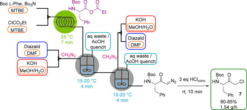
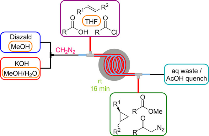
As of 2013, we commenced extensive studies on the development of anhydrous CH2N2 generators by membrane separation techniques. Initially, we employed the tube-in-tube reactor to separate gaseous CH2N2 from the aqueous reaction stream carried within the inner membrane tubing.39 Downstream transformations that took place inside the outer tubing included the methylation of carboxylic acids, cyclopropanations and the synthesis of diazoketones (Scheme 10). In a subsequent study, this CH2N2 generator setup was integrated into the telescoped three-step synthesis of chiral α-chloroketones that are key building blocks for many HIV protease inhibitors via a modified Arndt–Eistert reaction starting from N-protected amino acids (see also Scheme 11).40 Along similar lines, we reported a fully continuous process for the preparation of β-amino acids from their corresponding α-amino acids utilizing the Arndt–Eistert homologation with a photochemical Wolff rearrangement as a key step.41
Scheme 10. Anhydrous Diazomethane Generator (Tube-in-Tube Reactor) and Its Use in Various Downstream Transformations.
Scheme 11. Anhydrous Diazomethane Generator (Tube-in-CSTR) in a CSTR Cascade for the Synthesis of α-Chloroketone 7.
Although the tube-in-tube reactor operates fully continuously, its limitation is a very low productivity (up to 1.7 mmol CH2N2/h), especially when slow reactions are considered, because the flow rate of the outer tubing determines the reaction time. We therefore have developed a device with the focus not only on a higher throughput but also on operational simplicity and flexibility, the so-called tube-in-flask reactor.42 In this setup, the same AF-2400 membrane that is contained in the tube-in-tube reactor is coiled inside a glass flask (Figure 4), where the diffused CH2N2 is immediately consumed by the substrate solution. By dissolving Diazald in DMF, higher concentrations could be achieved than in the tube-in-tube setup, which led also to higher CH2N2 concentrations and, ultimately, to a higher product output. By introducing four membranes in parallel, ca. 43 mmol CH2N2/h could thus be generated.42
Figure 4.
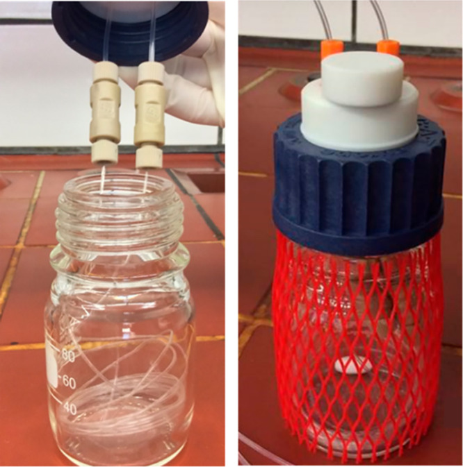
Tube-in-flask setup with the AF-2400 membrane coiled inside a standard flask.
In continuation of our interest in designing generators for larger scales, we established the tube-in-CSTR concept in 2019, which is a fully continuous version of the tube-in-flask reactor.43 By applying the continuous stirred tank reactor (CSTR) cascade depicted in Scheme 11, the three-step synthesis of chiral α-chloroketone 7, as described above, was selected as proof-of-concept study. Compared to the tube-in-tube reactor approach, the productivity of 7 could be increased by a factor of 4.2. For both the tube-in-flask and tube-in-CSTR reactor, in-line FTIR as PAT tool was employed to monitor the reaction process.
In all the above-mentioned CH2N2 generators, Diazald was employed as convenient precursor; however, for a more atom-economic and sustainable route, NMU would be the better choice. By using the semibatch tube-in-flask setup, we also have reported the production of CH2N2 from NMU as precursor, which in turn was generated in situ by nitrosation of N-methylurea in a continuous upstream process.37 The three-step synthesis of α-chloroketone 7 was carried out in one-pot via a similar procedure to that described in Scheme 11.
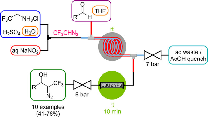
The same tube-in-tube setup as described for CH2N2 was also employed by our group for the generation of trifluoromethyl diazomethane (CF3CHN2),44 which represents a versatile CF3 source that has been neglected for a long time. Similar to CH2N2, it is a gaseous reagent, which is also attributed to being explosive and potentially toxic and thus poses a severe safety risk in batch processes. CF3CHN2 was generated in 33% yield by diazotation of the corresponding amine hydrochloride with NaNO2 under aqueous acidic conditions inside the membrane tubing (Scheme 12). The diazo compound was then further reacted downstream with aldehydes that were fed into the outer tubing in a DBU-catalyzed aldol-type condensation. For an efficient condensation, a packed-bed reactor with polymer-bound DBU needed to be implemented.
Scheme 12. Anhydrous Trifluoromethyl Diazomethane Generator (Tube-in-Tube Reactor) and Its Use in Aldol-type Condensation with Aldehydes.
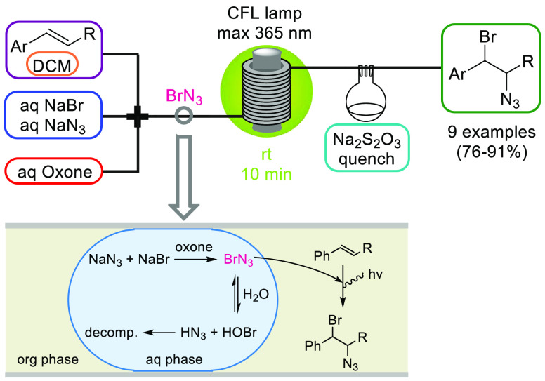
Halogen azides XN3 (X = F, Cl, Br, I) and hydrazoic acid (HN3) are the simplest possible azide compounds. Because of the extreme toxicity and explosive nature of these high-energy materials, their application on lab and even more so on industrial scale is essentially precluded. Bromine azide (BrN3) is exceptionally sensitive to small variations in temperature and pressure and spontaneously explodes under various conditions to generate toxic and corrosive gases. In 2016, we reported the safe generation of BrN3 starting from low-cost NaBr and NaN3 using Oxone as the oxidizing agent and its immediate consumption by an olefin in a radical 1,2-bromoazidation reaction (Scheme 13).45 The segmented flow regime obtained within the tubing and the concomitant rapid extraction of BrN3 from the aqueous into the organic phase was crucial for the process because substantial decomposition of BrN3 in the aqueous phase was prevented (Scheme 13). After an off-line quench with Na2S2O3, the products were isolated by a simple extractive workup and further reacted to aziridines, azirines, and indoles.
Scheme 13. BrN3 Generator with an Integrated Tubular Photochemical Reactor for the Synthesis of 1,2-Bromine Azides.
The continuous in situ generation and consumption of ClN3 and IN3, respectively, was described by the groups of Vögtle and Wirth.46
The first generator concept that was reported by our group in 2010 featured the in situ generation of highly explosive HN3 from inexpensive NaN3 as azide source and acetic acid.47 HN3 was instantly formed upon mixing of the two feeds and then reacted further with organic nitriles (comprised within the acidic feed) in a catalyst-free high-temperature/high-pressure cycloaddition step to furnish 1H-tetrazoles (Scheme 14). As HN3 is not compatible with metals, a passivated silica-coated stainless-steel coil (Sulfinert) was employed as the high-temperature reactor. A throughput of up to 19 g/h was achieved with this atom-economic and cost-effective route toward the tetrazole core, which makes this approach also suitable for industrial scale synthesis.
Scheme 14. HN3 Generator and Its Use in the Synthesis of 5-Substituted 1H-Tetrazoles.

3. From Stable Reagents to Transient Intermediates
The faster the reaction conditions can be changed and the tighter the integration of synthesis, separation, and consumption can be achieved, the more elusive reagents can be prepared. In current state-of-the-art flow reactors, all the above-mentioned steps can be accomplished within seconds or even (sub)-milliseconds.48 Particularly useful for such ultrafast chemistries (flash chemistry) are customized flow reactors and mixing units that can be manufactured from various materials by 3D-printing.49 Such reactors are designed to fit the need for the specific chemistry at hand. Hence, highly transient intermediates with half-lives in the range of milliseconds, such as carbenes or radicals, that only are accessible via their synthesis in situ, can be conveniently generated.48 In this context, our group has recently reported the generation of transient intermediates such as difluorocarbene (:CF2),50 the trifluoromethyl radical (·CF3),51 or bromomethyl lithium.52 The detailed discussion of these highly reactive species is outside the scope of this Account on chemical generators, and the reader is referred to pertinent literature.48
4. Conclusion and Outlook
Continuous flow devices are uniquely suited for carrying out hazardous reactions as they combine low reactor volumes and exceptional heat and mass transport. Furthermore, flow reactor setups can be designed as modular systems that integrate multiple reaction steps, in-line purification procedures, and real-time reaction control employing PAT tools. In this Account, we highlighted various generator concepts for the safe on-site on-demand production of reagents that are too reactive, explosive, toxic, or short-lived to be transported or stored. Importantly, the implementation of such low molecular weight reagents enables the design of the most direct and atom-efficient routes.
Because we are living in challenging times, be it the outbreak of the COVID-19 pandemic or environmental disasters, a rethinking of society needs to be induced with respect to globalization. Any of such events can dramatically disrupt the international supply chains, as we are facing shortages of important APIs at this very moment. To become more independent from foreign third-party services, the localized manufacturing of essential chemical products will become more vital. As a consequence, on-site storage of hazardous chemicals will increase, imposing not only an increased safety risk but also potentially higher costs. Therefore, generating reagents on-site and on-demand in continuous flow from inexpensive and readily available starting materials will be a reasonable solution for a chemical society that is increasingly committed to efficiency, sustainability, and safety.
Biographies
Dr. Doris Dallinger obtained her PhD degree in the group of Prof. Kappe at the University of Graz (Austria) on projects related to microwave chemistry. After postdoctoral research work with a focus on microwave effects and scale-up studies, she joined the Kappe Group at the University of Graz as a Senior Scientist in 2011. Since 2018, she is also Key Researcher at the Research Center Pharmaceutical Engineering GmbH (RCPE). Her research is focused on hazardous chemistry in continuous flow.
Dr. Bernhard Gutmann studied chemistry at the University of Graz, Austria. In 2009 he obtained his diploma in the field of microwave-assisted organic synthesis. He continued with PhD studies in the group of Prof. Kappe on projects related to continuous-flow processing. After receiving his PhD in 2013, he stayed in Graz as a postdoctoral associate and joined the Research Center Pharmaceutical Engineering GmbH (RCPE) as a Senior Researcher. Since 2018, he is a Senior Chemist at Lonza AG in Visp, Switzerland.
Prof. C. Oliver Kappe studied at the University of Graz with Prof. Gert Kollenz. After postdoctoral research with Prof. Curt Wentrup at the University of Queensland and with Prof. Albert Padwa at Emory University, he moved back to the University of Graz in 1996 to start his independent academic career where he was appointed Professor for “Technology of Organic Synthesis” in 2011. His research interests involve continuous flow and sustainable chemistry, API manufacturing, and process intensification technologies. Since 2017, he leads the Center for Continuous Flow Synthesis and Processing (CCFLOW) at RCPE GmbH.
Author Present Address
§ B.G.: Lonza AG, CH-3930 Visp, Switzerland
The CC Flow Project (Austrian Research Promotion Agency FFG No. 862766) is funded through the Austrian COMET Program by the Austrian Federal Ministry of Transport, Innovation and Technology (BMVIT), the Austrian Federal Ministry of Science, Research and Economy (BMWFW), and by the State of Styria (Styrian Funding Agency SFG).
The authors declare no competing financial interest.
References
- Prominent regulatory frameworks include the United Nations Recommendations on the Transport of Dangerous Goods; Transport by air: International Air Transport Association Dangerous Goods Regulations (IATA-DGR); Transport by rail: International Carriage of Dangerous Goods by Rail (RID); Transport by road: European Agreement concerning the International Carriage of Dangerous Goods (ADR), United States: The Code of Federal Regulations 49; Transport by sea: International Maritime Dangerous Goods Code (IMDG Code), European Agreement Concerning the International Carriage of Dangerous Goods by Inland Waterways (ADN).
- a Tremblay J.-F. China increases the pressure on chemical producers. Chem. Eng. News 2017, 95 (39), 13. [Google Scholar]; b Mullin R. Drug chemical makers brace as China cracks down on pollution. Chem. Eng. News 2018, 96 (7), 23. [Google Scholar]
- Anastas P. T.; Hammond D. G.. Inherent Safety at Chemical Sites: Reducing Vulnerability to Accidents and Terrorism Through Green Chemistry; Elsevier, 2015. [Google Scholar]
- a Gutmann B.; Kappe C. O. Forbidden Chemistries Go Flow in API Synthesis. Chim. Oggi/Chem. Today 2015, 33 (3), 18–24. [Google Scholar]; b Gutmann B.; Cantillo D.; Kappe C. O. Continuous-Flow Technology - A Tool for the Safe Manufacturing of Active Pharmaceutical Ingredients. Angew. Chem., Int. Ed. 2015, 54, 6688–6728. 10.1002/anie.201409318. [DOI] [PubMed] [Google Scholar]; c Movsisyan M.; Delbeke E. I. P.; Berton J. K. E. T.; Battilocchio C.; Ley S. V.; Stevens C. V. Taming Hazardous Chemistry by Continuous Flow Technology. Chem. Soc. Rev. 2016, 45, 4892–4928. 10.1039/C5CS00902B. [DOI] [PubMed] [Google Scholar]; d Singh R.; Lee H.-J.; Singh A. K.; Kim D.-P. Recent Advances for Serial Processes of Hazardous Chemicals in Fully Integrated Microfluidic Systems. Korean J. Chem. Eng. 2016, 33, 2253–2267. 10.1007/s11814-016-0114-6. [DOI] [Google Scholar]; e Movsisyan M.; Heugebaert T. S. A.; Stevens C. V. Safely Scaling Hazardous Chemistry through Continuous Flow Technology. Chim. Oggi/Chem. Today 2017, 35 (3), 60–63. [Google Scholar]; f Kockmann N.; Thenée P.; Fleischer-Trebes C.; Laudadio G.; Noël T. Safety Assessment in Development and Operation of Modular Continuous-Flow Processes. React. Chem. Eng. 2017, 2, 258–280. 10.1039/C7RE00021A. [DOI] [Google Scholar]
- Poechlauer P.; Braune S.; Dielemans B.; Kaptein B.; Obermüller R.; Thathagar M. On-Site-on Demand Production of Hazardous Chemicals by Continuous Flow Processes. Chim. Oggi/Chem. Today 2012, 30 (4), 51–54. [Google Scholar]
- a May S. A. Flow Chemistry, Continuous Processing, and Continuous Manufacturing: A Pharmaceutical Perspective. J. Flow Chem. 2017, 7, 137–145. 10.1556/1846.2017.00029. [DOI] [Google Scholar]; b Continuous Manufacturing of Pharmaceuticals; Kleinebudde P., Khinast J., Rantanen J., Eds.; Wiley-VCH: Weinheim, 2017. [Google Scholar]; c Baumann M.; Baxendale I. R. The Synthesis of Active Pharmaceutical Ingredients (APIs) Using Continuous Flow Chemistry. Beilstein J. Org. Chem. 2015, 11, 1194–1219. 10.3762/bjoc.11.134. [DOI] [PMC free article] [PubMed] [Google Scholar]; d Porta R.; Benaglia M.; Puglisi A. Flow Chemistry: Recent Developments in the Synthesis of Pharmaceutical Products. Org. Process Res. Dev. 2016, 20, 2–25. 10.1021/acs.oprd.5b00325. [DOI] [Google Scholar]; e Bogdan A. R.; Dombrowski A. W. Emerging Trends in Flow Chemistry and Applications to the Pharmaceutical Industry. J. Med. Chem. 2019, 62, 6422–6468. 10.1021/acs.jmedchem.8b01760. [DOI] [PubMed] [Google Scholar]; f Baumann M.; Moody T. S.; Smyth M.; Wharry S. A Perspective on Continuous Flow Chemistry in the Pharmaceutical Industry. Org. Process Res. Dev. 2020, 10.1021/acs.oprd.9b00524. [DOI] [Google Scholar]; g Berton M.; de Souza J. M.; Abdiaj I.; McQuade D. T.; Snead D. R. Scaling Continuous API Synthesis from Milligram to Kilogram: Extending the Enabling Benefits of Micro to the Plant. J. Flow Chem. 2020, 10, 73–92. 10.1007/s41981-019-00060-x. [DOI] [Google Scholar]
- Chanda A.; Daly A. M.; Foley D. A.; LaPack M. A.; Mukherjee S.; Orr J. D.; Reid G. L. III; Thompson D. R.; Ward H. W. II Industry Perspectives on Process Analytical Technology: Tools and Applications in API Development. Org. Process Res. Dev. 2015, 19, 63–83. 10.1021/op400358b. [DOI] [Google Scholar]
- a Ley S. V.; Fitzpatrick D. E.; Ingham R. J.; Myers R. M. Organic Synthesis: March of the Machines. Angew. Chem., Int. Ed. 2015, 54, 3449–3464. 10.1002/anie.201410744. [DOI] [PubMed] [Google Scholar]; b Sagmeister P.; Williams J. D.; Hone C. A.; Kappe C. O. Laboratory of the Future: A Modular Flow Platform with Multiple Integrated PAT Tools for Multistep Reactions. React. Chem. Eng. 2019, 4, 1571–1578. 10.1039/C9RE00087A. [DOI] [Google Scholar]
- a Sans V.; Cronin L. Towards Dial-a-Molecule by Integrating Continuous Flow, Analytics and Self-Optimisation. Chem. Soc. Rev. 2016, 45, 2032–2043. 10.1039/C5CS00793C. [DOI] [PMC free article] [PubMed] [Google Scholar]; b Gioiello A.; Piccinno A.; Lozza A. M.; Cerra B. The Medicinal Chemistry in the Era of Machines and Automation: Recent Advances in Continuous Flow Technology. J. Med. Chem. 2020, 10.1021/acs.jmedchem.9b01956. [DOI] [PMC free article] [PubMed] [Google Scholar]
- Sholl D. S.; Lively R. P. Seven Chemical Separations to Change the World. Nature 2016, 532, 435–437. 10.1038/532435a. [DOI] [PubMed] [Google Scholar]
- Adamo A.; Heider P. L.; Weeranoppanant N.; Jensen K. F. Membrane-Based, Liquid–Liquid Separator with Integrated Pressure Control. Ind. Eng. Chem. Res. 2013, 52, 10802–10808. 10.1021/ie401180t. [DOI] [Google Scholar]
- Brzozowski M.; O’Brien M.; Ley S. V.; Polyzos A. Flow Chemistry: Intelligent Processing of Gas–Liquid Transformations Using a Tube-in-Tube Reactor. Acc. Chem. Res. 2015, 48, 349–362. 10.1021/ar500359m. [DOI] [PubMed] [Google Scholar]
- Kumar V. Cyanogen Bromide (CNBr). Synlett 2005, 2005, 1638–1639. 10.1055/s-2005-869872. [DOI] [Google Scholar]
- Glotz G.; Lebl R.; Dallinger D.; Kappe C. O. Integration of Bromine and Cyanogen Bromide Generators for the Continuous-Flow Synthesis of Cyclic Guanidines. Angew. Chem., Int. Ed. 2017, 56, 13786–13789. 10.1002/anie.201708533. [DOI] [PubMed] [Google Scholar]
- Steiner A.; Williams J. D.; de Frutos O.; Rincón J. A.; Mateos C.; Kappe C. O. Continuous Photochemical Benzylic Bromination Using in Situ Generated Br2: Process Intensification towards Optimal PMI and Throughput. Green Chem. 2020, 22, 448–454. 10.1039/C9GC03662H. [DOI] [Google Scholar]
- Van Kerrebroeck R.; Naert P.; Heugebaert T. S. A.; D’hooghe M.; Stevens C. V. Electrophilic Bromination in Flow: A Safe and Sustainable Alternative to the Use of Molecular Bromine in Batch. Molecules 2019, 24, 2116. 10.3390/molecules24112116. [DOI] [PMC free article] [PubMed] [Google Scholar]
- Yu W.; Yu D.; Zheng M.; Shan S.; Li Y.; Gao J. Catalyst and Solvent-Free Bromination of Toluene Derivatives by HBr-H2O2 with Visible-Light Photocatalysis Using a Continuous-Flow Micro Reactor. J. Chem. Res. 2012, 36, 258–260. 10.3184/174751912X13333614619977. [DOI] [Google Scholar]
- Strauss F. J.; Cantillo D.; Guerra J.; Kappe C. O. A Laboratory-Scale Continuous Flow Chlorine Generator for Organic Synthesis. React. Chem. Eng. 2016, 1, 472–476. 10.1039/C6RE00135A. [DOI] [Google Scholar]
- Lebl R.; Cantillo D.; Kappe C. O. Continuous Generation, In-Line Quantification and Utilization of Nitrosyl Chloride in Photonitrosation Reactions. React. Chem. Eng. 2019, 4, 738–746. 10.1039/C8RE00323H. [DOI] [Google Scholar]
- Acke D. R. J.; Stevens C. V. A HCN-Based Reaction under Microreactor Conditions: Industrially Feasible and Continuous Synthesis of 3,4-Diamino-1H-Isochromen-1-Ones. Green Chem. 2007, 9, 386–390. 10.1039/b615186h. [DOI] [Google Scholar]
- Köckinger M.; Hone C. A.; Kappe C. O. HCN on Tap: On-Demand Continuous Production of Anhydrous HCN for Organic Synthesis. Org. Lett. 2019, 21, 5326–5330. 10.1021/acs.orglett.9b01941. [DOI] [PubMed] [Google Scholar]
- Singh A. K.; Ko D.-H.; Vishwakarma N. K.; Jang S.; Min K.-I.; Kim D.-P. Micro-Total Envelope System with Silicon Nanowire Separator for Safe Carcinogenic Chemistry. Nat. Commun. 2016, 7, 10741. 10.1038/ncomms10741. [DOI] [PMC free article] [PubMed] [Google Scholar]
- Chung Leung G. Y.; Ramalingam B.; Loh G.; Chen A. Efficient and Practical Synthesis of Sulfonamides Utilizing SO2 Gas Generated On Demand. Org. Process Res. Dev. 2020, 24, 546–554. 10.1021/acs.oprd.9b00552. [DOI] [Google Scholar]
- Global Phosgene Outlook 2016–2021. https://www.marketresearch.com/Gen-Consulting-Company-v4078/Global-Phosgene-Outlook-10248194/ (accessed April 8, 2020).
- Ajmera S. K.; Losey M. W.; Jensen K. F.; Schmidt M. A. Microfabricated Packed-Bed Reactor for Phosgene Synthesis. AIChE J. 2001, 47, 1639–1647. 10.1002/aic.690470716. [DOI] [Google Scholar]
- Fuse S.; Tanabe N.; Takahashi T. Continuous in Situ Generation and Reaction of Phosgene in a Microflow System. Chem. Commun. 2011, 47, 12661–12663. 10.1039/c1cc15662d. [DOI] [PubMed] [Google Scholar]
- a Gutmann B.; Weigl U.; Cox D. P.; Kappe C. O. Batch- and Continuous-Flow Aerobic Oxidation of 14-Hydroxy Opioids to 1,3-Oxazolidines—A Concise Synthesis of Noroxymorphone. Chem. - Eur. J. 2016, 22, 10393–10398. 10.1002/chem.201601902. [DOI] [PubMed] [Google Scholar]; b Gutmann B.; Cantillo D.; Weigl U.; Cox D. P.; Kappe C. O. Design and Development of Pd-Catalyzed Aerobic N-Demethylation Strategies for the Synthesis of Noroxymorphone in Continuous Flow Mode. Eur. J. Org. Chem. 2017, 2017, 914–927. 10.1002/ejoc.201601453. [DOI] [Google Scholar]
- Mata A.; Cantillo D.; Kappe C. O. An Integrated Continuous-Flow Synthesis of a Key Oxazolidine Intermediate to Noroxymorphone from Naturally Occurring Opioids. Eur. J. Org. Chem. 2017, 2017, 6505–6510. 10.1002/ejoc.201700811. [DOI] [Google Scholar]
- a Ebrahimi F.; Kolehmainen E.; Oinas P.; Hietapelto V.; Turunen I. Production of Unstable Percarboxylic Acids in a Microstructured Reactor. Chem. Eng. J. 2011, 167, 713–717. 10.1016/j.cej.2010.08.091. [DOI] [Google Scholar]; b Ebrahimi F.; Kolehmainen E.; Laari A.; Haario H.; Semenov D.; Turunen I. Determination of Kinetics of Percarboxylic Acids Synthesis in a Microreactor by Mathematical Modeling. Chem. Eng. Sci. 2012, 71, 531–538. 10.1016/j.ces.2011.11.028. [DOI] [Google Scholar]
- Weber B.; Sahli S.. Preparation of Low Impurity Opiates in a Continuous Flow Reactor. WO2011117172A1, 2011.
- a Gustafsson T.; Sörensen H.; Pontén F. Development of a Continuous Flow Scale-Up Approach of Reflux Inhibitor AZD6906. Org. Process Res. Dev. 2012, 16, 925–929. 10.1021/op200340c. [DOI] [Google Scholar]; b Müller S. T. R.; Hokamp T.; Ehrmann S.; Hellier P.; Wirth T. Ethyl Lithiodiazoacetate: Extremely Unstable Intermediate Handled Efficiently in Flow. Chem. - Eur. J. 2016, 22, 11940–11942. 10.1002/chem.201602133. [DOI] [PubMed] [Google Scholar]; c Ganiek M. A.; Becker M. R.; Berionni G.; Zipse H.; Knochel P. Barbier Continuous Flow Preparation and Reactions of Carbamoyllithiums for Nucleophilic Amidation. Chem. - Eur. J. 2017, 23, 10280–10284. 10.1002/chem.201702593. [DOI] [PubMed] [Google Scholar]
- von Keutz T.; Strauss F. J.; Cantillo D.; Kappe C. O. Continuous Flow Multistep Synthesis of α-Functionalized Esters via Lithium Enolate Intermediates. Tetrahedron 2018, 74, 3113–3117. 10.1016/j.tet.2017.11.063. [DOI] [Google Scholar]
- a Doyle M. P.; McKervey M. A.; Ye T.. Modern Catalytic Methods for Organic Synthesis with Diazo Compounds: From Cyclopropanes to Ylides; Wiley: New York, 1998. [Google Scholar]; b Ford A.; Miel H.; Ring A.; Slattery C. N.; Maguire A. R.; McKervey M. A. Modern Organic Synthesis with α-Diazocarbonyl Compounds. Chem. Rev. 2015, 115, 9981–10080. 10.1021/acs.chemrev.5b00121. [DOI] [PubMed] [Google Scholar]
- a Deadman B. J.; Collins S. G.; Maguire A. R. Taming Hazardous Chemistry in Flow: The Continuous Processing of Diazo and Diazonium Compounds. Chem. - Eur. J. 2015, 21, 2298–2308. 10.1002/chem.201404348. [DOI] [PubMed] [Google Scholar]; b Müller S. T. R.; Wirth T. Diazo Compounds in Continuous-Flow Technology. ChemSusChem 2015, 8, 245–250. 10.1002/cssc.201402874. [DOI] [PubMed] [Google Scholar]; c Hock K. J.; Koenigs R. M. The Generation of Diazo Compounds in Continuous-Flow. Chem. - Eur. J. 2018, 24, 10571–10583. 10.1002/chem.201800136. [DOI] [PubMed] [Google Scholar]
- a Maurya R. A.; Min K. I.; Kim D.-P. Continuous Flow Synthesis of Toxic Ethyl Diazoacetate for Utilization in an Integrated Microfluidic System. Green Chem. 2014, 16, 116–120. 10.1039/C3GC41226A. [DOI] [Google Scholar]; b Delville M. M. E.; van Hest J. C. M.; Rutjes F. P. J. T. Ethyl Diazoacetate Synthesis in Flow. Beilstein J. Org. Chem. 2013, 9, 1813–1818. 10.3762/bjoc.9.211. [DOI] [PMC free article] [PubMed] [Google Scholar]
- a Dallinger D.; Kappe C. O. Recent Enabling Technologies for Diazomethane Generation and Reactions. Aldrichimica Acta 2016, 49, 57–66. [Google Scholar]; b Yang H.; Martin B.; Schenkel B. On-Demand Generation and Consumption of Diazomethane in Multistep Continuous Flow Systems. Org. Process Res. Dev. 2018, 22, 446–456. 10.1021/acs.oprd.7b00302. [DOI] [Google Scholar]
- Garbarino S.; Guerra J.; Poechlauer P.; Gutmann B.; Kappe C. O. One-Pot Synthesis of α-Haloketones Employing a Membrane-Based Semibatch Diazomethane Generator. J. Flow Chem. 2016, 6, 211–217. 10.1556/1846.2015.00046. [DOI] [Google Scholar]
- Lehmann H. A Scalable and Safe Continuous Flow Procedure for In-Line Generation of Diazomethane and Its Precursor MNU. Green Chem. 2017, 19, 1449–1453. 10.1039/C6GC03066A. [DOI] [Google Scholar]
- Mastronardi F.; Gutmann B.; Kappe C. O. Continuous Flow Generation and Reactions of Anhydrous Diazomethane Using a Teflon AF-2400 Tube-in-Tube Reactor. Org. Lett. 2013, 15, 5590–5593. 10.1021/ol4027914. [DOI] [PubMed] [Google Scholar]
- Pinho V. D.; Gutmann B.; Miranda L. S. M.; De Souza R. O. M. A.; Kappe C. O. Continuous Flow Synthesis of α-Halo Ketones: Essential Building Blocks of Antiretroviral Agents. J. Org. Chem. 2014, 79, 1555–1562. 10.1021/jo402849z. [DOI] [PubMed] [Google Scholar]
- Pinho V. D.; Gutmann B.; Kappe C. O. Continuous Flow Synthesis of β-Amino Acids from α-Amino Acids via Arndt-Eistert Homologation. RSC Adv. 2014, 4, 37419–37422. 10.1039/C4RA08113G. [DOI] [Google Scholar]
- a Dallinger D.; Pinho V. D.; Gutmann B.; Kappe C. O. Laboratory-Scale Membrane Reactor for the Generation of Anhydrous Diazomethane. J. Org. Chem. 2016, 81, 5814–5823. 10.1021/acs.joc.6b01190. [DOI] [PubMed] [Google Scholar]; b Dallinger D.; Kappe C. O. Lab-Scale Production of Anhydrous Diazomethane Using Membrane Separation Technology. Nat. Protoc. 2017, 12, 2138–2147. 10.1038/nprot.2017.046. [DOI] [PubMed] [Google Scholar]
- Wernik M.; Poechlauer P.; Schmoelzer C.; Dallinger D.; Kappe C. O. Design and Optimization of a Continuous Stirred Tank Reactor Cascade for Membrane-Based Diazomethane Production: Synthesis of α-Chloroketones. Org. Process Res. Dev. 2019, 23, 1359–1368. 10.1021/acs.oprd.9b00115. [DOI] [Google Scholar]
- Pieber B.; Kappe C. O. Generation and Synthetic Application of Trifluoromethyl Diazomethane Utilizing Continuous Flow Technologies. Org. Lett. 2016, 18, 1076–1079. 10.1021/acs.orglett.6b00194. [DOI] [PubMed] [Google Scholar]
- Cantillo D.; Gutmann B.; Kappe C. O. Safe Generation and Use of Bromine Azide under Continuous Flow Conditions-Selective 1,2-Bromoazidation of Olefins. Org. Biomol. Chem. 2016, 14, 853–857. 10.1039/C5OB02425K. [DOI] [PubMed] [Google Scholar]
- a Leforestier B.; Vögtle M. Safe Generation and Direct Use of Chlorine Azide in Flow Chemistry: 1,2-Azidochlorination of Olefins and Access to Triazoles. Synlett 2016, 27, 1957–1962. 10.1055/s-0035-1561659. [DOI] [Google Scholar]; b Brandt J. C.; Wirth T.. Controlling Hazardous Chemicals in Microreactors: Synthesis with Iodine Azide. Beilstein J. Org. Chem. 2009, 5 10.3762/bjoc.5.30. [DOI] [PMC free article] [PubMed] [Google Scholar]
- Gutmann B.; Roduit J.-P.; Roberge D.; Kappe C. O. Synthesis of 5-Substituted 1H-Tetrazoles from Nitriles and Hydrazoic Acid by Using a Safe and Scalable High-Temperature Microreactor Approach. Angew. Chem., Int. Ed. 2010, 49, 7101–7105. 10.1002/anie.201003733. [DOI] [PubMed] [Google Scholar]
- a Yoshida J.-i.; Nagaki A.; Yamada T. Flash Chemistry: Fast Chemical Synthesis by Using Microreactors. Chem. - Eur. J. 2008, 14, 7450–7459. 10.1002/chem.200800582. [DOI] [PubMed] [Google Scholar]; b Yoshida J.-i.; Takahashi Y.; Nagaki A. Flash Chemistry: Flow Chemistry That Cannot Be Done in Batch. Chem. Commun. 2013, 49, 9896–9904. 10.1039/C3CC44709J. [DOI] [PubMed] [Google Scholar]; c Kim H.; Min K.-I.; Inoue K.; Im D. J.; Kim D.-P.; Yoshida J.-i. Submillisecond Organic Synthesis: Outpacing Fries Rearrangement through Microfluidic Rapid Mixing. Science 2016, 352, 691–694. 10.1126/science.aaf1389. [DOI] [PubMed] [Google Scholar]
- Ko D.-H.; Gyak K.-W.; Kim D.-P. Emerging Microreaction Systems Based on 3D Printing Techniques and Separation Technologies. J. Flow Chem. 2017, 7, 72–81. 10.1556/1846.2017.00013. [DOI] [Google Scholar]
- a Gutmann B.; Köckinger M.; Glotz G.; Ciaglia T.; Slama E.; Zadravec M.; Pfanner S.; Maier M. C.; Gruber-Wölfler H.; Kappe C. O. Design and 3D Printing of a Stainless Steel Reactor for Continuous Difluoromethylations Using Fluoroform. React. Chem. Eng. 2017, 2, 919–927. 10.1039/C7RE00176B. [DOI] [Google Scholar]; b Köckinger M.; Hone C. A.; Gutmann B.; Hanselmann P.; Bersier M.; Torvisco A.; Kappe C. O. Scalable Continuous Flow Process for the Synthesis of Eflornithine Using Fluoroform as Difluoromethyl Source. Org. Process Res. Dev. 2018, 22, 1553–1563. 10.1021/acs.oprd.8b00318. [DOI] [Google Scholar]
- Monteiro J. L.; Carneiro P. F.; Elsner P.; Roberge D. M.; Wuts P. G. M.; Kurjan K. C.; Gutmann B.; Kappe C. O. Continuous Flow Homolytic Aromatic Substitution with Electrophilic Radicals: A Fast and Scalable Protocol for Trifluoromethylation. Chem. - Eur. J. 2017, 23, 176–186. 10.1002/chem.201604579. [DOI] [PubMed] [Google Scholar]
- von Keutz T.; Cantillo D.; Kappe C. O. Continuous Flow Synthesis of Terminal Epoxides from Ketones using In Situ Generated Bromomethyl Lithium. Org. Lett. 2019, 21, 10094–10098. 10.1021/acs.orglett.9b04072. [DOI] [PubMed] [Google Scholar]


