Abstract
In space plasma, various effects of magnetic reconnection and turbulence cause the electron motion to significantly deviate from their Larmor orbits. Collectively these orbits affect the electron velocity distribution function and lead to the appearance of the “non-gyrotropic” elements in the pressure tensor. Quantification of this effect has important applications in space and laboratory plasma, one of which is tracing the electron diffusion region (EDR) of magnetic reconnection in space observations. Three different measures of agyrotropy of pressure tensor have previously been proposed, namely, A∅e, Dng and Q. The multitude of contradictory measures has caused confusion within the community. We revisit the problem by considering the basic properties an agyrotropy measure should have. We show that A∅e, Dng and Q are all defined based on the sum of the principle minors (i.e. the rotation invariant I2) of the pressure tensor. We discuss in detail the problems of I2-based measures and explain why they may produce ambiguous and biased results. We introduce a new measure AG constructed based on the determinant of the pressure tensor (i.e. the rotation invariant I3) which does not suffer from the problems of I2-based measures. We compare AG with other measures in 2 and 3-dimension particle-in-cell magnetic reconnection simulations, and show that AG can effectively trace the EDR of reconnection in both Harris and force-free current sheets. On the other hand, A∅e does not show prominent peaks in the EDR and part of the separatrix in the force-free reconnection simulations, demonstrating that A∅e does not measure all the non-gyrotropic effects in this case, and is not suitable for studying magnetic reconnection in more general situations other than Harris sheet reconnection.
I. INTRODUCTION
The pressure tensor in kinetic theory1 is defined as:
| (1) |
where vi and vj are the ith and jth components of the velocity of a particle and represent the mean velocity of particles. In fluid dynamics the pressure tensor corresponds to the negative of the stress tensor, but the definition of pressure tensor is more general and does not depend on the validity of the fluid description of plasma. Pressure tensor is real, symmetric, i.e. Pij = Pji, and positive semidefinite. In homogeneous and isotropic plasma, pressure tensor becomes Pij = Pδij and is reduced to a scalar. The isotropy can be broken in the presence of a magnetic field. The motion of charged particles and hence their macroscopic properties may be very different in directions parallel and perpendicular to the magnetic field. In most situations encountered in space and laboratory plasma, charged particles are magnetized, i.e., their gyro-radii being much smaller than the variation scale of the magnetic field, hence their motion can be approximated by the fast cyclotron motion plus a drift. We call such motion Larmor. Magnetized plasma usually relaxes independently in directions parallel and perpendicular to the magnetic field, and consequently the velocity distribution function assumes an axisymmetric form, i.e. f(v) = f(v‖, v⊥). The pressure tensor is also axisymmetric in the geometric representation2, i.e., having one principle axis of the pressure tensor aligned with the magnetic field as shown in Fig. 1. The “gyrotropic” pressure tensor with independent P‖ and P⊥ can be written as
| (2) |
FIG. 1.
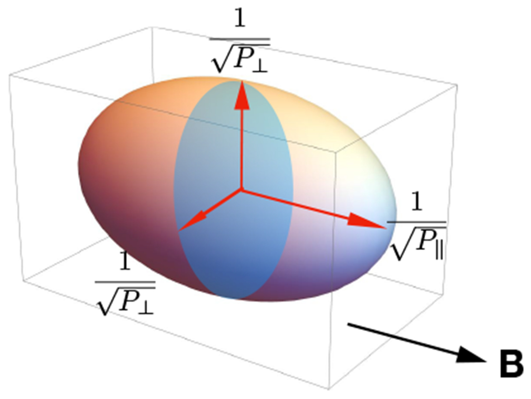
The ellipsoid of a gyrotropic pressure tensor in its principle coordinate with one axis parallel to the local magnetic field. The lengths of the three axes of the ellipsoid are and .
In some important phenomena such as magnetic reconnection in current sheets and turbulence, charged particles encounter large spatial variations of magnetic field or fast changing external forces, and their orbits become far more complicated3 than the Larmor orbits in uniform or quasi-uniform magnetic fields. These particles can transport momentum between different directions, the collective motion of particles lead to the breaking the axisymmetry or gyrotropy of the distribution function.
The simplest manifestation of gyrotropy breaking in pressure tensor is when the perpendicular part of the pressure breaks axisymmetry, but one principle axis of the pressure tensor remains along the magnetic field, thus can be written as:
| (3) |
where P⊥1 ≠ P⊥2 and the description of pressure tensor needs three independent parameters. In general the non-Larmor motion of particles can lead the non-diagonal elements of pressure in Eq. (3) to become non-zero, and in geometric terms none of principle axes are aligned with the magnetic field:
| (4) |
Non-Larmor motion of charged particles can occur in regions with strong inhomogeneity and large shear. A simple example can be found around current density peaks in thin current sheets where the magnetic field reverses its direction5. In this type of current sheet the magnetic shear is large while the field is weak, a condition that causes the electrons to demagnetize and their orbits are characterized by the so called meandering motion. In an unperturbed (static) current layer with magnetic field configuration shown in Fig. 2, the components of the non-relativistic canonical momentum p of an electron are:
| (5) |
FIG. 2.
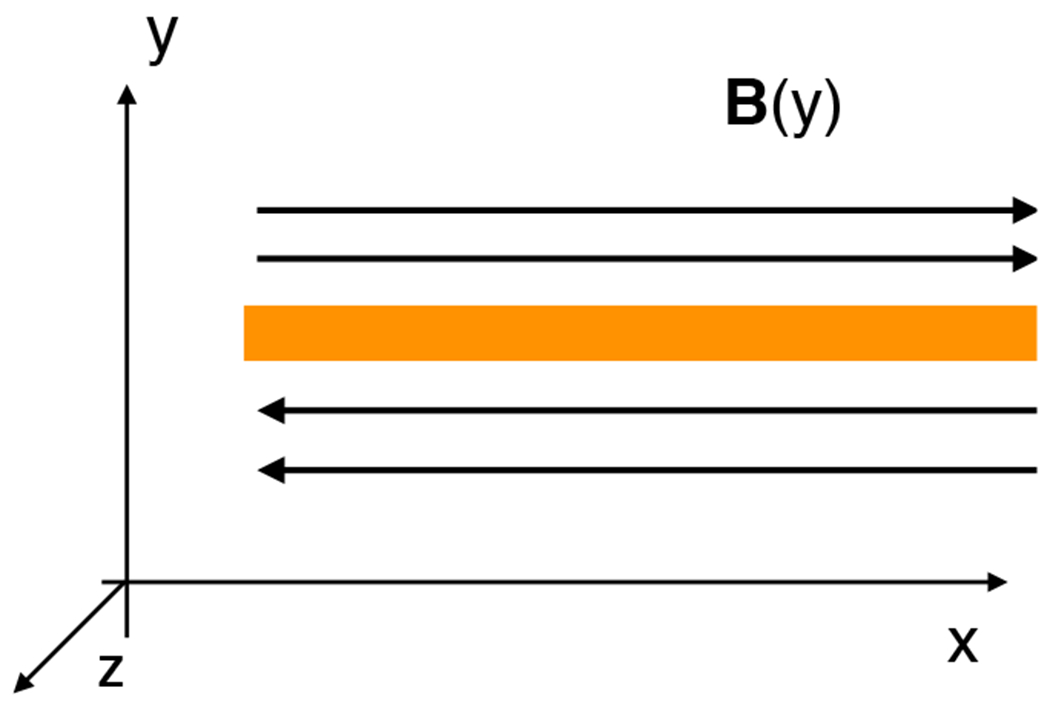
An Illustration of current sheet.
with A being the magnetic vector potential, and the Hamiltonian is . The energy of the electron is conserved. The Hamiltonian equations ∂pi/∂t = −∂H/∂xi = 0 imply that in a static anti-parallel magnetic field, each component of canonical momentum is also conserved. As electrons move near or cross the magnetic null, the sharp change of magnetic field Bx = ∂yAz(y) leads to inhomogeneous drift and meandering motion of particles in the yz directions6. A consequence of the conservation of canonical momentum and energy is that the change in magnetic momentum is redistributed between the kinetic momentum mvy and mvz. Collectively the effect causes the electron velocity distribution function to deviate from Maxwellian in directions perpendicular to the magnetic field. The consequence is the nondiagnal elements of the pressure tensor in a field-aligned frame generally become nonzero or the perpendicular elements becomes unequal. An initially gyrotropic pressure tensor eventually becomes
| (6) |
in any field aligned coordinate except in the eigenvector aligned frame, i.e., a frame determined by the magnetic field and the current sheet normal, where the pressure tensor become diagonalized to the form shown in Eq. (3). It should be noted that the commonly used Harris solution7 of Vlasov equation is obtained under the assumption of global isotropic pressure despite the existence of local meandering motions near the null region. If an out-of-plane electric field exists, the chaotic motions of electrons around null-point become more complex and can produce dramatic non-gyrotropic effects which play an important role in magnetic reconnection4,8.
In magnetic reconnection, the situation is more complex than in current sheets associated with anti-parallel magnetic fields. First, the topological change of the magnetic field can break the 2D anti-parallel magnetic field configuration which produces sharply curved field lines and reconnection electric field. In component reconnection, the magnetic field is 3D. The magnetic vector potential is no longer dependent only on the two spatial coordinates perpendicular to the magnetic field. Consequently the Hamiltonian of particles also become functions of all canonical coordinates and no component of canonical momentum is guaranteed to conserve, i.e., ∂pi/∂t = 09,10. More importantly, the motion of particles around the reconnection x-line can become stochastic11–14. Such stochastic motion causes diffusion in the velocity space and allows the particles to transfer kinetic momentum between different directions and build up correlations between all velocity components15. On the other hand, kinetic instabilities are common in magnetic reconnection and these instabilities can also produce anisotropic heating and scattering. Electron-scale magnetic reconnection configurations can be produced in turbulence due to anomalous dissipation of magnetic energy16. Considering all these complexities, in magnetic reconnection the non-diagonal elements of the pressure tensor in the field-aligned frames are usually non-zero as shown in Eq. (4), and the principle axis of the pressure tensor also is generally not aligned with magnetic field.
In space physics, the interest in the non-Larmor effects on pressure tensor originated from an early argument made by Vasyliunas6 that the gradient of non-gyrotropic part of the electron pressure tensor is essential in supporting the reconnection electric field in 2D static collisionless magnetic reconnection. This effect has since been demonstrated in many Harris sheet magnetic reconnection simulations17–21. It was then suggested22,23 that this effect may be used to “illuminate” the electron diffusion region (EDR) of magnetic reconnection in in-situ observations of the magnetosphere, given that other indicators of the EDR are not ubiquitous. In nature, magnetic reconnections generally are not 2D and static, and the pressure gradient is not necessarily the only or the dominant term in the Ohm’s law that supports the reconnection electric field. Nevertheless, the singular magnetic field configuration at the vicinity of the x-line is sufficient to produces significant amount of non-Larmor electrons in the EDR3,11–13. Therefore, the effect of the non-Larmor electrons on the pressure tensor should be significant in most of the reconnection events, not just in 2D simulations, and should be a useful indicator of the EDR.
In practice, quantification of the non-Larmor effect provides a useful parameter for detection of crossings of the EDR in the time sequence data obtained by space probes, e.g. the recently launched Magnetospheric Multiscale Science (MMS)24. While the electron velocity distribution functions carry detailed information of the statistical properties of the electrons, a quantification of the effects of agyrotropy on the pressure tensor allows easy comparison of observations at different locations and time from space instruments. Such a quantity is particularly convenient when searching for magnetic reconnection EDRs in large observation datasets, or conducting correlation analysis of pressure tensor and other thermodynamic or electromagnetic properties of plasma.
Several measures of agyrotropy of pressure tensor have previously been proposed. An early proposal22 defines agyrotropy as the relative difference of the two eigenvalues of the perpendicular sub-matrix of the pressure tensor in the field aligned coordinate, i.e. (We ignored the factor of 2 in the original definition.) . In other words, after a rotation around the magnetic field , here is the 2D space rotation matrix, the pressure tensor in Eq.(4) becomes
| (7) |
where ′ represents the new values after the rotation. The definition A∅e is criticized for not accounting for the contribution from all the non-diagonal components of the pressure tensor25. A∅e is clearly defined assuming the deformation of electron orbits only occurs in the perpendicular directions and the momentum transport is constrained to the perpendicular plane (which is not generally the case). In this particular situation the pressure tensor is always field aligned and the definition of agyrotropy as A∅e is an intuitive choice. In situations where the deformations of the electron orbits are not confined to the perpendicular directions, as demonstrated in magnetic reconnection simulations3,11–13, A∅e clearly misses contributions from orbit distortions that are not confined to the perpendicular plane. To make A∅e useful, the proponents of A∅e have to hope that the distortion of electron orbits in the perpendicular plane always dominates so that A∅e can still be used as a biased tracer of the EDR. This is a falsifiable proposition, and all we need is an example to show that non-gyrotropic effect can be strong but A∅e is small, as we will do in § IID.
Albeit different measures have been proposed, it is generally agreed that agyrotropy is a scalar that quantifies the departure of the pressure tensor from axisymmetry about the local magnetic field. Mathematically, any pressure tensor can be written in the following form in the field-aligned coordinate:
| (8) |
this pressure tensor can be uniquely decomposed into a gyrotropic part in the form of Eq. (2) and a nongyrotropic part
| (9) |
such that .
Using this decomposition, Aunai et. al.25 proposed an agyrotropy measure
| (10) |
An alternative is proposed by Swisdak26 as:
| (11) |
Ignoring the numeric factor, the numerator of and Q are the same, but in Dng the denominator is the trace of the pressure tensor while in Q it is a quadratic function of the diagonal elements.
The contradicting definitions of non-gyrotropy/agyrotrpy measure has caused confusion and naturally raised the question of how arbitrary one can define agyrotropy: should the freedom of choice limited by some physical and mathematical principles? What is a good measure of agyrotropy? These are the issues we intend to address in this paper. While this study is motivated by in situ observations of the magnetic reconnection in the magnetosphere, the subject has much broader applications in plasma physics, such as turbulence in which microscopic reconnection is thought to be important. It is not the purpose of this paper to discuss if a certain method may work in specific observations or conditions.
We first consider the basic properties a good measure of agyrotropy should have, and based on these considerations we propose a new independent non-gyrotropic measure AG. We then examine AG and re-examine the non-gyrotropic measures previously proposed, namely, A∅e, Dng, and Q in cases of different magnetic field alignments. We find that only AG is well-behaved in all these cases. As a demonstration of the method, we examine and compare AG, Q, Dng and A∅e in particle-in-cell simulations of magnetic reconnection. Space observations have shown that turbulence is very important in magnetic reconnection27–29, but its influence on agyrotropy has not been investigated previously. We analyze both turbulent and non-turbulent magnetic reconnection simulations with both force-free and Harris current sheets. We find that A∅e can not properly trace the EDR and turbulent current broadening effect in force-free magnetic reconnection.
II. MEASURING AGYROTROPY
A. Basic Considerations
Measurement of any quantity generally involves comparison with some precisely defined unit value of the quantity. The definition should be unique and reflect the property investigated. Applying these basic principles to agyrotropy – a derived quantity from pressure tensor, we must first define a quantity that describes gyrotropy, then the departure from this quantity is the measure of agyrotropy.
We hence consider the following basic requirements for a scalar measure of agyrotropy in pressure: (a) The gyrotropic pressure should be uniquely defined for any given pressure tensor. Since the decomposition of into and is unique25, is the unique gyrotropic tensor associated with ; (b) The function that maps to a scalar, i.e., should be the same function that operates on so that measures the departure from gyrotropy; Note that F is not required to be a linear function of pressure tensor, and in general . (c) Because gyrotropy depends on the direction of local magnetic field, the scalar agyrotropy measure should reflect this dependence; (d) While the representation of pressure tensor depends on the choice of orthogonal coordinate base , i.e. , where i, j = 1,2,3, the scalar function F should not depend on a specific coordinate system in which P and G are measured, so that the agyrotropy measure is coordinate independent. The obvious choices for such scalar operators that satisfies (b) in any coordinate are invariants under spatial rotation.
Based on these basic considerations, we can construct a scalar measure of agyrotropy. The simplest way to define a coordinate independent scalar operator is to use the rotational invariants of pressure tensor . Mathematically there are only three such invariants: the trace I1, the sum of principle minors I2, and the determinant I3, i.e.,
| (12) |
| (13) |
| (14) |
It is obvious that I1 alone cannot be used to construct an agyrotropy measure since does not satisfy (a)–(c). I2, I3 are two possible independent choices. We first introduce a new agyrotropic measure AG based on I3, and then revisit the previously defined agyrotropy measures A∅e, Dng and Q and compare them with AG.
B. A New Measure of agyrotropy
From the discussions above we see that it is possible to define a measure of agyrotropy based on the invariant I3. By definition depends on the local magnetic field, and obviously satisfies (c) and (d). In addition, is also unique in that it has the largest determinant among pressure tensors with the same diagonal elements. This is because:
| (15) |
where we used the pressure tensor defined in Eq. (8). Since the principle minor of positive semidefinite requires P⊥ ≥ Pc, the departure .
In theory the absolute departure is sufficient to describe agyrotropy for a specific . In practice we need to compare agyrotropy for different at different locations, or with simulations, and a measure of relative rather than the absolute departure is more useful. It is also desirable to have the relative agyrotropy to have values between 0 and 1. Thus we define the normalized agyrotropy as
| (16) |
When one principle axis of is along the local magnetic field and , then is gyrotropic, and AG = 0. When none the principle axes of is aligned with the local magnetic field, and the eigenvalues are small, then , AG → 1. An example is given by Swisdak26 for extreme agyrotropy limit when the principle axis is not aligned with magnetic field (with one or two eigenvalues being 0)
| (17) |
with x > 0. The eigenvalues are 0,0 and x + 2. In this case and the agyrotropy measure AG = 1.
When the pressure is field aligned, i.e, with one principle axis aligned with the magnetic field and the pressure tensor is in the form of Eq. (3), agyrotropy should depend only on the perpendicular components of the pressure because the deformation of electron orbits in such cases occur only in the perpendicular plane, limiting the momentum transport in perpendicular directions. Indeed, in this case, AG becomes
| (18) |
which is independent of P‖.
In practice, we can also normalize agyrotropy to the range of [0,∞). In this case, agyrotropy can be defined as
| (19) |
where . For extreme agyrotropy, AG′ = ∞ due to . For gyrotropy, and AG′ = 0. If the Pressure has a principle axis aligned with the magnetic field, then AG′ = (P⊥1 − P⊥2)2/(P⊥1P⊥2), also independent of P‖.
C. Revisiting Q, Dng and A∅e
As we have discussed in the preceding section, the invariant may also be used to define a measure of agyrotropy thus that the absolute departure from gyrotropy is . It is easy to show
| (20) |
where we used and . The absolute departure defined in Eq.(20) is a monotonic function of Pa, Pb and Pc. One way to normalize this measure is simply to divide the absolute departure by the sum of and . Since , the ratio is zero, i.e. gyrotropy, if . If , for extreme agyrotropy limit shown in Eq. (17), the maximum of the ratio is 1/3, therefore a factor of 3 is needed to “scale” this definition to [0, 1]. Another way to normalize is dividing it by , which yields the agyrotropy measure Q first proposed by Swisdak26:
where . Since the principle minors of positive semidefinite requires , we have Q ≤ 1. Replacing P⊥ by in , we obtain , and hence the expression in Swisdak (2016)26:
| (21) |
Thus we have shown that Q is in fact a I2-based measure.
When the pressure is field aligned, Q becomes
which is dependent on P‖, a property that is not desirable. When P‖ ≫ P⊥, Q → 0 regardless of the value of P⊥1/P⊥2. This causes ambiguity, particularly between extreme agyrotropy where P⊥1/P⊥2 ≈ 0 or P⊥2/P⊥1 ≈ 0, and gyrotropy. We find this to be a generic problem for the relative agyrotropy measures defined by I2 since in the numerator is independent of P‖, while the denominators – or or their combinations, are all dependent on P‖. Since P‖ in general is not constant and varies with location, the spatial scaling of Q is consequently not uniform in space. In Fig. 3 different agyrotropy measures of field aligned pressure tensors are shown as functions of P⊥1/P⊥2 between 0 to 1. While A∅e and AG have the correct value of 1 for extreme agyrotropy, i.e, P⊥1/P⊥2 = 0, Q and Dng clearly decrease with the value of P‖/P⊥, and in both cases shown they are much smaller than 1. Let P⊥1 = 0, P⊥2 = x and P‖ = αx, where x > 0 and α > 1, we have Q(P⊥1/P⊥2 = 0) = 0.25/α. When α ≫ 1, we have Q → 0. This completely mixes up agyrotropy with gyrotropy.
FIG. 3.
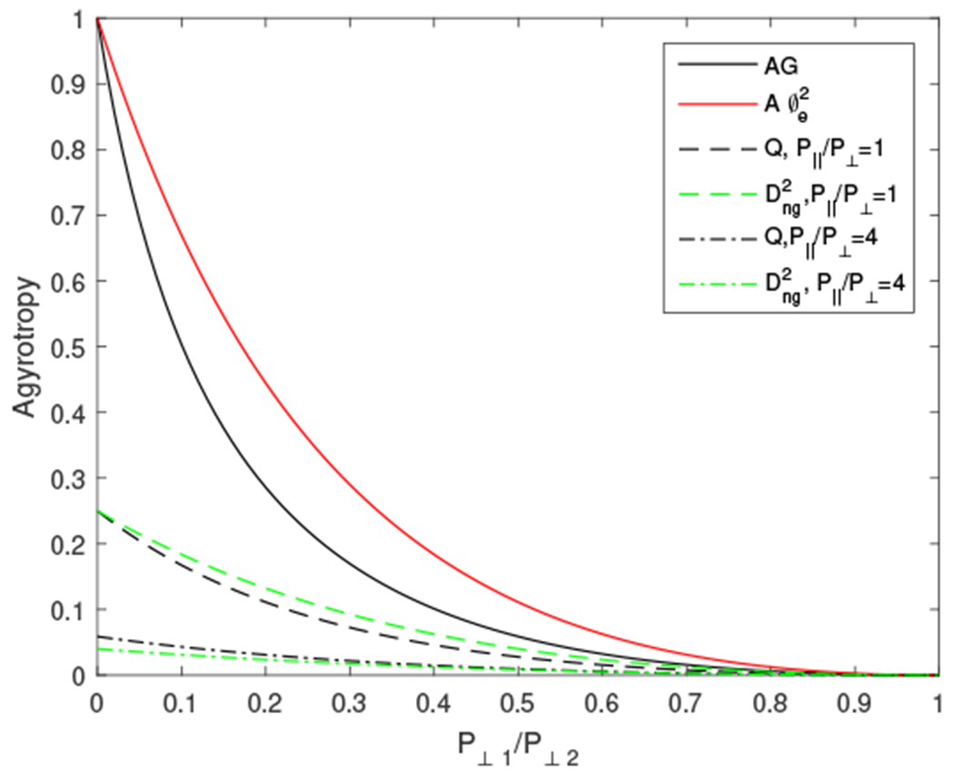
agyrotropy measures as a function of P⊥1/P⊥2 when one principle axis of is aligned with magnetic field. AG (black solid line) and A∅e (red solid line) are independent of P‖ while Q and Dng show strong dependence on P‖.
Now we look at Dng. From the definition , we have given that . It is clear that Dng is also I2 based like Q, except that it is normalized by . By this definition Dng is not strictly a measure of relative departure from gyrotropy. Similar to Q (see Fig.3), Dng also depends on P‖ when the pressure is field aligned, i.e.,
| (22) |
causing unwanted ambiguity. Using I1 as normalization in fact also cause problem in cases when the pressure tensor is not field aligned. To illustrate this point, let us consider the maximum value of Dng. Since being positive semidefinite requires , we have . We can see that instead of being a constant, the maximum value of Dng is a function of P‖ and P⊥, but these two values are spatial functions. This means the scaling of Dng at different locations is not uniform and is also a spatial function, rendering it difficult to have meaningful comparison of agyrotropic effect at different locations when the magnetic field and plasma are nonuniform.
A∅e is defined in a special coordinate formed by the local magnetic field and the two eigenvectors of the perpendicular part of the pressure tensor, and the measure is independent of and in Eq. (7). According to the definition of A∅e, tensor
| (23) |
is gyrotropic, i.e. A∅e = 0. In other words, gyrotropy corresponds to an infinite set (or equivalent class) of tensors with the same diagonal elements, thus the definition contradicts the commonly accepted notion of gyrotropy tensor. In the geometrical representation of the pressure tensor (with Pa ≠ 0 and Pb ≠ 0) corresponds to an ellipsoid whose principle axes tip away from the magnetic field, as shown in Fig. 4. Such pressure tensors are clearly non-gyrotropic. A∅e = 0 simply defines a class of pressure ellipsoids whose cross sections perpendicular to the magnetic field are circular. Thus the definition of A∅e can not distinguish agyrotropic from real gyrotropic .
FIG. 4.
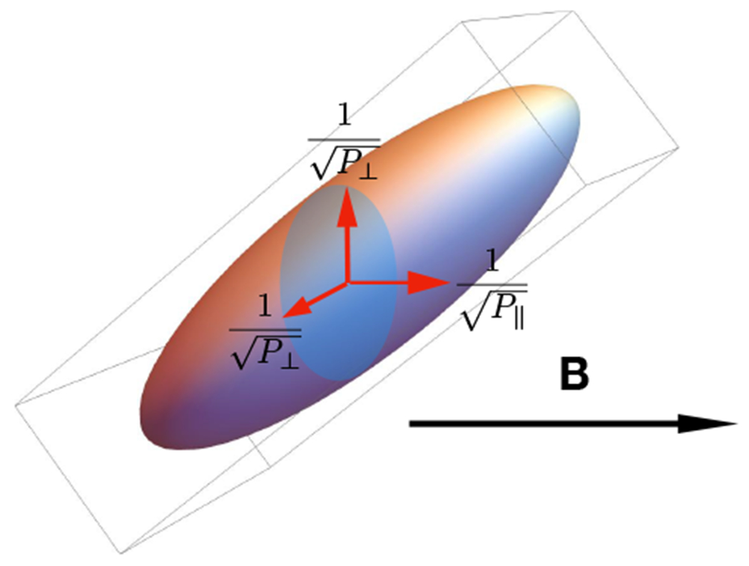
The ellipsoid of agyrotropic pressure tensor in a magnetic field aligned coordinate showing the principle axes of the ellipsoid tipping away from the magnetic field. Since the two perpendicular pressure component are equal, this tensor is considered under the definition A∅e.
We further examine the condition for A∅e = 0 to approximately correspond to gyrotropy. Without losing generality, we assume the principle axes of the pressure ellipse only tip away from the magnetic field in the xy-plane in the magnetic field-aligned coordinate as shown in Fig. 4. Then the axes of the ellipsoid can be found as
We can see that only when for |P‖ – P⊥| ≫ 0, or for P‖ ~ P⊥, reduces to the usual gyrotropic tensor. However, satisfying these conditions are not guaranteed in processes such as magnetic reconnection; and in such cases A∅e = 0 does not define gyrotropy correctly and would miss important contributions from electrons whose orbits are not deformed only in the perpendicular plane. Thus A∅e in general is not a good agyrotropic measure.
The definition of A∅e is not constructed with any of the three rotational invariants in mind, and is more intuitive than other measures that applies to unconstrained pressure tensors. However, it is easy to show that A∅e is actually an I2-based construction. In fact, the I2-based agyrotropy measure Q is reduced to A∅e (ignoring the factor of 2 from the original definition) when P‖ = 0. In other words, A∅e is a degenerate case of Q when P‖ can be ignored.
D. Comparison of AG, Q, Dng and A∅e in Simulations of Magnetic Reconnection
In this section we analyze three particle-in-cell (PIC) simulations performed with the p3d code30 to compare how well AG, Q, Dng and A∅e can track or “illuminate” electron diffusion structures of magnetic reconnection. We demonstrate in these simulations that AG is a robust indicator of the EDR. Q and Dng also appear to track the EDR reasonably well, because while Q and Dng are biased measures of agyrotropy, they only fail catastrophically under extreme conditions that are not met in these simulations. On the other hand, A∅e peaks well outside the EDR in both 2D and 3D force-free magnetic reconnection simulations, thus the simulations provide a concrete example to show that A∅e should not be used as an EDR indicator as it was originally intended.
Comparisons of different agyrotropy measures using magnetic reconnection simulations with Harris current sheet has been made previously26. In the following we only use a 2D Harris current sheet reconnection simulation to demonstrate the performance of AG. The domain size of the simulation is 16di × 8di, where di = c/ωpi,0 is the ion inertial length, and ωpi,0 = (4πn0e2/mi)1/2. In Fig 5, we show AG and Q in the Harris current sheet reconnection. It is not surprising that both measures trace the EDR in a similar fashion. The value of Q is smaller than AG due to the effect of P‖ which we found to be larger than the perpendicular components of the pressure tensor. In Fig. 6, A∅e behaves similarly to AG1/3 (We compare AG1/3 with A∅e because the two quantities have similar values in Harris current sheet thus offer better visual comparison). In the previous studies, it is found that A∅e behaves similarly to Q1/2 in Harris current sheet magnetic reconnection simulations with or without guide field26. This is because Harris current sheet reconnection is essentially a 2D configuration even with a uniform guide magnetic field, and in non-turbulent Harris current sheet reconnection A∅e can behave relatively well in tracing current sheet and diffusion regions26. Dng also can track these structures.
FIG. 5.
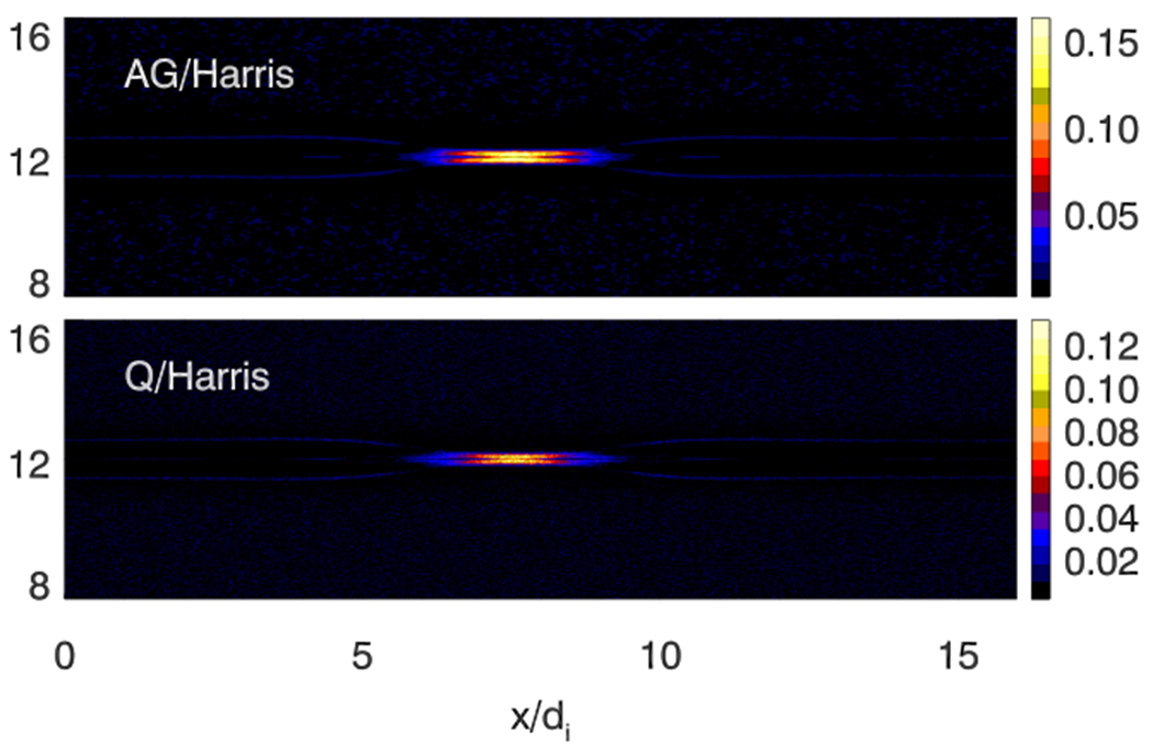
AG and Q in Harris current sheet magnetic reconnection. Both have values significantly higher in the EDR than elsewhere, but the values of Q are generally smaller than AG.
FIG. 6.
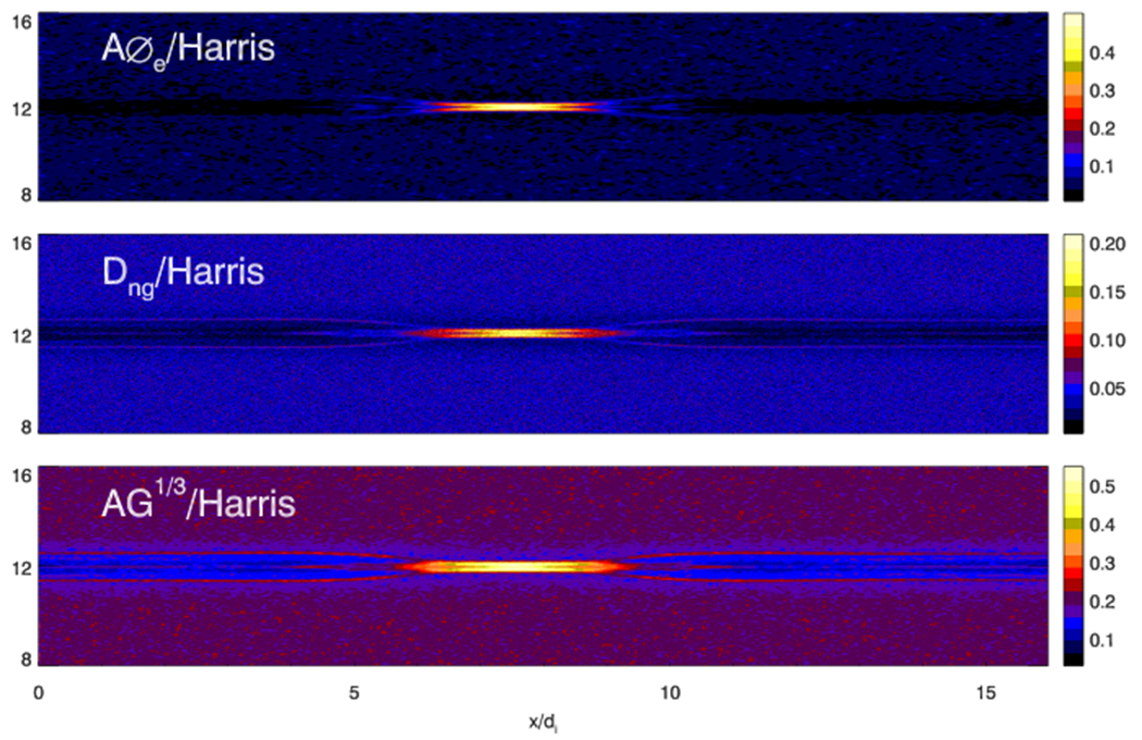
AG1/3 and A∅e in Harris current sheet magnetic reconnection. Both quantities clearly illuminate the EDR.
The initializations of the pair of force-free current sheet reconnection simulations are the same except that one is in 2D while the other in 3D. In the 3D simulation, strong turbulence around the x-line develops at the late stage due to the nonlinear growth of Buneman instability, while in the 2D simulation turbulence cannot develop because the Buneman instability only grows in the direction perpendicular to the reconnection plane. The domain size for the 2D simulation is 4di × 2di while the 3D simulation domain is 4di × 2di × 8di. The simulation time is presented in the unit of ion cyclotron time , and n0 and B0 are the asymptotic density and magnetic field. The guide field is Bg = 5B0. Both simulations have total simulation time Ωi0t = 4. The small box simulations can demonstrate clearly the structure of the EDR. The detailed analysis of these simulations can be found in previous publications31,32.
Force-free current sheet reconnection intrinsically is a 3D configuration in which nonuniform guide magnetic field is the largest at the current sheet. Moreover, turbulence can also cause more complex non-Larmor electron orbits. Whether the measurement can catch the turbulence effects is an important factor to evaluate the robustness of the method to measure agyrotropy. In Fig.7, the out of plane electron current density jez at Ωi0t = 4 from both the 2D and 3D magnetic reconnection simulations are shown. The current sheet in the 3D magnetic reconnection is much broader than that in the 2D magnetic reconnection due to the turbulence scattering32. We also show both AG and Q in the 2D and 3D simulations in Fig. 7. The values of Q and AG are relatively small and Q behaves very similarly to AG. Both AG and Q reach their maxima around the x-line and show two peaks. In the 2D simulation, the EDR is short in the x-direction and is very narrow with dimensions Δx × Δy ≈ 0.5di × 0.1di. In the 3D simulation, the EDR becomes longer and broader with Δx × Δy ≈ 1di × 0.5di.
FIG. 7.
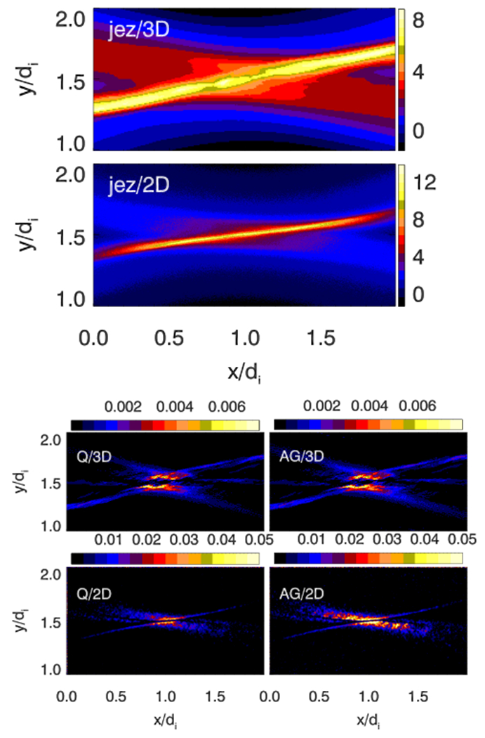
Electron currents and agyrotropy measures in the 2D and 3D simulations of force-free magnetic reconnection with a strong guide field (§IID). Top panels: the out-of-plane current density jez at Ωi0t = 4. Bottom panels: AG and Q at Ωi0t = 4.
In Fig. 8, Dng appear similar to AG1/3 as expected. On the other hand, A∅e peaks well outside the EDR, thus clearly misses the EDR and part of the separatrix in both 2D and 3D force-free reconnection simulations. This makes A∅e an ineffective indicator of the EDR.
FIG. 8.
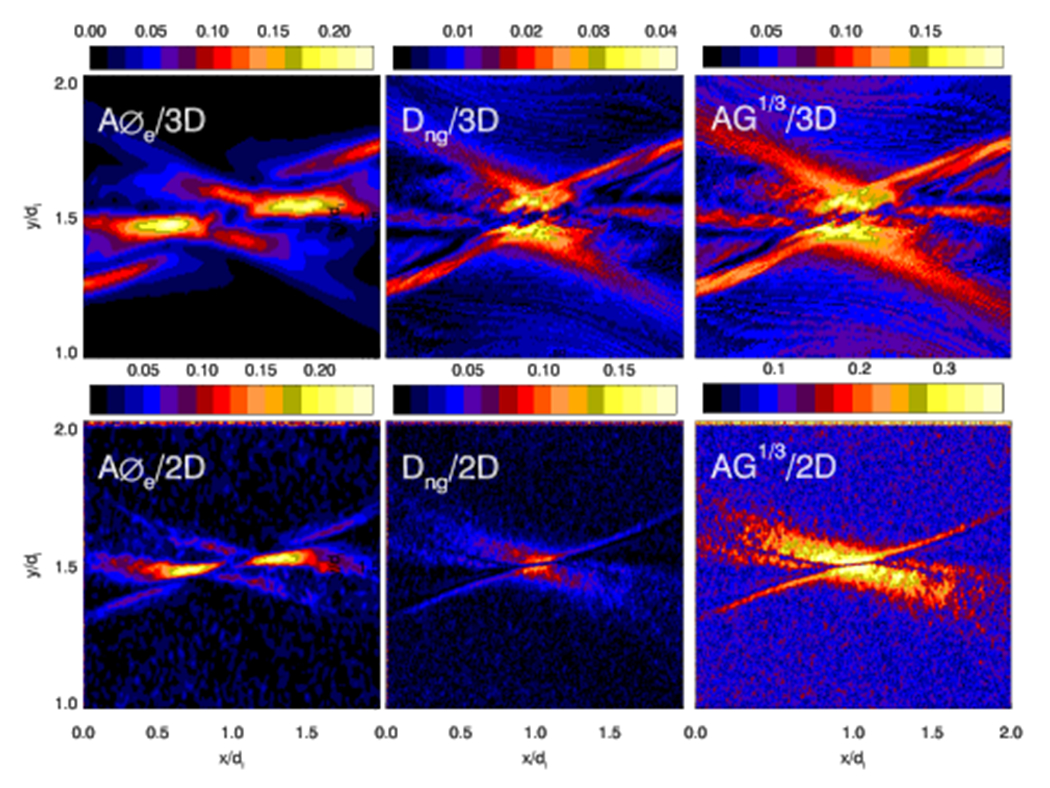
A∅e, Dng and AG1/3 in force-free reconnection simulations.
In 3D force-free simulation, turbulence broadens the EDR and the current sheet. The effect is traced by AG in Fig. 8, demonstrating agyrotropy can be used to trace turbulence in reconnection. Turbulence broadening and the enhancement of the current sheet are fundamentally important in magnetic reconnection because they could play important roles in fast magnetic reconnection16,32. Using agyrotropy measure to diagnose turbulence has several advantages: 1) the dimensionless measurements can be compared directly between observations and simulations; 2) The stochastic motion of particles is directly associated with turbulence and thus the agyrotropy measurement is a useful indicator of turbulence effects. If we combine the agyrotropy measurement with magnetic field and other physical quantities, we may better diagnose the role of turbulence in magnetic reconnection.
III. CONCLUDING REMARKS
Various physical processes in magnetic reconnection and plasma turbulence cause the electron orbits to significantly deviate from the usual guiding center behavior, leading to agyrotropy of their velocity distribution function. Quantification of agyrotropy effect on the pressure tensor has important applications in space and plasma physics. For example such measures are used to study the EDR in magnetic reconnections and in current sheets. However, the multitude of existing measures causes confusion and raises the question of how good these measures are, how many ways agyrotropy can be defined, and what is the best way to measure agyrotropy. In this paper we have attempted to answer these questions.
After considering the basic properties an agyrotropy measure should have, we show that the simplest way to measure agyrotropy is to use the rotational invariants of the pressure tensor. We have ruled out any measure based on the trace of pressure tensor I1. We found that all three previously defined agyrotropy measures are constructed based on I2 – the sum of the principle minors. We show that for field-aligned pressure tensor, all the I2-based measures except for A∅e are dependent on P‖, which is unphysical, and the dependence causes bias and ambiguity between extreme agyrotropy and gyrotropy. In addition, the normalization of Dng causes its scaling to depend on the local magnetic field and plasma properties, regardless of whether the pressure is field-aligned. A∅e is found to be the degenerate case of Q when P‖ = 0. However, instead of having a unique gyrotropic tensor for given parallel and perpendicular components, A∅e = 0 defines a family of tensors, most of which are not gyrotropic. This leads to the measurement of the departure from gyrotropy uncertain in 3D problems where pressure tensors are generally not field aligned. In addition, the definition in general does not account for all the effects of agyrotropy on the pressure tensor.
We introduce a new independent agyrotropy measure AG, which is defined based on I3. We show the properties of AG as well as those of other I2-based agyrotropic measures in Table I and AG clearly compares favorably. In this study we have examined the possible measures of the departure from gyrotropy based on all the rotation invariant operators of the pressure tensor. Our study has eliminated both I1 and I2-based measures, leaving us with the only I3-based measure AG.
TABLE I.
Comparison of Different agyrotropy Measures
| AG | Q | Dng | A∅e | |
|---|---|---|---|---|
| Rotation Invariant | I3 | I2 | I2 | I2 |
| Unique Gyrotropy Defined | Y | Y | Y | N |
| Field aligned measure independant of P‖ | Y | N | N | Y |
| Uniform Scaling | Y | Na | N | Y |
| Trace EDR in Harris reconnection | Y | Y | Y | Y |
| Trace EDR in Force-free reconnection | Y | Y | Y | N |
The scaling depends on P‖ when the tensor is field aligned.
Using PIC magnetic reconnection simulations, we demonstrate that AG traces the EDRs and separatrices in reconnections in both Harris and force-free current sheets. Both Q and Dng also show their highest values in the EDR. While AG, Q, and Dng agree qualitatively in these simulations, we must emphasize that the non-uniform scaling of Q and Dng makes quantitative analysis difficult. In space observations the magnetic field and plasma are highly nonuniform, to use agyrotropy quantitatively in analysis of data, a uniform scaling is essential. On the other hand, while A∅e can trace the EDR in Harris reconnection, it fails to trace the EDR and part of the separatrix in force-free reconnection simulations. This demonstrates the fundamental difference between the electron dynamics in Harris and force-free current sheets. These simulations highlight the importance of accounting for all effects of electron agyrotropy on the pressure tensor when defining a measure.
ACKNOWLEDGMENTS
We thank the anonymous referee whose criticisms and suggestions helped to improve the paper. We thank M. Swisdak for his very helpful discussion and critical comments on the manuscript. We also thank W. Daughton for his comments. We thank Kuznetsova for her helpful discussion on the construction of agyrotropy. We thank also the UCLA MMS team for the helpful discussion. We thank the participants of the Second MMS community Science Workshop (2017) who attended the first presentation of this work and kindly provided comments and feedback. HC is partially supported by MMS project, and by NASA grant No.NNX17AI19G. The simulations and analysis were carried out at the NASA Advanced Supercomputing facility at Ames Research Center under NASA High-End Computing Program.
REFERENCES
- 1.Huang K, Statistical Mechanics (John Wiley & Sons, Inc, 1966). [Google Scholar]
- 2.The contraction of yields a scalar quadratic function f(x) = ∑xiPijxj. Since is positive semidefinite, the quadratic function defines a family of ellipsoids (including their degenerate forms) with the pressure components as coefficients. Thus the pressure tensor can be conveniently represented by an ellipsoid (or its degenerate forms). In this paper when describing pressure tensor in geometric terms we refer to this representation.
- 3.Zenitani S and Nagai T, “Particle dynamics in the electron current layer in collisionless magnetic reconnection,” Physics of Plasmas 23, 102102 (2016), arXiv:1605.07472 [astroph.SR]. [Google Scholar]
- 4.Hesse M, Liu Y-H, Chen L-J, Bessho N, Kuznetsova M, Birn J, and Burch JL, “On the electron diffusion region in asymmetric reconnection with a guide magnetic field,” 43, 2359–2364 (2016). [Google Scholar]
- 5.Sonnerup BUÖ, “Adiabatic particle orbits in a magnetic null sheet,” J. Geophys. Res. 76, 8211 (1971). [Google Scholar]
- 6.Vasyliunas VM, “Theoretical Models of Magnetic Field Line Merging, 1,” Reviews of Geophysics and Space Physics 13, 303–+ (1975). [Google Scholar]
- 7.Harris EG, “On a plasma sheath separating regions of oppositely directed magnetic field,” Il Nuovo Cimento 23, 115–121 (1962). [Google Scholar]
- 8.Hesse M, Schindler K, Birn J, and Kuznetsova M, “The diffusion region in collisionless magnetic reconnection,” Phys. Plasma 6, 1781–1795 (1999). [Google Scholar]
- 9.Chen J, “Physics of the magnetotail current sheet,” Physics of Fluids B: Plasma Physics 5, 2663–2670 (1993), 10.1063/1.860704. [DOI] [Google Scholar]
- 10.Litvinenko YE, “Regular versus chaotic motion of charged particles in non-neutral current sheets,” Solar Physics 147, 337–342 (1993). [Google Scholar]
- 11.Speiser TW, “Particle Trajectories in Model Current Sheets, 1, Analytical Solutions,” J. Geophys. Res. 70, 4219–+ (1965). [Google Scholar]
- 12.Speiser TW, “Particle trajectories in model current sheets: 2. Applications to auroras using a geomagnetic tail model,” J. Geophys. Res. 72, 3919–3932 (1967). [Google Scholar]
- 13.Buechner J and Zelenyi LM, “Regular and chaotic charged particle motion in magnetotaillike field reversals. I - Basic theory of trapped motion,” J. Geophys. Res. 94, 11821–11842 (1989). [Google Scholar]
- 14.Chen J, “Nonlinear dynamics of charged particles in the magnetotail,” J. Geophys. Res. 97, 15 (1992). [Google Scholar]
- 15.Buechner J and Zelenyi LM, “Deterministic Chaos in The Dynamics of Charged Particles Near a Magnetic Field Reversal,” Physics Letters A 118, 395–399 (1986). [Google Scholar]
- 16.Che H, “How anomalous resistivity accelerates magnetic reconnection,” Physics of Plasmas 24, 082115 (2017), 10.1063/1.5000071. [DOI] [Google Scholar]
- 17.Hesse M, Winske D, and Kuznetsova MM, “Hybrid modeling of collisionless reconnection in two-dimensional current sheets: Simulations,” J. Geophys. Res. 100, 21815–21826 (1995). [Google Scholar]
- 18.Kuznetsova MM, Hesse M, and Winske D, “Kinetic quasi-viscous and bulk flow inertia effects in collisionless magnetotail reconnection,” J. Geophys. Res. 103, 199–214 (1998). [Google Scholar]
- 19.Pritchett PL, “Geospace Environment Modeling magnetic reconnection challenge: Simulations with a full particle electromagnetic code,” J. Geophys. Res. 106, 3783–3798 (2001). [Google Scholar]
- 20.Ricci P, Brackbill JU, Daughton W, and Lapenta G, “Collisionless magnetic reconnection in the presence of a guide field,” Phys. Plasma 11, 4102–4114 (2004). [Google Scholar]
- 21.Daughton W, Scudder J, and Karimabadi H, “Fully kinetic simulations of undriven magnetic reconnection with open boundary conditions,” Phys. Plasma 13, 072101–+ (2006). [Google Scholar]
- 22.Scudder J and Daughton W, ““Illuminating” electron diffusion regions of collisionless magnetic reconnection using electron agyrotropy,” J. Geophys. Res. 113, A06222 (2008). [Google Scholar]
- 23.Scudder JD, Holdaway RD, Daughton WS, Karimabadi H, Roytershteyn V, Russell CT, and Lopez JY, “First Resolved Observations of the Demagnetized Electron-Diffusion Region of an Astrophysical Magnetic-Reconnection Site,” Physical Review Letters 108, 225005 (2012). [DOI] [PubMed] [Google Scholar]
- 24.Burch JL, Moore TE, Torbert RB, and Giles BL, “Magnetospheric Multiscale Overview and Science Objectives,” Space Sci. Rev. 199, 5–21 (2016). [Google Scholar]
- 25.Aunai N, Hesse M, and Kuznetsova M, “Electron nongyrotropy in the context of collisionless magnetic reconnection,” Phys. Plasma 20, 092903 (2013). [Google Scholar]
- 26.Swisdak M, “Quantifying gyrotropy in magnetic reconnection,” Geophys. Res. Lett. 43, 43–49 (2016). [Google Scholar]
- 27.Khotyaintsev YV, Graham DB, Norgren C, Eriksson E, Li W, Johlander A, Vaivads A, André M, Pritchett PL, Retinò A, Phan TD, Ergun RE, Goodrich K, Lindqvist P-A, Marklund GT, Le Contel O, Plaschke F, Magnes W, Strangeway RJ, Russell CT, Vaith H, Argall MR, Kletzing CA, Nakamura R, Torbert RB, Paterson WR, Gershman DJ, Dorelli JC, Avanov LA, Lavraud B, Saito Y, Giles BL, Pollock CJ, Turner DL, Blake JD, Fennell JF, Jaynes A, Mauk BH, and Burch JL, “Electron jet of asymmetric reconnection,” Geophys. Res. Lett. 43, 5571–5580 (2016). [Google Scholar]
- 28.Ergun RE, Holmes JC, Goodrich KA, Wilder FD, Stawarz JE, Eriksson S, Newman DL, Schwartz SJ, Goldman MV, Sturner AP, Malaspina DM, Usanova ME, Torbert RB, Argall M, Lindqvist P-A, Khotyaintsev Y, Burch JL, Strangeway RJ, Russell CT, Pollock CJ, Giles BL, Dorelli JJC, Avanov L, Hesse M, Chen LJ, Lavraud B, Le Contel O, Retino A, Phan TD, Eastwood JP, Oieroset M, Drake J, Shay MA, Cassak PA, Nakamura R, Zhou M, Ashour-Abdalla M, and André M, “Magnetospheric multiscale observations of large-amplitude, parallel, electrostatic waves associated with magnetic reconnection at the magnetopause,” Geophys. Res. Lett. 43, 5626–5634 (2016), 2016GL068992. [Google Scholar]
- 29.Torbert RB, Burch JL, Giles BL, Gershman D, Pollock CJ, Dorelli J, Avanov L, Argall MR, Shuster J, Strangeway RJ, Russell CT, Ergun RE, Wilder FD, Goodrich K, Faith HA, Farrugia CJ, Lindqvist P-A, Phan T, Khotyaintsev Y, Moore TE, Marklund G, Daughton W, Magnes W, Kletzing CA, and Bounds S, “Estimates of terms in Ohm’s law during an encounter with an electron diffusion region,” Geophys. Res. Lett. 43, 5918–5925 (2016). [Google Scholar]
- 30.Zeiler A, Biskamp D, Drake JF, Rogers BN, Shay MA, and Scholer M, “Three-dimensional particle simulations of collisionless magnetic reconnection,” J. Geophys. Res. 107, 1230–+ (2002). [Google Scholar]
- 31.Che H, Drake JF, Swisdak M, and Yoon PH, “Electron holes and heating in the reconnection dissipation region,” Geophys. Res. Lett. 37, 11105–+ (2010). [Google Scholar]
- 32.Che H, Drake JF, and Swisdak M, “A current filamentation mechanism for breaking magnetic field lines during reconnection,” Nature 474, 184 (2011). [DOI] [PubMed] [Google Scholar]


