

Abstract
Three-dimensional (3D) printing and bioprinting have become a key component in precision medicine. They have been used towards the fabrication of medical devices with patient-specific shapes, production of engineered tissues for in vivo regeneration, and preparation of in vitro tissue models used for screening therapeutics. In particular, vat polymerization-based 3D (bio)printing as a unique strategy, enables more sophisticated architectures to be rapidly built. This progress report aims to emphasize the recent advances made in vat polymerization 3D printing and bioprinting, including new biomaterial ink formulations and novel vat polymerization system designs. While some of these approaches have not been utilized towards the combination with biomaterial inks, we anticipate their rapid translation into biomedical applications.
Keywords: vat polymerization, stereolithography, digital light processing, biomaterial inks, multi-material, bioprinting
Graphical Abstract

Recent advances in vat polymerization-based three-dimensional (3D) printing and bioprinting are discussed, including new biomaterial ink formulations and novel vat polymerization system designs. While some of these approaches have not been utilized towards the combination with biomaterial inks, their rapid translation into biomedical applications is anticipated.
1. Introduction
Vat polymerization (VP) is a three-dimensional (3D) printing method using photopolymerization to cure the liquid ink hosted in a vat into a volumetric construct in a layer-by-layer manner.[1–4] Stereolithography (SLA), as the primary technique of VP printing, enables relatively fast production of volumetric structures with precise internal and external architectures for widespread applications in home, art, and lately, biomedicine. The SLA printing methods use a laser beam that sweeps around polymerizing single lines of the ink until completing each layer in a raster scan mode.[5–9] In the process of SLA printing, a series of patterns of ultraviolet light is projected onto a vat containing the liquid ink to achieve photocrosslinking across the build volume.[10] The patterns being projected are typically the product of slicing of a 3D computer model, which are designed with a 3D drawing software, and sometimes obtained from medical scanning resources of patients such as computed tomography (CT) or magnetic resonance imaging (MRI) (Figure 1A–B). SLA printing uses a layer-by-layer method, in which the previous layer adheres on the building platform that moves to a defined position after polymerization to allow photocrosslinking of the next layer (Figure 1C).
Figure 1. VP-based 3D printing/bioprinting.

A) Patient-specific designs from medical scanning images. B) Biomaterial ink/bioink preparations. C) The VP printing process in a layer-by-layer manner. D) Exemplary applications of VP-printed constructs in biomedicine.
By having very small beam diameters, it is possible to produce very high resolutions (20 μm) with SLA printing,[3] which means that the quality of a printer depends solely on the physical limitations of the core components and materials, such as the light source, the build platform, the ink tank, and the ink itself.[11] More recently, the digital light processing (DLP) approach has emerged as an improved method in VP printing capable of achieving resolutions in the range of 25 to 50 μm.[3] In DLP printing, a projector based on the digital micromirror device (DMD) or liquid crystal display (LCD) serves as the source to project an entire two-dimensional (2D) pattern for each layer, making the printing much quicker comparing to SLA.[12]
The advantages of VP when used with clinical scanning data as the printing patterns further make it a powerful tool for applications in biomedicine, including the productions of patient-specific medical devices, functional human tissues for regeneration, and in vitro human-based tissue models for therapeutics screening (Figure 1D–F).[13, 14] Aided by patient-specific models printed with SLA, the operation times and risks are reduced in surgeries. To this end, SLA has been used to fabricate patient-customized implants, such as a device to fix the bone fracture, and artificial knees or hips.[15] SLA printing also enables to build the precisely engineered tissue scaffolds with biodegradable materials for regeneration.[16] However, limitations still exist for conventional VP in terms of printing resolutions and materials used to print. For example, the biomaterials used can be too soft to be printed or the printing of a single biomaterial might not be able to represent relevant tissues accurately.
Conventional VP methods and their biomedical applications have been extensively reviewed in previous publications.[3] In this progress report, recent evolutions of VP are highlighted in the design of the inks, as well as for their delivery or processing methods. We further focus on different strategies that promote higher printing speeds and enable multi-material printing capacities, as well as a modified vat polymerization-like method based on computer axial polymerization. We finally provide perspectives on how these various methods may transition towards biomedical printing to enable improved capacity in building medical devices and fabricate engineered living systems.
2. Recent progress in vat polymerization printing
2.1. Overview of biomaterial inks
The advances in biomaterials facilitate the application of VP printing in biomedicine. Resins have been developed to fabricate medical devices and implants, and photocrosslinkable hydrogels have been used for encapsulating cells, mimicking the extracellular microenvironments in the fabricated tissue constructs. Most photocurable resins feature the properties of high-stiffness and fragile macromers with high molecular weights (Mw), which enable the preparation of mechanically strong constructs.[17–19] For the fabrication of implantable devices, commercial resins are sufficient to meet their mechanical and biocompatible demands. Biodegradable polymers have been applied for clinical usage, including poly(ε-caprolactone) (PCL) and poly(α-hydroxy acids).[7] Acrylate-endcapped poly(ε-caprolactone-co-trimethylene carbonate) resins, which were prepared using acrylated trimethylene glycol (TMG) or poly(ethylene glycol) (PEG) as the linker, have been reported to produce microneedles, microcylinder, and microbanks through SLA printing.[20] As such, TMG-based photoconstructs can be degraded with surface erosion, and both surface erosion and bulk degradation achieved fast degradation of PEG-based constructs.[21] Femur constructs were printed with polyacrylate and hydroxyapatite and treated with supercritical carbon dioxide to remove unreacted monomer and toxic residues.[15] It was observed that the implanted femur integrated with the surrounding bone. Furthermore, new commercial resins, such as those from Formlabs[22] and EnvisionTec[23], are available in the market. These resins present biocompatibility classes ranging from I to IIa, which allow them to be used in dental guards, dental prosthetics, and surgical and implant parts for certain periods of time.
Despite the success in developing biocompatible resins and polymeric inks for VP printing, a general lack of suitable hydrogel-based biomaterials that meet the prerequisites for biological compatibility (thus cell encapsulation) and printability hinders the VP applicability towards bioprinting. In this section, we give examples of currently used bioinks in SLA and DLP bioprinting with varying degrees of success.
2.1.1. Synthetic materials
Acrylated PEG
PEG is a common biomaterial used in tissue engineering, which is biocompatible and hydrophilic. The incorporation of acrylate or methacrylate group is advantageous since it endows this molecule photocrosslinkability. Different Mw in acrylated PEG affect their mechanical properties. For example, networks formed with Mw of 8000 Da and below do not allow diffusion of myoglobin (Mw=22000 Da), but PEG-diacrylate (PEGDA) of Mw of 20000 Da or higher permit the transport of proteins such as ovoalbumin with Mw up to 45000 Da.[24, 25] Recently, PEGDA (Mw=6000 Da) was used to prepare complex volumetric structures with DLP printing (Figure 2A), which successfully modeled a non-cellular vascularized alveolar unit that was able to breath (Figure 2B).[26] However, non-degradability and solubility of PEGDA, as well as the poor adhesion for cells, hinder its application towards bioprinting in certain scenarios.[27] Fortunately, it can be modified to mimic the extracellular matrix (ECM) components and adhesion domains to improve cell behaviors. For example, hexapeptide, a cell-adhesive peptide that specifically interacts with integrin receptor on cell surface, was used as the modification of PEGDA to form ECM-like hydrogels and improve biocompatibility.[28, 29] NIH/3T3 fibroblasts showed improved long-term viability with increased Mw (700–10000 Da) of PEGDA after SLA printing. Adding RGDS peptides further enhanced proliferation, survival, and spreading of cells.[30] Mixing acrylic-PEG-collagen with PEGDA also enabled to promote attachment and spreading of cells. It was used to fabricate cantilevers with SLA printing as a sensor to test the contractile forces after seeding with cardiomyocytes.[31]
Figure 2. Examples of DLP-based bioprinted tissue-like constructs.

A) Entangled vascular networks printed with 20 wt.% PEGDA (Mw=6000 Da). B) DLP-printed alveolar model using PEGDA. Reproduced with permission.[26] C) The PVA-MA bioink with photoinitiator of Ru/SPS for DLP-based bioprinting. D) Examples of high resolution-printing with PVA-MA. E) Differentiation of encapsulated MSCs in PVA-MA or PVA-MA/GelMA. F) ECFCs seeded on the surface of PVA-MA or PVA-MA/GelMA hydrogels printed with DLP. Reproduced with permission.[37]
Poly (vinyl alcohol) (PVA)
PVA has been reported as a biomaterial for the engineering of the cartilage and bone.[32–34] PVA methacrylate (PVA-MA) also shows good biocompatibility and tailorable mechanical properties.[35, 36] PVA-MA, as well as its combination with gelatin methacryloyl (GelMA; see Section 2.1.2), have enabled DLP printing of tissue-like constructs at high resolutions (25–50 μm), based on a visible light photoinitiator, the tris(2,2’-bipyridyl)dichloro-ruthenium(II) hexahydrate (Ru)/sodium persulfate (SPS) (Figure 2C–D). Constructs printed with 10 wt.% PVA-MA/1 wt.% GelMA were beneficial for osteogenic and chondrogenic tissue formations (Figure 2E) and supported the spreading of endothelial cells on their surfaces (Figure 2F), indicating that PVA-MA/GelMA might be a promising bioink for VP-based bioprinting.[37]
2.1.2. Naturally derived materials
Naturally derived bioinks for the use in VP bioprinting can be extracted directly from animals, plants, and even human tissues or derived thereof. They are biocompatibility and exhibit low toxicity yet chronic inflammatory responses. Variability from batch-to-batch and low printability exist for some of these bioinks, constituting their main drawbacks.[26]
Chitosan
Chitosan is a deacetylated derivative of chitin, a natural polysaccharide regularly present in the exoskeleton of insects and crustaceans, and it is the second abundant biopolymer in nature.[38] Chitosan itself would not be photopolymerizable, yet via the introduction of substituent components (e.g., allyl), the resultant chitosan molecules can be photosensitive and upon light exposure, crosslink to form a 3D network.[39, 40] In addition, chitosan modified by the addition of azido-benzoic acid has been reported to gel in less than a minute under UV light.[41] Although modified chitosan has been used to print constructs through SLA,[39] it has not been used to encapsulate cells.
GelMA
One of the most used bioinks in bioprinting is GelMA, which forms a hydrogel when photocrosslinked with a photoinitiator.[42–45] GelMA is essentially a derivative of collagen, and therefore contains intrinsic bioactive moieties such as the adhesion sites for cells, making them an enabling bioink.[46–48] Wang et al. printed GelMA-based constructs using visible light-based DLP bioprinting.[49] Bioinks were combined with eosin Y as the photoinitiator and NIH/3T3 fibroblasts. The scaffolds were fabricated with a projector using a 522-nm wavelength. After culturing for 5 days, the majority of the cells adhered to bioprinted tissue constructs.
Allylated gelatin (GelAGE)
Similar to GelMA, GelAGE is also made of gelatin but instead of the addition of methacryloyl groups, it uses the thiol-ene chemistry to form carbon-carbon double bonds.[19] By reacting allyl glycidyl ether (AGE) with gelatin, GelAGE can be obtained. Bertlein et al. have recently researched the use of GelAGE as a bioink for DLP-based 3D biofabrication with visible light (390–500 nm) using Ru/SPS as the photoinitiator as well as UV light (320–390 nm) using Irgacure 2959 as the photoinitiator.[50] In both cases, cytocompatibility was observed with encapsulated chondrocytes.
Methacrylated hyaluronic acid
Hyaluronic acid (HA) is a natural polymer present in the ECM frequently found in connective and cartilage tissues. HA has been widely adopted for 3D bioprinting, such as being used in combination with different bioinks to improve their biological properties and gelation behaviors.[51] Lam et al. reported using HA methacrylate (HAMA) in a bottom-up SLA bioprinting method to encapsulate swine-derived chondrocytes, where they demonstrated that the cells remained viable and formed cartilage-like tissues after 14 days.[52] A mixture of glycidal methacrylate-HA (GM-HA) and GelMA was also used for fabricating prevascularized tissue constructs using DLP bioprinting.[53]
Silk Fibroin (SF)
SF, found in the silkworm Bombyx mori, is a fibrous protein naturally, which consists of a repeating pattern of amino acids.[54] It has been used before in additive manufacturing and tissue engineering.[55] Adding methacrylate groups to the side groups of SF containing amines allows it to be photocrosslinked, and the degradation time can be tuned depending on the degree of methacrylation. Kim et al. have used methacrylated silk (Sil-MA) as the bioink to construct porous scaffolds using a DLP bioprinter, where they achieved a higher compressive strength than those displayed by GelMA.[55] Rapid fabrication times ensured the cells to remain undamaged and grow well-distributed.
2.2. Bottom-up versus top-down VP printing methods
Most current VP printing techniques either use a top-down or bottom-up approach when printing a structure (Figure 3A). Bottom-up systems have the build plate submerged in the vat containing the biomaterial ink and the light source under the vat. As a result, the light can be projected through the optically clear vat bottom, through which the ink is photopolymerized. Each layer then attaches to the layer on top of it, or to the build plate (for the first layer); the plate moves a certain height upwards to continue the printing of the next layer. On the other hand, a top-down system would start by having the build plate submerged in the vat just as deep as the first layer. The light would then be projected from the top of the system and onto the biomaterial ink crosslinking a layer that would attach on top of the moving build plate. The build plate would then move downwards and deeper into the vat for each additional layer and until the full construct is printed.[56]
Figure 3. Comparison of bottom-up and top-down methods in DLP-based printing.

A) Schematics of the i) bottom-up and ii) top-down systems. Reproduced with permission.[56] B) Comparison of the two constructs of the same pattern printed by i, iii) bottom-up and ii, iv) top-down systems. C) Crossed layers of parallels structures printed by i, iii) bottom-up and ii, iv) top-down systems. D) 3D disks printed by i) bottom-up and ii) top-down systems. Reproduced with permission.[57] E) Pulling-up force increases with the increased velocity in the bottom-up method. Reproduced with permission.[58] F) Changes of light power across the different wavelengths of the bottom-up and top-down methods. Reproduced with permission.[57]
Several qualitative comparisons can be observed in Figure 3B–D, where the two methods present different results when printing certain structures.[57] For constructs with a uniform aspect ratio (Figure 3B), it can be noticed that both approaches presented an adequate performance generating smooth and defined surfaces. When the objects were longer than wider (Figure 3C), cracks might appear using the bottom-up approach as the transversal area would not be enough to sustain the pulling forces that acted on the construct. Finally, for components having a larger solid surface area per layer (Figure 3D), the top-down approach did not perform very well since the thickness of the printed layers did not tend to be homogeneous and consistent. It is important to emphasize that these results were obtained with a single type of material (Al2O3-based ceramic slurry), and thus the examples illustrated provide a good understanding of how these two methods would contrast when extending to a variety of other inks.
As such, the two methods possess some key differences that suit them better for certain types of printing. The most relevant feature of the top-down approach is that it permits softer materials to be printed since some forces being exerted on the structure, while pulling it up in the bottom-up method, do not exist (Figure 3E).[57, 58] This is very attractive for bioprinting applications as the bioinks are typically based on hydrogels, which are generally weak in their mechanical properties. Also, with this approach, images are projected directly into the biomaterial ink without an extra interface surface as in a bottom-up system. This prevents the light power from being reduced or the pattern from being distorted due to unclean or scratched optically clear window in the latter setup, as seen in Figure 3F. It is also essential to consider if the ink allows oxygen inhibition, as having the ink exposed directly to the air might produce certain levels of oxygen inhibition that would normally not happen in a bottom-up system as shown by Santoliquido et al.[57] This however, could be an advantage or disadvantage depending on the specific cases. Likewise, the top-down approach might produce irregular layers as the ink might not settle equality in the surface.[57, 58] Yet it is necessary to consider many variables such as the vat’s bottom material, the time of exposure, and the biomaterial ink being printed. Extended discussions on this topic are presented by Zhou et al. and Santoliquido et al.[57, 59]
In addition, the bottom-up system features a much lower amount of biomaterial ink to be used than the top-down system, since it is only necessary to ensure a layer of ink as thin as the layer thickness for the build plate to be submerged in. The bottom-up system also possesses the ability to, in principle, print any height of constructs without worrying about the vat height in comparison with the top-down approach, where vat height should be higher than the constructing height.[57] Furthermore, the bottom-up approach allows for a smaller probability of contamination in multi-material printing, as will be explained later in Section 2.4.
2.3. Continuous fast VP printing
One of the main disadvantages of contemporary additive manufacturing is the slow object fabrication rates due to the time-consuming, stepwise approaches of this class of technology. The continuous VP printing is a technique that is designed to overcome the speed problem in VP printing by increasing the fabrication velocities and generating objects with smooth surfaces. Several approaches have been developed to archive fast printing, Continuous Liquid Interface Production (CLIP) and High-Area Rapid Printing (HARP) for instance, which will potentially promote biomedical applications of VP in the future.
2.3.1. CLIP
CLIP is one of the first approaches of continuous VP printing.[60] This process utilizes an oxygen-permeable interface beneath the DLP printer’s UV image projection plane to generate a constant liquid volume (dead zone) between the window and advancing part caused by the inhibition of polymerization (Figure 4A). The control in the inhibition of free-radical polymerization due to oxygen, as it restricts the photopolymerization of photocurable inks in general, is a key feature to archiving a considerable reduction in the DLP printing time.
Figure 4. CLIP-based continuous fast printing.

A) Schematic of the CLIP system. The oxygen-permeable window creates a persistent liquid interface in the middle of the elevating platform and the photocrosslinked part leading to polymerization inhibition. CLIP enables fast and layer-less printing achieve by the build plate continuously moving and the projected images simultaneously changing. B) The dead zone thickness is reduced with the photon flux increasing. Pure oxygen promoted the dead zone thickness, and the dead zone vanished when nitrogen was used under the window. C) Constructs printed by the CLIP, including the micropaddles (50 μm in stem diameter), the Eiffel Tower (10 cm in height), and the shoe cleat (>20 cm in length). Reproduced with permission.[60] D) Workflow of the digital print denture. Reproduced with permission.[61]
The “dead zone” is generated by using an oxygen-permeable fluoropolymer window, which also provides chemical inertness and UV transparency. The depth of this region can be controlled by several parameters such as the photon flux, ink curing dosage, and photoinitiator absorption coefficient (Figure 4B):
If there is an increase in photon flux or photoinitiator absorption coefficient, the concentration of free radicals in the ink will also rise leading to a decrease of the initial oxygen concentration. Polymerization will begin at the threshold level where there is no oxygen, yet free radicals still exist.
Adjusting the dead zone thus provides a layer of renewal ink between the window and the moving part. However, the dead zone can typically be only tens of micrometers in thickness, which is typically sufficient to eliminate the possibility of adhesion to the window but too small to achieve a smooth ink flow beneath the polymerized part, mainly for objects with larger cross-sectional areas. This issue limits the process to only very low-viscosity printable materials, or designs with small cross-sectional areas.
The photopolymerization occurs over the dead zone with a determined cured thickness that depends on the photon flux, photoinitiator absorption coefficient, and exposure time (positive correlation), as well as the ink curing dosage and ink absorption coefficient (negative correlation). It is essential to mention that part of the resolution of the printing when using CLIP is inversely determined by the optical absorption height, which is a property of the ink. The projected pixel size determines lateral resolution as ha affects axial resolution.
The printing speed in CLIP is derived from the dead zone thickness, the cured thickness, and the optical absorption height, therefore is only limited by the ink curing rate and viscosity, not by stepwise layer formation. At least 300 mm h−1 of printing speeds can be achieved with a combination of a 20-μm dead zone thickness and a 100-μm optical absorption height. Moreover, speeds higher than 1000 mm h−1 can be obtained by lowering the printing resolution and setting a 300-μm optical absorption height.
Studies show that this technique is only compatible with oxygen-sensitive ink chemistries and it can produce parts from ceramics, biological materials, and soft elastic materials. In addition, it is important to consider the fact that the dead zone thickness will become thinner as the pulling speed increases, leading to possible window adhesion creating an unstable process as in the conventional DLP processes. The minimum empirical dead zone thickness ranges from 20 to 30 μm. Therefore, CLIP offers a reliable but still limited method for fast printing (hundreds of mm h−1) with a tradeoff between the print speed and the dead zone thickness, but it can provide quality prints if the correct parameters regarding the ink, object size, and dead zone properties are archived (Figure 4C).
Continuous printing techniques aim to enable VP printing to the manufacturing sector. Carbon, the world’s leading digital manufacturing company, released the first digitally produced denture (Lucitone Digital Print™ Denture) (Figure 4D), which was approved on August 26, 2019 by the United States Food and Drug Administration (FDA).[61] The fabrication process relies on a CLIP-based DLP printing system. Using the Lucitone Digital Print™ 3D Denture Resin and following the workflow (scan, print, wash, and fuse), the printing of the dentures is fast and straightforward to meet the increasing patient demand potentially in a patient-specific manner.
2.3.2. HARP
Different approaches of continuous printing have been explored since the polymerization reaction used in VP is particularly exothermic at high printing speeds. Very recently, Mirkin and colleagues have reported a rapid DLP printing method, i.e., HARP, that substitutes the dead layer used in the previous CLIP approach with a flow of immiscible fluorinated oil beneath the UV-curable resin.[62] HARP is able to distribute, at uniform velocities, a laminar flow of fluorinated oil below the printing layer by employing a pair of inlet and outlet manifolds that allow the interfacial adhesion at the built region, where the optical distortions are minimized (Figure 5A). Since it is necessary to dissipate the heat generated in the polymerization reaction, the oil is recirculated through a heat exchanger that further enables to temperature control thermostatically over the printing vat. Additionally, light scattering is reduced by the continuous filtration of microparticles created in the printing process. Chemours Krytox GPL or Solvay Fomblin were preferred options for the oil phase as they present higher densities and omniphobic properties than most inks.
Figure 5. Mobile liquid interface-based HARP.

A) Schematic showing the printer setup. B) Infrared thermal images of the printed constructs under different conditions: i) stationary print interface ii) mobile interface; and iii) mobile interface and cooling. C) Examples of HARP-printed structures: i) a hard, machinable polyurethane acrylate part; ii) a silicon carbide ceramic lattice after post-treatment; iii and iv) a printed butadiene rubber structure iii) in the relaxed state and iv) in tension; v) a polybutadiene rubber; and vi) a hard polyurethane acrylate lattice (height is around 1.2m) printed in less than 3 h. Reproduced with permission.[62]
Since one of the objectives of the HARP technology is heat dissipation, a print test was performed with three different flow conditions in which the mobile interface and the oil cooling were evaluated (Figure 5B). The thermal images showed that the mobile interface effectively dissipated the heat into the oil layer, and oil cooling promoted temperature stability.
The elimination of the oxygen-permeable window used in CLIP enables HARP the possibility of fabricating objects with oxygen-sensitive chemistries, as well as oxygen-insensitive resins. This feature was demonstrated by printing various resins (Figure 5C). An example is the printability of the hard polyurethane resin (Figure 5Ci), which could be used optimally in HARP under a vertical print speed of 120 μm s−1 with a resolution of 100 μm. The ceramic resin could also be crosslinked by thiol-ene click chemistry at a vertical print speed of 120 μm s−1 and resolution of 100 μm; subsequently, this printed construct could further produce a silicon carbide structure through a post-treatment at high temperature to remove the organic components in a pyrolysis process (Figure 5C ii). In comparison, the butadiene rubber resin required a much slower speed (30 μm s−1) to print since it presents a higher viscosity and lower reactivity (Figure 5C iii-v). Importantly, the constructs fabricated with this approach showed isotropic mechanical properties similar to molded parts achieving a high resolution (250 μm) at substantial scales (up to 1.2 m × 30 cm × 30 cm) (Figure 5C vi).
However, there are still several challenges limiting the generation of structures with industrially relevant properties, such as lack of high-speed optical systems. In addition, full use of large-scale printing capabilities will need the improvement of VP inks with lower volumetric contractility since the print stability is affected by the volumetric reduction faced during the ink solidification at this scale.
2.4. Multi-material VP printing
Single-ink printing is a major limitation of most additive manufacturing techniques as it will not always portray correctly the different characteristics of a structure. For this reason, several studies have found multi-material 3D printing to be very practical, and in fact, oftentimes demanded, since it allows a single printed construct to achieve heterogenous features. This means that by allowing different materials to coexist, it is possible to fabricate constructs with different mechanical, electrical, chemical, and/or optical properties, among others. This same idea readily extends to bioprinting as it enables the possibility to have different bioinks, each with the potential to have distinct matrix properties, bioactive molecule concentrations, cell types, as well as fine structures.
Nevertheless, the methods used to generate the swap of biomaterial inks are more complicated in photopolymerization-based VP printing than those of, for example, extrusion-based printers. With the latter, it is possible to install multiple printheads, each connected to a different biomaterial ink, to allow convenient switching. For example, we have previously designed a multi-channel, single-nozzle printhead that permitted rapid switching between bioinks to achieve continuous multi-material extrusion bioprinting.[63, 64] This was further expanded recently to a multi-channel, multi-nozzle system to facilitate volumetric multi-material extrusion printing at high-throughput, as demonstrated by Lewis and colleagues.[65] On the other hand, some interesting techniques have been lately reported to overcome the difficulties of material swapping to achieve multi-material VP-based 3D printing and bioprinting, each with a unique approach and tackling different paradigms.
2.4.1. Ink exchange in VP printing
Either changing the vat hosting different inks, or a cleaning-and-filling vat sequence is needed for diverse materials to be printed during the same printing session. Even so, the way these two techniques are implemented allows them to generate different outputs. By conducting the complete vat exchange, only a discrete combination can be accomplished, yet no gradients could possibly be achieved. This means that a layer can only be made up a 100% of the ink in a vat being submerged in, instead of being able to create a mix of multiple inks. This is due to the pure nature of the technique in which the build plate (and associated already printed structure) is taken off the vat, cleaned, and then dipped back into either a new or the same vat containing a different ink.
Maruo et al. first presented a way to manually change vats containing photocurable polymers with different electrical and optical properties by draining the old ink, rinsing the structure, and then filling the vat with new ink in position for the printing to continue.[66] Although this is a working method, some other problems have surged, such as the extensive time spent, the effort put into the manual operations, and the low level of replicability. As a result, many others then attempted to tackle these challenges by creating highly automatized and standardized systems. By using motors and sensors, the different vats can be moved and exchanged at defined positions for the build plate to be accurately submerged in them. Zhou et al. reported the development of a bottom-up system that automatically changed between vats that contained different inks, allowing the swap of inks while minimizing the cross-contamination between them. By using a bottom-up system, it was possible to reduce the amount of ink being used, as well as lowering the contamination between inks since only a small part of the structure was submerged.[59] Apart from that, a two-phase cleaning process was applied every time the ink was to be exchanged (Figure 6A). The cleaning sequence involved two different stages: the rough cleaning stage used a soft brush to remove the exceeding ink that was left at the bottom of the structure; in the second cleaning step, the construct was submerged in 90% isopropanol and brought under ultrasound to remove all ink that could be left. This clean construct was then submerged into the next ink to continue the additive manufacturing process. In this study, the inks used were Perfatory™ SI500 and Perfactory™ Acryl R5 from EnvisionTec.
Figure 6. Exchanging inks in the vat for the multi-material VP printing.
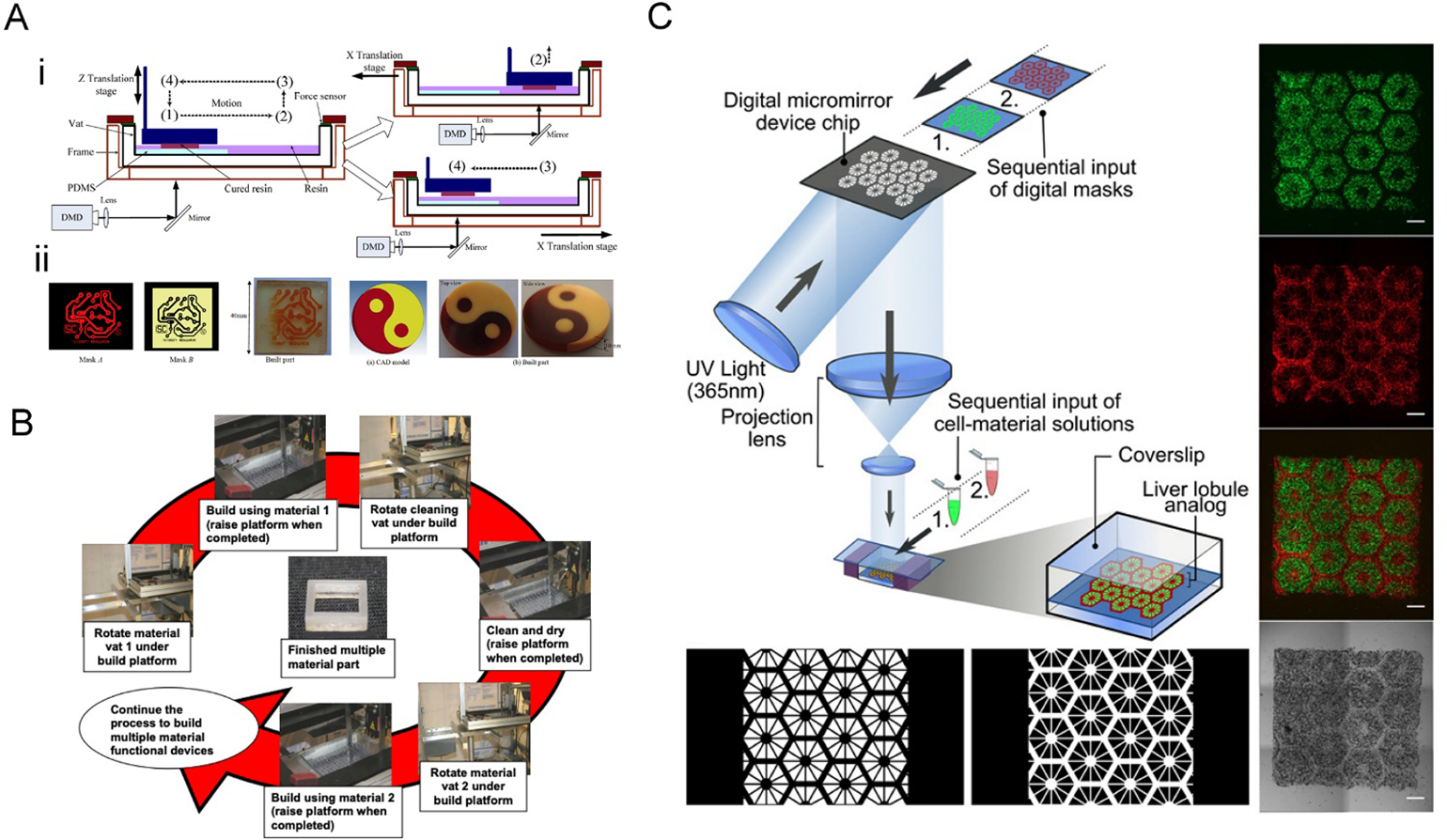
A) The two-channel multi-material DLP printing platform. i) The vat was divided into two channels, and only the printing channel with the PDMS film would be exposed to the images. After the photocrosslinking at position (1), the vat was moved to position (2), followed by elevating up and backing to the position (4) for the next layer of curing. ii) Examples of printed multi-material constructs. Reproduced with permission.[59] B) Operational principle of a multiple material stereolithography (MMSL) system. The print platform is submerged into the vat with the first ink to finish the first pattern fabrication; after raising the platform, a cleaning vat is rotated to clean the platform; then the print platform is lifted out from cleaning vat after cleaning and drying, and the vat with the second ink is rotated under the build platform. Reproduced with permission.[70] C) DLP-bioprinting of a vascularized hepatic model by sequentially inputting two different bioinks. The lobule structure was bioprinted with hiPSC-derived hepatic progenitor cells[26] and the sinusoids with HUVECs and ADSCs (red). Reproduced with permission.[71]
Top-down systems have also been reported to be implemented on a vat-changing printing system, but due to its nature, ink waste and contamination probability can be significantly higher compared to bottom-up if not appropriately managed. Ge et al. developed a micro-DLP printing system that enabled high-resolution multi-material four-dimensional (4D) printing by using a digital micro-display device, which allowed resolutions of up to ~1 μm using photocurable methacrylated soft active materials (SAMs) as inks.[67] These materials can exhibit large elastic deformation in response to certain stimuli, thus creating functional active components. To accomplish this, a combination of materials with different properties was required. This would make it possible to manipulate the form of the parts fabricated using one ink, while maintaining the structure built with another leaving the shape unchanged, to achieve the overall deformation of a printed object. The material exchange was achieved by an automated mechanism in the printing system, similar to the one presented for the previous example. The system would autonomously change the vats containing different inks in each and would clean the parts being printed to avoid cross-contamination.
In both approaches, it is important to be aware of the components used for these systems as the fidelity and resolution of the motion actuators could profoundly affect the printing. It is also crucial to consider the force being applied by the cleaning process on the printed objects, in particular for a method like these to be applied for bioprinting that involves soft biomaterials. In these cases, a top-down system might be more adequate and slight contamination might be acceptable to ensure that the structures do not break.
On the other hand, to avoid changing vats in between layers, it is also possible to perform the washing of the biomaterial inks in-place. This would result in a faster method but could present other difficulties such as increased cross-contamination and a waste of inks. Differently, it could also create new opportunities, including generating a seudo-complete gradient by continuously adding the ink and changing the amount being pumped at every moment. Both Han et al. and Arcaute et al. designed similar systems that could automatically switch the inks by pouring the solutions with a pipette into a customized small vat, and later washing the current ink before switching to the next one in a DLP and a SLA printing system, respectively.[68, 69] Inamdar et al. developed an automatic pumping systems for the filling/leveling of the vat could ensure a closely constant level of the ink as they provided a ±5 μm precision in control. Moreover, these systems operated at resolutions of nearly 0.004” using a solid-state laser (Lightwave® Electronics) to achieve high resolution (Figure 6B).[70] Based on this technique, the fabrication of 3D scaffolds for tissue engineering was further demonstrated.[71] Chen and colleagues produced a functional hepatic tissue model consisting of human-induced pluripotent stem cells (iPSCs)-derived hepatic progenitor cells, as well as a mixture of human umbilical vein endothelial cells (HUVECs) and adipose-derived stem cells (ADSCs), by changing the bioinks (Figure 6C). The model could be effectively used for disease modeling and drug screening.
2.4.2. Microfluidics-based vats in VP printing
Like automation in vat exchanges, that in fluidic exchanges comparing to manual operations will further improve the capacity of multi-material VP printing. We recently designed a microfluidic device to turn a standard DLP bioprinter into a multi-material DLP bioprinting platform.[72] To achieve rapid exchange of the different bioinks within a small volume, a microfluidic chip was designed and applied as the vat of the bioprinting system (Figure 7A). The design of the microfluidic device consisted of a polydimethylsiloxane (PDMS) chamber containing four bioink inlets and the infused bioinks and two poly(methyl methacrylate) (PMMA) sheets that held everything together. Interestingly, in the vat made of the closed microfluidic chip, a fixed tower allowed to alter the spacing between the build plate (glass on top) and the thin PDMS membrane sitting on top of this tower (Figure 7B). The closed-chip nature then allowed for pressure-driven rapid washing of the bioinks when changing the materials, achieved through automated digital controls of the bioink flows. A washing sequence was also introduced to avoid cross-bioink contamination. The three branches in the central region were used to broaden the directionality of the flow, but also to reduce flow forces imposed on the bioprinted constructs. The layers of the printed construct could be adjusted in 100-μm steps, and the practical lateral resolution was found to be close to 10 μm (with a 5 × 5-mm2 illumination area).
Figure 7. Multi-material bioprinting with a microfluidic reservoir.
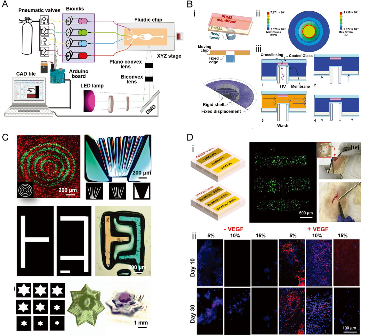
A) Illustration of the bioprinter, including the microfluidic chip and the optical platform. B) 3D bioprinting using the microfluidic chip-based bioink reservoir. i) The microfluidic device is containing the PDMS membrane at the center of the chamber. ii) The simulation of stress and strain of the PDMS membrane upon piston elevation. iii) The four-step multi-material bioprinting process. C) Bioprinted multi-material constructs based on PEGDA. D) Bioprinted multi-material constructs based on PEGDA and GelMA. i) Schematic of the bioprinted constructs with 35 wt.% PEGDA as the frames and strips composed of 5 wt.%, 10 wt.%, and 15 wt.% GelMA, as well as those containing VEGF; the constructs were implanted in a rat subcutaneous model to assess vascularization. ii) Immunostaining of CD31 (red), counterstained for nuclei (blue). Reproduced with permission.[72]
This multi-material bioprinting method was demonstrated to be suitable for the fabrication of soft bioinks such as those based on PEGDA and GelMA (Figure 7C), since no harsh washing processes as those discussed in Section 2.4.1 were further involved. Bioprinted constructs containing vascular endothelial growth factor (VEGF) showed improved neovascularization capability following in vivo implantation, as compared to their counterparts without VEGF (Figure 7D). Moreover, the higher concentration of GelMA within an implant expressed less CD31, which might be the result of the slower invasion of cells in the denser hydrogels.
2.5. Multi-wavelength VP printing
2.5.1. Multi-material patterning
Traditional multi-material VP printing strategies through ink exchanging are capable of achieving heterogeneity in the axial direction, yet the control of the multi-material compositions on the other two dimensions remains to be a challenge due to the layer-by-layer vertical fabrication nature. As a result, multi-material actinic spatial control (MASC) was developed and has emerged as an advanced technique to achieve true heterogeneity in all three axes. As its name states, the MASC system takes advantage of the actinic property of ink, which means that the ink is able to exhibit different chemical changes produced by radiating distinct amounts of energy generated by visible light and UV regions of the light spectrum.
Boydston and colleagues presented a way to use MASC and a multi-component ink to fabricate different spatially heterogenous structures with two distinct materials that were combined in the same ink and vat (Figure 8A).[73] This was attained by combining acrylate- and epoxide-based components, which could be selectively cured by visible and UV light irradiations, through the use of Irgacure 819 (λmax = 295, 370 nm; λcutoff = 450 nm) and a mixture of triarylsulfonium salts (TAS, λmax = 220, 303 nm; λcutoff = 390 nm) as photoinitiators, respectively (Figure 8B). This could potentially allow the correlation of multi-color images with multi-material compositions.
Figure 8. Two-wavelength MASC patterning.

A) The printer setup. Visible light and UV light are computer-controlled in MASC printing. B) Representation of the HEA-1 MASC ink formulation. The multicomponent photoresin enabled different materials in different stiffness to be printed by visible and UV light. C) Representative constructs printed with the BA-1 MACS ink formulation. D) The swelling of a sea star printed with HEA-1 MASC. The purple part was cured by the UV light, and the white part corresponded to the visible light. Reproduced with permission.[73]
Specifically, under longer wavelengths (visible range), it was mainly the acrylate component that was cured; under shorter wavelengths (UV range), a combination of epoxide and acrylate was obtained. This allows the production of multi-material parts containing stiff epoxide sites compared against soft organogels and hydrogels. As a result, variations in MASC formulations may drastically change the mechanical properties of the printed constructs. The samples printed using diverse MASC formulations thus possess mechanical anisotropy, spatially controlled chemical heterogeneity, and spatially defined swelling that facilitates 4D printing.
Examples printed with the ink made by butyl acrylate (BA), epoxy-functionalized polyhedral oligomeric silsesquioxane (EPOX-ePOSS), and hexanediol diacrylate (HDDA) showed different optical properties (Figure 8C). Transparent regions corresponded to segments printed with visible light; in contrast, the opaque segments were produced with UV light. In particular, the printed “hand” had interior “bones” as hard segments were fully surrounded by the softer continuous “flesh” phase. Constructs printed with consecutive UV and visible light resulted in different swelling ratios, which were used to build 4D motions. It was documented that the mass and volume in deionized water for 2-hydroxyethyl acrylate (HEA-1) samples printed with visible light were almost 2.2 times or higher compared to the ones printed with UV light. Thermal post-curing was used to also reduced the swelling of samples printed with UV light. Visible-light printed BA samples swelled 1.7 times more by mass, and 2.0 times more by volume, than samples printed with UV light. A sea star printed with HEA-1was designed with small hard segments along the central top axis of each arm (printed with UV light) to function as a strain-limiting region to guide actuation (Figure 8D).
2.5.2. Inhibition pattering
A different multi-wavelength VP printing approach is the volumetric polymerization inhibition patterning (VPIP), which relies on the inhibition of polymerization without using an oxygen-permeable window leading to the creation of new printing features in a truly 3D manner and overcoming the limitations of the CLIP technique.[74] The generation of an uncured liquid region is again an important element to avoid bottom adhesion and achieve a continuous performance. Therefore, in this strategy, two light sources of different wavelengths are projected from below through the same glass window, where one source initiates polymerization of the ink by an illuminated pattern, but the other inhibits the polymerization reaction (Figure 9A).
Figure 9. Two-wavelength photoinitiation and photoinhibition patterning.

A) Setup of the printer with the UV (365nm) inhibition light and the visible initiation light. B) Structures CQ (photoinitiator), EDAB (co-initiator), and o-Cl-HABI (photoinhibitor). C) The absorbance spectrum of CQ and o-Cl-HABI. D) The inhibition height with different intensity ratios (the incident irradiation wavelengths (IUV,0/Iblue,0)) and resin absorbance (huv). E) Simultaneous photoinitiation and photoinhibition for printing front-side variable structures, using intensity-modulated inhibition light and constant initiation light. Reproduced with permission.[74]
The photopolymerizable resin formulations must be carefully selected, specifically the photoinitiators and the photoinhibitors. For example, camphorquinone (CQ) was used as the photoinitiator, and ethyl 4-(dimethylamino) benzoate (EDAB) was used as the co-initiator respectively, but bis[2-(o-chlorophenyl)-4,5-diphenylimidazole] (o-Cl-HABI) served as the photoinhibitor (Figure 9B). The absorbances of these three components played an important role in enabling polymerization to be initiated at one wavelength and inhibited at another. As shown in Figure 9C, CQ presented a poor absorbance near the UV region of the spectrum but a reasonable absorbance under blue light; on the other hand, o-Cl-HABI showed a very low absorbance near the blue region and a moderate absorbance under the near-UV light of the spectrum.
When both blue and UV lights are projected at the same time onto the uncured ink, an “inhibition volume” is created, allowing continuous printing. The thickness of this region can be regulated by changing the ratio of intensities of the two light sources or by altering the photoinitiator/photoinhibitor amounts of the ink (Figure 9D). Different from CLIP, this VPIP method is possible to be scaled for a rapid production of objects with large cross-sectional areas because the inhibition volume thickness can enhance the ink reflow, as well as supporting an expanded monomer palette and viscous ink formulations. Still, increases in the thickness of the inhibition volume, through changing the light parameters, ink properties, or photoabsorber concentrations, typically lead to a decrease in the polymerization rate triggering slower printing speeds, with the fastest printing speed attainable at approximately 2 m h−1.
Importantly, the VPIP approach allows front-side variable patterning of a printed structure through the intensity-modulated inhibition light, while ensuring far-surface curing of the ink via the constant initiation light (Figure 9E). This is a critical feature enabling axial heterogeneity in the architecture of the printed constructs otherwise not conveniently achievable using a single-light projection-based VP printing.
Overall, the application of multi-wavelength systems in VP printing is a new direction that aims at the applications towards generating volumetric heterogeneity or improving resolutions, potentially enabling the rapid printing of personalized constructs.
2.6. Volumetric tomographic printing
The current paradigm of VP printing relies on layer-by-layer construction, based on sliced standard models. Building an object in this fashion restricts the type and complexity of structures that can be created. Moreover, the printing time of this approach is typically determined by the size of the model, especially the axial direction. This consideration is particularly important in bioprinting as extended printing times would inevitably cause unwanted damage to cells. Thus, an improvement in the conventional VP printing method is needed.
Recently, a volumetric tomographic printing method termed as computed axial lithography (CAL), which is deem as a volumetric VP-like printing approach features layer-less fabrication, was developed inspired by CT imaging applied in reverse.[75] This method enables a layer-less and continuous creation of the entire object by rotating the ink container and irradiating a set of intensity-modulated 2D patterns onto it (Figure 10A i and ii). The rotation and patterning are controlled by a program computed with a Radon transform, using the reversed principle of CT imaging.[75] Therefore, this method enables the continuous creation of full-size objects through rotation rather than sequential layer-by-layer construction; also, since a construct is freely suspended within the vat, there is no need for additional support to create complex self-supporting architectures. Furthermore, it is capable of printing 3D constructs surrounding any existing components.
Figure 10. Volumetric tomographic (bio)printing.
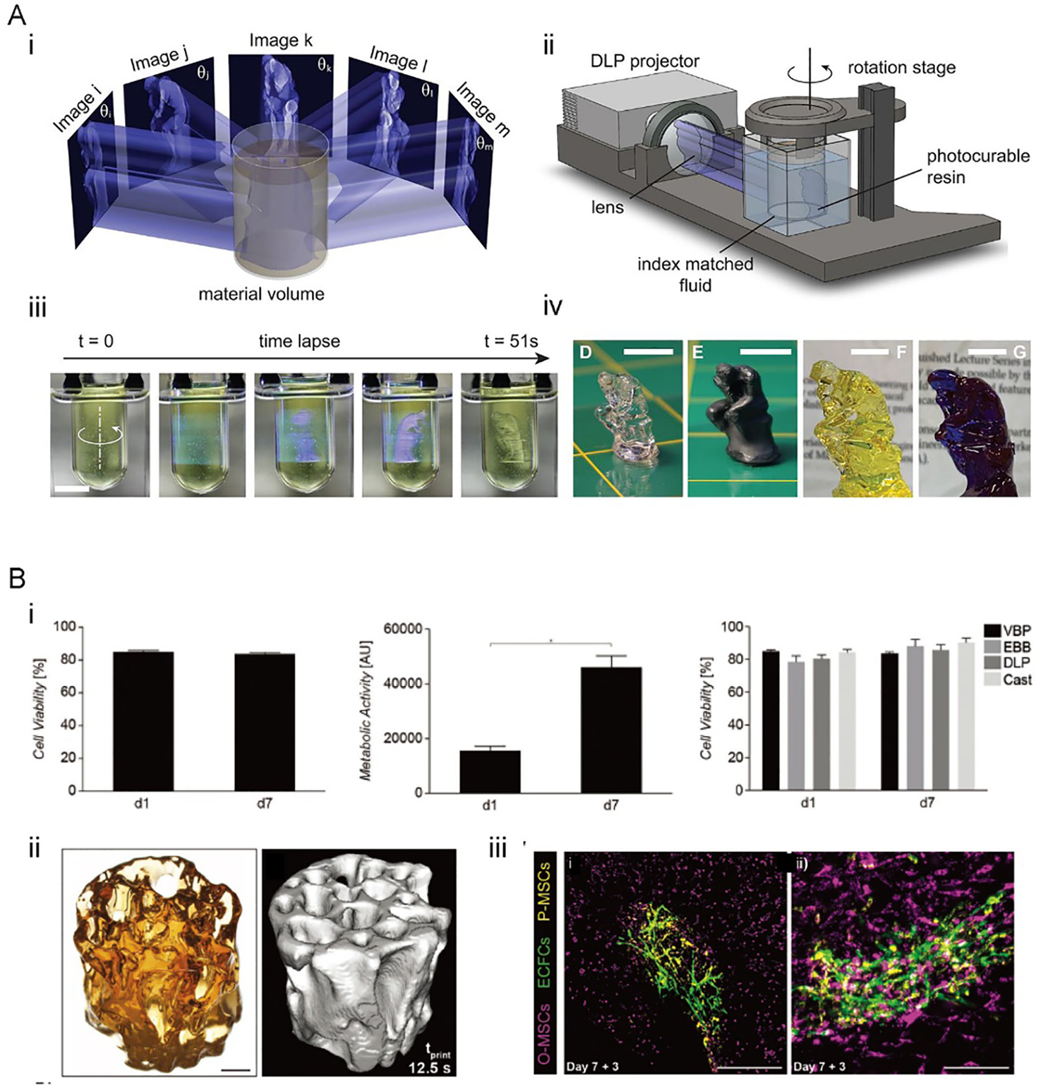
A) The CAL volumetric printing method. i) Principle of the CAL volumetric printing. ii) Schematic of the volumetric CAL printer setup. iii) Time-lapse photographs showing the printing process. iv) 3D-printed constructs of different sizes after rinsing and drying. Reproduced with permission.[75] B) The volumetric tomographic bioprinting. i) Viability of the bioprinted articular chondroprogenitor cells (ACPCs) after 7 days of culturing. ii) 3D model and micro-CT image of a bioprinted bone model. iii) Human endothelial colony-forming progenitor cells[26] and MSCs (yellow) cultured on the printed bone induced capillary formation. Reproduced with permission.[77]
By using CAL and a photosensitive ink (bisphenol a glycerolate (1 glycerol/phenol)-diacrylate (BPAGDA) mixed with PEGDA in 75:25 wt.%), a centimeter-scaled structure could be fabricated within as little of 1 min, which indicates the fast printing feature of the method (Figure 10A iii and iv).[75] Significantly, the printing time for this method is not bound by the size of the model, unlike layer-by-layer methods. A model scaled two or three times will maintain the same printing time as long as a stronger light source is provided. In extrusion techniques, printing time increases cubically according to the scaling factor.[76] Structures in various geometries were achieved using the CAL printing, such as a lattice scaffold with detailed features of 0.3 mm in resolution and internal voids if around 1 mm, and bridges without supporting that presented distances of up to 25 mm.[75]
The volumetric tomographic printing solves many of the challenges of current bioprinting techniques, and its ability to produce microstructures with high cell viability in a matter of seconds bring promising advancements to bioprinting and its applications (Figure 10B).[77] Additionally, a low photoinitiator concentration of 0.037 wt.% LAP was required to produce precise structures, reducing the potential cytotoxicity risks correlated with higher concentrations of photoinitiator used in typical SLA-based bioprinting. Constructs are generated at a high-volume accuracy with a variation of 5.71 ± 2.31%, when comparing with its model. The resolution of these methods depends on optical and chemical aspects. The optical resolution of projected patterns relies on the pixel sizes which were 22.8 μm in this paper, but the focus depth limited the optical resolution to 33 μm at the edge of the container. Moreover, properties of printed materials can influence the printing resolution, for example, the resolution is decreased by the diffusion of chemicals. With this printing system, constructs with minimum resolvable feature sizes of 144.69 ± 13.55 μm were fabricated, and the perfusable channels with an inner diameter of 200 μm were produced.[77]
The unique features of such a volumetric tomographic printing technique further provide more freedom of design that cannot be obtained with current VP-based bioprinting techniques, such as the construction of movable parts. In one example, a ball-and-cage like a fluidic valve was printed[77] which may find potential applications in hydrodynamic-actuated soft robots and hydrogel-based microfluidics. These unique benefits of volumetric tomographic printing contribute to a variety of enabling applications in regenerative medicine, disease modeling, soft robotics, and medical devices.
3. Future prospective
The VP printing techniques provide faster building times and overall high resolutions for 3D bioprinting; nevertheless, some limitations hinder its full transition to biomedical applications. Recent advances have improved the formulations of bioinks used for SLA-based bioprinting, promoted the capacities (CLIP, HARP, and volumetric tomographic printing) to increase printing speeds, and applied multi-material strategies to pattern heterogeneous components. Even though these technologies have paved avenues for many new opportunities and provide a promising way of complex and personalized biomedical printing, efforts are still needed for them to be widely adopted to use in biomedicine.
For instance, SLA has been used to fabricate medical devices for applications in drug delivery, diagnostic testing, surgical assistance, and medical implants.[78–81] SLA-printed microneedles are degradable, and they could be loaded with anti-inflammatory drugs and anti-microbial agents to achieve transdermal drug delivery and anti-infection.[82] SLA was also used to produced hollow microneedles, where carbon nanofibers were incorporated for the detection of biomarkers.[83]
On the other hand, VP printing also rises as a collection of enabling approaches to build functional tissues and microscale tissue models. Biocompatible and biodegradable hydrogels have been used in preparing tissue scaffolds with SLA-based bioprinting.[9, 84–87] A dilemma lies in that, materials with lower stiffness are generally known as more cell-active in 3D bioprinting of soft tissues, but the layer-by-layer bioprinting nature of SLA/DLP requests stronger materials to achieve robust and high-resolution constructs, which hinders the application of the method in bioprinting. It is therefore further desired to develop new classes of bioinks or through adding additives. Likely a combination of both precise and rapid VP-based bioprinting techniques and bioinks optimized for each of the strategy, would lead to truly capable tissue bioprinting.[69]
Moreover, cell viability is reduced as printing times increases. CLIP, HARP, VPIP, and volumetric tomographic printing have the potential to tackle this issue due to their fast printing speeds. However, further studies are required to determine the influence of how the illumination parameters (e.g., strong light/laser power) and mechanical forces (e.g., with the flow layer) on not only the cell viability but also their functions during and post-bioprinting. Again, we anticipate significant efforts to be exerted on bringing these state-of-the-art VP-based or VP-like 3D printing techniques into bioprinting, through meticulous investigations into seamless integration of the hardware, software, bioink, and bioprinting conditions in a technique-specific manner.
The advantage of using clinical imaging data as the patterns makes VP a promising method for personalized medicine. As an example, the operation time and risk of surgery can be reduced with the help of patient-specific models fabricated.[88, 89] The model from x-ray CT was used to make a pulmonary heart valve using a thermoplastic elastomer with SLA, and its function was tested in a bioreactor.[90] MRI images scanned from patients was also applied to preparing vascular conduits with polyglycolic acid (PGA) coated by poly-4-hydroxybutyrate.[79, 91] The adoption of the same concept to the newly developed rapid and/or volumetric VP printing method would further promote their capacities in 3D printing/bioprinting in generating patient-specific devices and tissues.
Table 1.
Biomaterial inks used in DLP/SLA bioprinting.
| Material | Method | Wavelength | Photo-initiator | Cell | Application | Reference |
|---|---|---|---|---|---|---|
| PEGDA | DLP | Visible light | LAP | hASCs | Tissue modeling | [92] |
| DLP | 365 nm | LAP | HUVECs | Tissue modeling | [93] | |
| PVA-MA+GelMA | DLP | 450nm | Ru/SPS | hMSCs ACPCs | New bioink | [37] |
| GelMA | DLP | 500–550nm | Eosin Y, TEA, NVP | NIH/3T3 | Microscale cell patterning | [49] |
| DLP | Blue light | LAP | hHSCs | Hepatic tissue modeling | [94] | |
| GelMA+PEGDA | DLP | 405 nm | LAP | hMSCs | Vascular modeling | [26] |
| DLP | 405 nm | Eosin Y, TEA, NVP | NIH/3T3 | Microscale cell patterning | [82] | |
| GelAGE | DLP | Visible light | Ru/SPS | HACs | Tissue modeling | [50] |
| HAMA+GelMA | DLP | 365 nm | LAP | hiPSC-HPCs | Hepatic tissue modeling | [71] |
| DLP | 365 nm | LAP | HUVECs | Vascular modeling | [53] | |
| PDLLA-PEG/HA | DLP | Visible light | LAP | hASCs | Cartilage tissue modeling | [95] |
| Sil-MA | DLP | 365 nm | LAP | Human chondrocyte | Cartilage tissue modeling | [55] |
ACPCs: adult cardiac progenitor cells; GelMA: gelatin methacryloyl; GelAGE: allylated gelatin; HAMA: methacrylated hyaluronic acid; LAP: lithium phenyl-2,4,6-trimethylbenzoylphosphinate; NVP: 1-vinyl-2 pyrrolidinone; HACs: human articular chondrocytes; hASCs: human adipose derived stem cells; hHSCs: human hematopoietic stem cells; hiPSC-HPCs: hiPSC-derived hepatic progenitor cells; hMSCs: human mesenchymal stem cells; HUVECs: human umbilical vein endothelial cells; PEGDA: poly(ethylene glycol) diacrylate; PDLLA-PEG/HA: poly(D,L-lactic acid)/poly(ethylene glycol)/hyaluronic acid; PVA: poly(vinyl alcohol); Ru/SPS: tris(2,2’-bipyridyl)dichloro-ruthenium(II) hexahydrate/sodium persulfate; Sil-MA: methacrylated silk; TEA: triethanolamine.
Acknowledgments
This work was supported by funding from the National Institutes of Health (R00CA201603, R21EB025270, R21EB026175, R01EB028143, R03EB027984), the Brigham Research Institute, and the American Heart Association. We further thank Ami Lesha for proof-reading the manuscript.
References
- [1].Chartrain NA, Williams CB, Whittington AR, A review on fabricating tissue scaffolds using vat photopolymerization, Acta Biomater 74 (2018) 90–111. [DOI] [PubMed] [Google Scholar]
- [2].Gibson I, Rosen D, Stucker B, Vat photopolymerization processes, Additive Manufacturing Technologies, Springer; 2015, pp. 63–106. [Google Scholar]
- [3].Ng WL, Lee JM, Zhou M, Chen YW, Lee KA, Yeong WY, Shen YF, Vat polymerization-based bioprinting-process, materials, applications and regulatory challenges, Biofabrication 12(2) (2020) 022001. [DOI] [PubMed] [Google Scholar]
- [4].Patrício TF, Pereira RF, Cerva A, Bártolo PJ, Vat polymerization techniques for biotechnology and medicine, High Value Manufacturing: Advanced Research in Virtual and Rapid Prototyping: Proceedings of the 6th International Conference on Advanced Research in Virtual and Rapid Prototyping, Leiria, Portugal, 1–5 October, 2013, CRC Press, 2013, p. 203. [Google Scholar]
- [5].Bajaj P, Chan V, Jeong JH, Zorlutuna P, Kong H, Bashir R, 3-D biofabrication using stereolithography for biology and medicine, Conf Proc IEEE Eng Med Biol Soc 2012 (2012) 6805–8. [DOI] [PubMed] [Google Scholar]
- [6].Skoog SA, Goering PL, Narayan RJ, Stereolithography in tissue engineering, J Mater Sci Mater Med 25(3) (2014) 845–56. [DOI] [PubMed] [Google Scholar]
- [7].Melchels FP, Feijen J, Grijpma DW, A review on stereolithography and its applications in biomedical engineering, Biomaterials 31(24) (2010) 6121–30. [DOI] [PubMed] [Google Scholar]
- [8].Hagiwara T, Recent progress of photo‐resin for rapid prototyping,“resin for stereolithography”, Macromolecular Symposia, Wiley Online Library, 2001, pp. 397–402. [Google Scholar]
- [9].Cooke MN, Fisher JP, Dean D, Rimnac C, Mikos AG, Use of stereolithography to manufacture critical-sized 3D biodegradable scaffolds for bone ingrowth, J Biomed Mater Res B Appl Biomater 64(2) (2003) 65–9. [DOI] [PubMed] [Google Scholar]
- [10].Gauvin R, Chen YC, Lee JW, Soman P, Zorlutuna P, Nichol JW, Bae H, Chen S, Khademhosseini A, Microfabrication of complex porous tissue engineering scaffolds using 3D projection stereolithography, Biomaterials 33(15) (2012) 3824–34. [DOI] [PMC free article] [PubMed] [Google Scholar]
- [11].Lee KW, Wang S, Fox BC, Ritman EL, Yaszemski MJ, Lu L, Poly(propylene fumarate) bone tissue engineering scaffold fabrication using stereolithography: effects of resin formulations and laser parameters, Biomacromolecules 8(4) (2007) 1077–84. [DOI] [PubMed] [Google Scholar]
- [12].Lu Y, Mapili G, Suhali G, Chen S, Roy K, A digital micro-mirror device-based system for the microfabrication of complex, spatially patterned tissue engineering scaffolds, J Biomed Mater Res A 77(2) (2006) 396–405. [DOI] [PubMed] [Google Scholar]
- [13].Shiraishi I, Kajiyama Y, Yamagishi M, Hamaoka K, Images in cardiovascular medicine. Stereolithographic biomodeling of congenital heart disease by multislice computed tomography imaging, Circulation 113(17) (2006) e733–4. [DOI] [PubMed] [Google Scholar]
- [14].Mondschein RJ, Kanitkar A, Williams CB, Verbridge SS, Long TE, Polymer structure-property requirements for stereolithographic 3D printing of soft tissue engineering scaffolds, Biomaterials 140 (2017) 170–188. [DOI] [PubMed] [Google Scholar]
- [15].Popov VK, Evseev AV, Ivanov AL, Roginski VV, Volozhin AI, Howdle SM, Laser stereolithography and supercritical fluid processing for custom-designed implant fabrication, J Mater Sci Mater Med 15(2) (2004) 123–8. [DOI] [PubMed] [Google Scholar]
- [16].Northen TR, Brune DC, Woodbury NW, Synthesis and characterization of peptide grafted porous polymer microstructures, Biomacromolecules 7(3) (2006) 750–4. [DOI] [PubMed] [Google Scholar]
- [17].Bens A, Seitz H, Bermes G, Emons M, Pansky A, Roitzheim B, Tobiasch E, Tille C, Non‐toxic flexible photopolymers for medical stereolithography technology, Rapid Prototyping Journal (2007). [Google Scholar]
- [18].Ji S, Guvendiren M, Recent advances in bioink design for 3D bioprinting of tissues and organs, Frontiers in bioengineering and biotechnology 5 (2017) 23. [DOI] [PMC free article] [PubMed] [Google Scholar]
- [19].Jose RR, Rodriguez MJ, Dixon TA, Omenetto F, Kaplan DL, Evolution of bioinks and additive manufacturing technologies for 3D bioprinting, ACS biomaterials science & engineering 2(10) (2016) 1662–1678. [DOI] [PubMed] [Google Scholar]
- [20].Mizutani M, Matsuda T, Liquid acrylate‐endcapped biodegradable poly (ϵ‐caprolactone‐co‐trimethylene carbonate). I. Preparation and visible light‐induced photocuring characteristics, Journal of Biomedical Materials Research: An Official Journal of The Society for Biomaterials, The Japanese Society for Biomaterials, and The Australian Society for Biomaterials and the Korean Society for Biomaterials 62(3) (2002) 387–394. [DOI] [PubMed] [Google Scholar]
- [21].Matsuda T, Mizutani M, Liquid acrylate‐endcapped biodegradable poly (ϵ‐caprolactone‐co‐trimethylene carbonate). II. Computer‐aided stereolithographic microarchitectural surface photoconstructs, Journal of Biomedical Materials Research: An Official Journal of The Society for Biomaterials, The Japanese Society for Biomaterials, and The Australian Society for Biomaterials and the Korean Society for Biomaterials 62(3) (2002) 395–403. [DOI] [PubMed] [Google Scholar]
- [22].Rabinow BE, Nanosuspensions in drug delivery, Nat. Rev. Drug Discov 3(9) (2004) 785–796. [DOI] [PubMed] [Google Scholar]
- [23].Ezrailson EG, Olson MO, Guetzow KA, Busch H, Phosphorylation of non-histone chromatin proteins in normal and regenerating rat liver, Novikoff hepatoma and rat heart, FEBS Lett. 62(1) (1976) 69–73. [DOI] [PubMed] [Google Scholar]
- [24].Ligon SC, Liska R, Stampfl J, Gurr M, Mulhaupt R, Polymers for 3D Printing and Customized Additive Manufacturing, Chem Rev 117(15) (2017) 10212–10290. [DOI] [PMC free article] [PubMed] [Google Scholar]
- [25].Cavallo A, Madaghiele M, Masullo U, Lionetto MG, Sannino A, Photo‐crosslinked poly (ethylene glycol) diacrylate (PEGDA) hydrogels from low molecular weight prepolymer: swelling and permeation studies, Journal of Applied Polymer Science 134(2) (2017). [Google Scholar]
- [26].Grigoryan B, Paulsen SJ, Corbett DC, Sazer DW, Fortin CL, Zaita AJ, Greenfield PT, Calafat NJ, Gounley JP, Ta AH, Johansson F, Randles A, Rosenkrantz JE, Louis-Rosenberg JD, Galie PA, Stevens KR, Miller JS, Multivascular networks and functional intravascular topologies within biocompatible hydrogels, Science 364(6439) (2019) 458–464. [DOI] [PMC free article] [PubMed] [Google Scholar]
- [27].Morris VB, Nimbalkar S, Younesi M, McClellan P, Akkus O, Mechanical properties, cytocompatibility and manufacturability of chitosan: PEGDA hybrid-gel scaffolds by stereolithography, Annals of biomedical engineering 45(1) (2017) 286–296. [DOI] [PubMed] [Google Scholar]
- [28].Zhu J, Beamish JA, Tang C, Kottke-Marchant K, Marchant RE, Extracellular matrix-like cell-adhesive hydrogels from RGD-containing poly (ethylene glycol) diacrylate, Macromolecules 39(4) (2006) 1305–1307. [Google Scholar]
- [29].Sugiura S, Edahiro J.-i., Sumaru K, Kanamori T, Surface modification of polydimethylsiloxane with photo-grafted poly (ethylene glycol) for micropatterned protein adsorption and cell adhesion, Colloids and Surfaces B: Biointerfaces 63(2) (2008) 301–305. [DOI] [PubMed] [Google Scholar]
- [30].Chan V, Zorlutuna P, Jeong JH, Kong H, Bashir R, Three-dimensional photopatterning of hydrogels using stereolithography for long-term cell encapsulation, Lab on a Chip 10(16) (2010) 2062–2070. [DOI] [PubMed] [Google Scholar]
- [31].Chan V, Jeong JH, Bajaj P, Collens M, Saif T, Kong H, Bashir R, Multi-material bio-fabrication of hydrogel cantilevers and actuators with stereolithography, Lab on a Chip 12(1) (2012) 88–98. [DOI] [PubMed] [Google Scholar]
- [32].Huang X, Hou Y, Zhong L, Huang D, Qian H, Karperien M, Chen W, Promoted Chondrogenesis of Cocultured Chondrocytes and Mesenchymal Stem Cells under Hypoxia Using In-situ Forming Degradable Hydrogel Scaffolds, Biomacromolecules 19(1) (2018) 94–102. [DOI] [PubMed] [Google Scholar]
- [33].Yuan F, Ma M, Lu L, Pan Z, Zhou W, Cai J, Luo S, Zeng W, Yin F, Preparation and properties of polyvinyl alcohol (PVA) and hydroxylapatite (HA) hydrogels for cartilage tissue engineering, Cell Mol Biol (Noisy-le-grand) 63(5) (2017) 32–35. [DOI] [PubMed] [Google Scholar]
- [34].Oh SH, An DB, Kim TH, Lee JH, Wide-range stiffness gradient PVA/HA hydrogel to investigate stem cell differentiation behavior, Acta Biomater 35 (2016) 23–31. [DOI] [PubMed] [Google Scholar]
- [35].Lim KS, Kundu J, Reeves A, Poole-Warren LA, Kundu SC, Martens PJ, The influence of silkworm species on cellular interactions with novel PVA/silk sericin hydrogels, Macromol Biosci 12(3) (2012) 322–32. [DOI] [PubMed] [Google Scholar]
- [36].Chong SF, Smith AA, Zelikin AN, Microstructured, functional PVA hydrogels through bioconjugation with oligopeptides under physiological conditions, Small 9(6) (2013) 942–50. [DOI] [PubMed] [Google Scholar]
- [37].Lim KS, Levato R, Costa PF, Castilho MD, Alcala-Orozco CR, van Dorenmalen KMA, Melchels FPW, Gawlitta D, Hooper GJ, Malda J, Woodfield TBF, Bio-resin for high resolution lithography-based biofabrication of complex cell-laden constructs, Biofabrication 10(3) (2018) 034101. [DOI] [PubMed] [Google Scholar]
- [38].Carletti E, Motta A, Migliaresi C, Scaffolds for tissue engineering and 3D cell culture, Methods Mol Biol 695 (2011) 17–39. [DOI] [PubMed] [Google Scholar]
- [39].Bardakova KN, Akopova TA, Kurkov AV, Goncharuk GP, Butnaru DV, Burdukovskii VF, Antoshin AA, Farion IA, Zharikova TM, Shekhter AB, Yusupov VI, Timashev PS, Rochev YA, From Aggregates to Porous Three-Dimensional Scaffolds through a Mechanochemical Approach to Design Photosensitive Chitosan Derivatives, Mar Drugs 17(1) (2019). [DOI] [PMC free article] [PubMed] [Google Scholar]
- [40].Akopova TA, Demina TS, Cherkaev GV, Khavpachev MA, Bardakova KN, Grachev AV, Vladimirov LV, Zelenetskii AN, Timashev PS, Solvent-free synthesis and characterization of allyl chitosan derivatives, RSC advances 9(36) (2019) 20968–20975. [DOI] [PMC free article] [PubMed] [Google Scholar]
- [41].Ahmadi F, Oveisi Z, Samani SM, Amoozgar Z, Chitosan based hydrogels: characteristics and pharmaceutical applications, Res Pharm Sci 10(1) (2015) 1–16. [PMC free article] [PubMed] [Google Scholar]
- [42].Shao L, Gao Q, Xie C, Fu J, Xiang M, He Y, Directly coaxial 3D bioprinting of large-scale vascularized tissue constructs, Biofabrication (2020). [DOI] [PubMed] [Google Scholar]
- [43].Chen P, Zheng L, Wang Y, Tao M, Xie Z, Xia C, Gu C, Chen J, Qiu P, Mei S, Ning L, Shi Y, Fang C, Fan S, Lin X, Desktop-stereolithography 3D printing of a radially oriented extracellular matrix/mesenchymal stem cell exosome bioink for osteochondral defect regeneration, Theranostics 9(9) (2019) 2439–2459. [DOI] [PMC free article] [PubMed] [Google Scholar]
- [44].Xie M, Gao Q, Zhao H, Nie J, Fu Z, Wang H, Chen L, Shao L, Fu J, Chen Z, He Y, Electro-Assisted Bioprinting of Low-Concentration GelMA Microdroplets, Small 15(4) (2019) e1804216. [DOI] [PubMed] [Google Scholar]
- [45].Ying GL, Jiang N, Maharjan S, Yin YX, Chai RR, Cao X, Yang JZ, Miri AK, Hassan S, Zhang YS, Aqueous Two-Phase Emulsion Bioink-Enabled 3D Bioprinting of Porous Hydrogels, Adv Mater 30(50) (2018) e1805460. [DOI] [PMC free article] [PubMed] [Google Scholar]
- [46].Loessner D, Meinert C, Kaemmerer E, Martine LC, Yue K, Levett PA, Klein TJ, Melchels FP, Khademhosseini A, Hutmacher DW, Functionalization, preparation and use of cell-laden gelatin methacryloyl-based hydrogels as modular tissue culture platforms, Nat Protoc 11(4) (2016) 727–46. [DOI] [PubMed] [Google Scholar]
- [47].Yue K, Li X, Schrobback K, Sheikhi A, Annabi N, Leijten J, Zhang W, Zhang YS, Hutmacher DW, Klein TJ, Khademhosseini A, Structural analysis of photocrosslinkable methacryloyl-modified protein derivatives, Biomaterials 139 (2017) 163–171. [DOI] [PMC free article] [PubMed] [Google Scholar]
- [48].Ying G, Jiang N, Yu C, Zhang YS, Three-dimensional bioprinting of gelatin methacryloyl (GelMA), Bio-Design and Manufacturing 1(4) (2018) 215–224. [Google Scholar]
- [49].Wang Z, Kumar H, Tian Z, Jin X, Holzman JF, Menard F, Kim K, Visible Light Photoinitiation of Cell-Adhesive Gelatin Methacryloyl Hydrogels for Stereolithography 3D Bioprinting, ACS Appl Mater Interfaces 10(32) (2018) 26859–26869. [DOI] [PubMed] [Google Scholar]
- [50].Bertlein S, Brown G, Lim KS, Jungst T, Boeck T, Blunk T, Tessmar J, Hooper GJ, Woodfield TBF, Groll J, Thiol-Ene Clickable Gelatin: A Platform Bioink for Multiple 3D Biofabrication Technologies, Adv Mater 29(44) (2017). [DOI] [PubMed] [Google Scholar]
- [51].Poldervaart MT, Goversen B, de Ruijter M, Abbadessa A, Melchels FPW, Oner FC, Dhert WJA, Vermonden T, Alblas J, 3D bioprinting of methacrylated hyaluronic acid (MeHA) hydrogel with intrinsic osteogenicity, PLoS One 12(6) (2017) e0177628. [DOI] [PMC free article] [PubMed] [Google Scholar]
- [52].Lam T, Dehne T, Kruger JP, Hondke S, Endres M, Thomas A, Lauster R, Sittinger M, Kloke L, Photopolymerizable gelatin and hyaluronic acid for stereolithographic 3D bioprinting of tissue-engineered cartilage, J Biomed Mater Res B Appl Biomater 107(8) (2019) 2649–2657. [DOI] [PMC free article] [PubMed] [Google Scholar]
- [53].Zhu W, Qu X, Zhu J, Ma X, Patel S, Liu J, Wang P, Lai CS, Gou M, Xu Y, Zhang K, Chen S, Direct 3D bioprinting of prevascularized tissue constructs with complex microarchitecture, Biomaterials 124 (2017) 106–115. [DOI] [PMC free article] [PubMed] [Google Scholar]
- [54].Ashammakhi N, Ahadian S, Pountos I, Hu SK, Tellisi N, Bandaru P, Ostrovidov S, Dokmeci MR, Khademhosseini A, In situ three-dimensional printing for reparative and regenerative therapy, Biomed Microdevices 21(2) (2019) 42. [DOI] [PubMed] [Google Scholar]
- [55].Kim SH, Yeon YK, Lee JM, Chao JR, Lee YJ, Seo YB, Sultan MT, Lee OJ, Lee JS, Yoon SI, Hong IS, Khang G, Lee SJ, Yoo JJ, Park CH, Publisher Correction: Precisely printable and biocompatible silk fibroin bioink for digital light processing 3D printing, Nat Commun 9(1) (2018) 2350. [DOI] [PMC free article] [PubMed] [Google Scholar]
- [56].Wang J-C, Ruilova M, Lin Y-H, The development of an active separation method for bottom-up stereolithography system, 2017 IEEE/SICE International Symposium on System Integration (SII), IEEE, 2017, pp. 108–114. [Google Scholar]
- [57].Santoliquido O, Colombo P, Ortona A, Additive Manufacturing of ceramic components by Digital Light Processing: A comparison between the “bottom-up” and the “top-down” approaches, Journal of the European Ceramic Society 39(6) (2019) 2140–2148. [Google Scholar]
- [58].Ye H, Venketeswaran A, Das S, Zhou C, Investigation of separation force for constrained-surface stereolithography process from mechanics perspective, Rapid Prototyp J 23(4) (2017) 696–710. [Google Scholar]
- [59].Zhou C, Chen Y, Yang Z, Khoshnevis B, Development of multi-material mask-image-projection-based stereolithography for the fabrication of digital materials, Annual solid freeform fabrication symposium, Austin, TX, 2011, pp. 65–80. [Google Scholar]
- [60].Tumbleston JR, Shirvanyants D, Ermoshkin N, Janusziewicz R, Johnson AR, Kelly D, Chen K, Pinschmidt R, Rolland JP, Ermoshkin A, Samulski ET, DeSimone JM, Additive manufacturing. Continuous liquid interface production of 3D objects, Science 347(6228) (2015) 1349–52. [DOI] [PubMed] [Google Scholar]
- [61].Bao G, Suresh S, Cell and molecular mechanics of biological materials, Nat. Mater 2(11) (2003) 715–725. [DOI] [PubMed] [Google Scholar]
- [62].Walker DA, Hedrick JL, Mirkin CA, Rapid, large-volume, thermally controlled 3D printing using a mobile liquid interface, Science 366(6463) (2019) 360–364. [DOI] [PMC free article] [PubMed] [Google Scholar]
- [63].Liu W, Zhang YS, Heinrich MA, De Ferrari F, Jang HL, Bakht SM, Alvarez MM, Yang J, Li YC, Trujillo-de Santiago G, Miri AK, Zhu K, Khoshakhlagh P, Prakash G, Cheng H, Guan X, Zhong Z, Ju J, Zhu GH, Jin X, Shin SR, Dokmeci MR, Khademhosseini A, Rapid Continuous Multimaterial Extrusion Bioprinting, Adv Mater 29(3) (2017). [DOI] [PMC free article] [PubMed] [Google Scholar]
- [64].Rocca M, Fragasso A, Liu W, Heinrich MA, Zhang YS, Embedded Multimaterial Extrusion Bioprinting, SLAS Technol 23(2) (2018) 154–163. [DOI] [PMC free article] [PubMed] [Google Scholar]
- [65].Skylar-Scott MA, Mueller J, Visser CW, Lewis JA, Voxelated soft matter via multimaterial multinozzle 3D printing, Nature 575(7782) (2019) 330–335. [DOI] [PubMed] [Google Scholar]
- [66].Maruo S, Ikuta K, Ninagawa T, Multi-polymer microstereolithography for hybrid opto-MEMS, Technical Digest. MEMS 2001. 14th IEEE International Conference on Micro Electro Mechanical Systems (Cat. No. 01CH37090), IEEE, 2001, pp. 151–154. [Google Scholar]
- [67].Ge Q, Sakhaei AH, Lee H, Dunn CK, Fang NX, Dunn ML, Multimaterial 4D Printing with Tailorable Shape Memory Polymers, Sci Rep 6 (2016) 31110. [DOI] [PMC free article] [PubMed] [Google Scholar]
- [68].Han LH, Suri S, Schmidt CE, Chen S, Fabrication of three-dimensional scaffolds for heterogeneous tissue engineering, Biomed Microdevices 12(4) (2010) 721–5. [DOI] [PubMed] [Google Scholar]
- [69].Arcaute K, Mann BK, Wicker RB, Practical use of hydrogels in stereolithography for tissue engineering applications, Stereolithography, Springer; 2011, pp. 299–331. [Google Scholar]
- [70].Inamdar A, Magana M, Medina F, Grajeda Y, Wicker R, Development of an automated multiple material stereolithography machine, Proceedings of Annual Solid Freeform Fabrication Symposium, 2006, pp. 624–635. [Google Scholar]
- [71].Ma X, Qu X, Zhu W, Li YS, Yuan S, Zhang H, Liu J, Wang P, Lai CS, Zanella F, Feng GS, Sheikh F, Chien S, Chen S, Deterministically patterned biomimetic human iPSC-derived hepatic model via rapid 3D bioprinting, Proc Natl Acad Sci U S A 113(8) (2016) 2206–11. [DOI] [PMC free article] [PubMed] [Google Scholar]
- [72].Miri AK, Nieto D, Iglesias L, Goodarzi Hosseinabadi H, Maharjan S, Ruiz-Esparza GU, Khoshakhlagh P, Manbachi A, Dokmeci MR, Chen S, Shin SR, Zhang YS, Khademhosseini A, Microfluidics-Enabled Multimaterial Maskless Stereolithographic Bioprinting, Adv Mater 30(27) (2018) e1800242. [DOI] [PMC free article] [PubMed] [Google Scholar]
- [73].Schwartz JJ, Boydston AJ, Multimaterial actinic spatial control 3D and 4D printing, Nat Commun 10(1) (2019) 791. [DOI] [PMC free article] [PubMed] [Google Scholar]
- [74].de Beer MP, van der Laan HL, Cole MA, Whelan RJ, Burns MA, Scott TF, Rapid, continuous additive manufacturing by volumetric polymerization inhibition patterning, Sci Adv 5(1) (2019) eaau8723. [DOI] [PMC free article] [PubMed] [Google Scholar]
- [75].Kelly BE, Bhattacharya I, Heidari H, Shusteff M, Spadaccini CM, Taylor HK, Volumetric additive manufacturing via tomographic reconstruction, Science 363(6431) (2019) 1075–1079. [DOI] [PubMed] [Google Scholar]
- [76].Wang M, Favi P, Cheng X, Golshan NH, Ziemer KS, Keidar M, Webster TJ, Cold atmospheric plasma (CAP) surface nanomodified 3D printed polylactic acid (PLA) scaffolds for bone regeneration, Acta biomaterialia 46 (2016) 256–265. [DOI] [PubMed] [Google Scholar]
- [77].Bernal PN, Delrot P, Loterie D, Li Y, Malda J, Moser C, Levato R, Volumetric Bioprinting of Complex Living‐Tissue Constructs within Seconds, Advanced materials 31(42) (2019) 1904209. [DOI] [PubMed] [Google Scholar]
- [78].Naumann A, Aigner J, Staudenmaier R, Seemann M, Bruening R, Englmeier KH, Kadegge G, Pavesio A, Kastenbauer E, Berghaus A, Clinical aspects and strategy for biomaterial engineering of an auricle based on three-dimensional stereolithography, Eur Arch Otorhinolaryngol 260(10) (2003) 568–75. [DOI] [PubMed] [Google Scholar]
- [79].Sodian R, Fu P, Lueders C, Szymanski D, Fritsche C, Gutberlet M, Hoerstrup SP, Hausmann H, Lueth T, Hetzer R, Tissue engineering of vascular conduits: fabrication of custom-made scaffolds using rapid prototyping techniques, Thorac Cardiovasc Surg 53(3) (2005) 144–9. [DOI] [PubMed] [Google Scholar]
- [80].Moreno Madrid AP, Vrech SM, Sanchez MA, Rodriguez AP, Advances in additive manufacturing for bone tissue engineering scaffolds, Mater Sci Eng C Mater Biol Appl 100 (2019) 631–644. [DOI] [PubMed] [Google Scholar]
- [81].Derakhshanfar S, Mbeleck R, Xu K, Zhang X, Zhong W, Xing M, 3D bioprinting for biomedical devices and tissue engineering: A review of recent trends and advances, Bioact Mater 3(2) (2018) 144–156. [DOI] [PMC free article] [PubMed] [Google Scholar]
- [82].Boehm RD, Miller PR, Singh R, Shah A, Stafslien S, Daniels J, Narayan RJ, Indirect rapid prototyping of antibacterial acid anhydride copolymer microneedles, Biofabrication 4(1) (2012) 011002. [DOI] [PubMed] [Google Scholar]
- [83].Miller PR, Gittard SD, Edwards TL, Lopez DM, Xiao X, Wheeler DR, Monteiro-Riviere NA, Brozik SM, Polsky R, Narayan RJ, Integrated carbon fiber electrodes within hollow polymer microneedles for transdermal electrochemical sensing, Biomicrofluidics 5(1) (2011) 13415. [DOI] [PMC free article] [PubMed] [Google Scholar]
- [84].Jansen J, Melchels FP, Grijpma DW, Feijen J, Fumaric acid monoethyl ester-functionalized poly(D,L-lactide)/N-vinyl-2-pyrrolidone resins for the preparation of tissue engineering scaffolds by stereolithography, Biomacromolecules 10(2) (2009) 214–20. [DOI] [PubMed] [Google Scholar]
- [85].Melchels FP, Bertoldi K, Gabbrielli R, Velders AH, Feijen J, Grijpma DW, Mathematically defined tissue engineering scaffold architectures prepared by stereolithography, Biomaterials 31(27) (2010) 6909–6916. [DOI] [PubMed] [Google Scholar]
- [86].Cohen A, Laviv A, Berman P, Nashef R, Abu-Tair J, Mandibular reconstruction using stereolithographic 3-dimensional printing modeling technology, Oral Surgery, Oral Medicine, Oral Pathology, Oral Radiology, and Endodontology 108(5) (2009) 661–666. [DOI] [PubMed] [Google Scholar]
- [87].Zorlutuna P, Jeong JH, Kong H, Bashir R, Stereolithography‐based hydrogel microenvironments to examine cellular interactions, Advanced Functional Materials 21(19) (2011) 3642–3651. [Google Scholar]
- [88].Sarment DP, Al-Shammari K, Kazor CE, Stereolithographic surgical templates for placement of dental implants in complex cases, Int J Periodontics Restorative Dent 23(3) (2003) 287–95. [PubMed] [Google Scholar]
- [89].Binder TM, Moertl D, Mundigler G, Rehak G, Franke M, Delle-Karth G, Mohl W, Baumgartner H, Maurer G, Stereolithographic biomodeling to create tangible hard copies of cardiac structures from echocardiographic data: in vitro and in vivo validation, J Am Coll Cardiol 35(1) (2000) 230–7. [DOI] [PubMed] [Google Scholar]
- [90].Sodian R, Loebe M, Hein A, Martin DP, Hoerstrup SP, Potapov EV, Hausmann H, Lueth T, Hetzer R, Application of stereolithography for scaffold fabrication for tissue engineered heart valves, ASAIO J 48(1) (2002) 12–6. [DOI] [PubMed] [Google Scholar]
- [91].Undt G, Wild K, Reuther G, Ewers R, MRI-based stereolithographic models of the temporomandibular joint: technical innovation, Journal of Cranio-Maxillofacial Surgery 28(5) (2000) 258–263. [DOI] [PubMed] [Google Scholar]
- [92].Lin H, Zhang D, Alexander PG, Yang G, Tan J, Cheng AW-M, Tuan RS, Application of visible light-based projection stereolithography for live cell-scaffold fabrication with designed architecture, Biomaterials 34(2) (2013) 331–339. [DOI] [PMC free article] [PubMed] [Google Scholar]
- [93].Shanjani Y, Pan C, Elomaa L, Yang Y, A novel bioprinting method and system for forming hybrid tissue engineering constructs, Biofabrication 7(4) (2015) 045008. [DOI] [PubMed] [Google Scholar]
- [94].Grix T, Ruppelt A, Thomas A, Amler AK, Noichl BP, Lauster R, Kloke L, Bioprinting Perfusion-Enabled Liver Equivalents for Advanced Organ-on-a-Chip Applications, Genes (Basel) 9(4) (2018). [DOI] [PMC free article] [PubMed] [Google Scholar]
- [95].Sun AX, Lin H, Beck AM, Kilroy EJ, Tuan RS, Projection stereolithographic fabrication of human adipose stem cell-incorporated biodegradable scaffolds for cartilage tissue engineering, Frontiers in bioengineering and biotechnology 3 (2015) 115. [DOI] [PMC free article] [PubMed] [Google Scholar]