

Abstract
Objective.
To quantify relations between the neuronal activity recorded with chronically-implanted intracortical microelectrodes and the histology of the surrounding tissue, using radial distance from the tip sites and time after array implantation as parameters.
Approach.
‘Utah’-type intracortical microelectrode arrays were implanted into cats’ sensorimotor cortex for 275–364 days. The brain tissue around the implants was immuno-stained for the neuronal marker NeuN and for the astrocyte marker GFAP. Pearson’s product-moment correlations were used to quantify the relations between these markers and the amplitudes of the recorded neuronal action potentials (APs) and their signal-to-noise ratios (S/N).
Main results.
S/N was more stable over post-implant time than was AP amplitude, but its increased correlation with neuronal density after many months indicates ongoing loss of neurons around the microelectrodes. S/N was correlated with neuron density out to at least 140 μm from the microelectrodes, while AP amplitude was correlated with neuron density and GFAP density within ~80 μm. Correlations between AP amplitude and histology markers (GFAP and NeuN density) were strongest immediately after implantation, while correlation between the neuron density and S/N was strongest near the time the animals were sacrificed. Unlike AP amplitude, there was no significant correlation between S/N and density of GFAP around the tip sites.
Significance.
Our findings indicate an evolving interaction between changes in the tissue surrounding the microelectrodes and the microelectrode’s electrical properties. Ongoing loss of neurons around recording microelectrodes, and the interactions between their delayed electrical deterioration and early tissue scarring around the tips appear to pose the greatest threats to the microelectrodes’ long-term functionality.
Keywords: intracortical microelectrodes, chronic recording, neuronal activity, signal-to-noise ratio, correlation analysis, cats
1. Introduction
Many studies have characterized the tissue responses in the brain after implantation and chronic residence of penetrating microelectrodes [1-24] but there has been relatively few attempts to correlate the histologic changes induced by implantation and long-term residence of the microelectrodes with metrics of the recorded neural activity [5, 8, 25] McConnell et al [11] detected a positive correlation between the amount of astrocytic scarring around chronically implanted intracortical microelectrodes and the microelectrodes’ electrical impedance but it was unclear how the elevated impedance might affect the microelectrodes ability to record neuronal action potentials (APs). Biran et al [1] evaluated the histologic changes chronically-implanted silicon microelectrode arrays. They observed an elevation of glial cells numbers (both astrocytes and microglia) accompanied by a decrease in the number of neurons in the electrodes’ vicinity [38]. The development of this histological pattern was accompanied by a steady decrease in the signal-to-noise ratio of the recorded neuronal APs. This suggested that the glial response and cell loss impair neuronal recording over time. Freire et al [5] observed a significant correlation between the rate of recorded neuronal APs that could be recorded by chronically implanted intracortical microelectrodes (up to 20 weeks in the brain) and changes in several markers of the neuronal integrity. Kim et al [8] found a statistically significant correlation (Pearson’ s product-moment correlation (PPMC)) between the density of astrocyte processes around polyimide-based intracortical microelectrodes and the signal-to-noise ratio (S/N) of recorded APs. However, they did not find a significant correlation between S/N and neuronal density around the electrodes. Prasad and Sanchez [15] determined that neuronal APs were best detected (best-signal-to noise ratio) when the impedance of the intracortical microelectrodes was between 40 and 150 kΩ, suggesting an evolving interaction between the ‘biotic’ events in the surrounding tissue and the ‘abiotic’ properties of the recording microelectrodes. McConnell et al [26] described how persisting inflammation around chronically-implanted microelectrodes can lead to neuronal degeneration and death over a period of several months. Kane et al [27] measured the electrical impedance of the same microelectrodes used in the present study. They found a moderate continuing decrease in their impedance at 1 kHz over the first 300 days in vivo, which they attributed to development of defects in the electrodes’ electrical insulation that were seen by scanning electron microscopy after they were removed from the brains.
The present study was performed to help to clarify the relations between metrics of the quality of the neuronal recording by chronically implanted intracortical microelectrodes and the histologic changes that occur around the microelectrodes’ tip sites, and how these relations might evolve over time. Also, how these relations might be affected by slow changes in the electrical properties of the electrodes themselves. We correlated two predictor metrics (neuronal density and the density of GFAP labeling around each microelectrode’s tip site with two outcome metrics (amplitude and signal-to-noise ratios of recorded neuronal APs). We incorporated several procedures that had not been used in previous studies. For each microelectrode, the outcome metrics were measured close to the time the microelectrodes were implanted, and again just before the animals were sacrificed. We used radial distance from the electrode as a parameter in the quantitation of the predictor metrics and in the subsequent correlation analysis, and we normalized the histologic metrics (predictor metrics) on their values at the perimeter of the radius of measurement in order to emphasize their differences, across electrode sites, in the immediate vicinity of each microelectrode.
2. Methods
2.1. Implantation of microelectrode arrays, data acquisition, and quantitation of neuronal activity.
‘Utah’ intracortical arrays (Blackrock Microsystem, Inc.), each with 16 microelectrode shanks, were implanted into the post-cruciate gyrus (sensorimotor cortex) of young adult male domestic cats, as part of a study of the effect of neurotrophic coating on long-term neuronal recording [28]. The findings from that part of the study will be described in a forthcoming publication. The findings reported here are from four untreated arrays from four animals sacrificed 275–364 days after implantation (table 1), when a particular array began to exhibit signs of electrical failure, as indicated by a loss of electrical continuity to 2 or 3 previously functional channels. Neuronal activity was recorded each week, for 2 min, from all electrically-functional microelectrodes from which 50 or more APs min−1 could be recorded, using hardware and software of our own design and construction. In preparation for each session of neuronal recording, the animals were lightly anesthetized with a single I.M. Injection of 10 mg kg−1 of ketamine and 0.25 mg kg−1 of acepromazine.
Table 1.
Dates of implantation and number of days in vivo for the 4 microelectrode arrays used in the study.
| Animal | Array implant date |
Date of sacrifice | Days array implanted |
|---|---|---|---|
| Peg32 | 1 January 2011 | 1 December 2010 | 317 |
| Peg41 | 16 January 2010 | 28 October 2010 | 275 |
| Peg82 | 6 May 2010 | 6 May 2011 | 364 |
| Peg91 | 1 September 2010 | 15 July 2011 | 318 |
The recorded signals were analyzed offline using custom software written in QuickBasic (Microsoft). A bandpass of 400 Hz–4 KHz was used. The standard deviation (σ) of the amplitude of all of the peaks in the recorded signal from each microelectrode was calculated. Events ⩾3σ were considered to be neuronal APs. The standard deviation of the peak amplitudes was re-computed with events ⩾3σ omitted, and designated as the noise standard deviation (σn). The S/N for the recordings was computed as (mean AP amplitude)/σn. This computation was done separately for all APs with S/N ⩾ 3 and also for the largest 10% of APs with S/N ⩾ 3. When defined in this manner, a large S/N signifies that the relatively uncommon events that qualify as APs tend to be relatively large (in units of σn) when compared to the more numerous small event that are classified as Noise, while smaller S/N signifies a smaller relative difference, in units of σn. Next, the arithmetic means of the events classified as APs from 1, 2, and 3 weeks after array implantation were averaged (arithmetic means) to obtain estimates of the AP amplitudes and their S/N ratios close to the time of implantation of the arrays. This was separately done for each microelectrode. The same procedure was applied to the recordings obtained from the same microelectrodes during the last three weekly recording sessions ending on the day the animal was sacrificed. Henceforth, references to ‘AP amplitude’ or ‘S/N’ refer to these 3-day averages.
Samples of APs from one microelectrode and one recording session are shown in figure 1, with events ⩾3σ criteria indicated by *. However, as discussed in section 4.5, much of the activity with peak amplitudes is <3σ probably is small neuronal APs.
Figure 1.

Neuronal action potentials (*) recorded from intracortical microelectrode 1, 14 days after implanting the microelectrode array. The APs labeled ‘large’ and ‘mean’ are representative of the largest 10% of APs, and of all AP with (signal-to noise ratio ⩾3). The APs labeled ‘small’ are slightly above the threshold of detection.
At the time the animals were sacrificed we were able to record APs with S/N ⩾3 from 54 of the 64 microelectrodes in the 4 arrays. In preparation for histologic evaluation of the microelectrode sites, the animal were anesthetized with ketamine and perfused through the heart with 1.5 l of 0.9% saline followed by 1.5 l of 4% paraformaldehyde in phosphate-buffered saline. At necropsy we selected four intracortical arrays whose superstructures were level with the surrounding surface of the brain (not dislodged, tipped, or depressed), indicating that the array’s 16 tip sites were at approximately the same depth in the cortex. The dura mater and internal capsule covering the array was removed with the electrode array in situ. The array cable was cut close to the array and the array removed from the brain. The left rostral corner of the resected tissue block was trimmed diagonally to allow proper orientation of the histologic sections. The trimmed tissue block was mechanically stabilized and imbedded into paraffin using a custom apparatus, so that the histologic section from the microtome will be nearly perpendicular to the tracks of each of the 16 microelectrodes. The blocks were sectioned at a thickness of 10 μm. The paraffin sections that include the tip sites of the 54 functional microelectrodes were stained for GFAP, a marker for astrocytic processes (Dako Cytomation, Carpenteria, CA), and for the neuron marker NeuN (Chemicon, Tamecula, CA). The chromogen for the NeuN is NOVA RED SK-4800, (Vector Laboratories, Burlingame, CA) yielding a reddish brown reaction product, and Vector SG (Vector laboratories) for GFAP, yielding a blue-gray label (figure 2(A)). The immunostained sections were photographed with a 1600 × 1200 dpi digital camera.
Figure 2.

(A). Micrograph of the tissue surrounding the tip site (T) of a microelectrode implanted for 200 days. Cell bodies of neurons (N) are labeled with NeuN and the reddish-brown Vector Red chromophore are surrounded by the meshwork of astrocyte fibers labeled with GFAP and the blue chromophore Vector nickel) against the white background. The cell body of two fibrous astrocytes (a) are indicated. (B) Histogram of the number of neuronal profiles with centroids within 150 μm of the centers of 54 microelectrode tip sites from four microelectrode arrays (68 ± 16.8 neurons per site).
Figure 2(A) shows the neurons and astrocytes and the mesh of astrocyte processes against the white background. The brightness and RGB composition of each image pixel was determined, and pixels having a predominance of green and blue were assumed to be the GFAP label (versus a predominance of red, indicating NeuN labeling). Custom image analysis software (written in Visual Basic, Microsoft Inc., and incorporating the National Instruments Measurements Studio, National Instruments, Inc.) was used to compute the area of each enclosed NeuN-labeled profile and the distance from the centroid of each neuronal profile to the center of the electrode tip site. The smallest NeuN labeled profiles may represent very small neurons, or damaged neurons (or grazing cuts through a large neuron), and therefore the smallest 1/8 of the profiles were excluded from the subsequent analyses. After these exclusions, the location of the centroids and cross-sectional areas of 3733 neuronal profiles from the 54 tip sites was cataloged. The number of neuronal profiles per tip site varied from 27 to 100 (68 ± 16.8 neurons per tip site (figure 2(B)). The histology of the tissue surrounding the electrodes’ tip sites revealed variable amounts of neuronal loss and tissue damage surrounding the microelectrodes’ tip sites. Figure 3 shows histologic sections perpendicular to the microelectrodes’ shafts and through the tip sites of two microelectrodes, from cats sacrificed 318 and 275 days after implantation of the arrays. The tissue defect left by the microelectrode’s tip is indicated by an X. NeuN-labeled profiles (neuronal profiles) within 175 μm of the center of the tip sites were counted in two histologic sections through the tip site. The density of GFAP labeling versus distance from the center of each tip site was determined with the same software.
Figure 3.

(A), (B) Micrographs of the sites of the tips of two chronically-implanted intracortical microelectrodes. The ovoid profiles of neurons are labeled by the red-brown chromophore of the anti-NeuN antibody. The blue-black background is astrocyte processes labeled by the chromophore of the anti-GFAP antibody. The centers of the microelectrodes’ tip sites are indicated by (X), and the concentric circles indicate the inner (20 μm) and outer (175 μm) limits of the region within which neuron density and GFAP density was quantified. (A) is a tip site of a microelectrode with minimal scarring and mild astrocytosis (enhanced GFAP labeling) around the tip site. (B) is a tip site with more severe scarring around the tip site. The scar does not label with the GFAP antibody and appears as a translucency against the dark background of GFAP labeling, surrounded by a region of increased density of astrocyte processes. (C), (D) Sections from the tip sites of the same two microelectrodes, and stained with Masson’s tri-chrome, showing the spatial extent of the collagen-containing (fibrotic) scars (blue). The tissue sections for (C) and (D) are approximately 50 μm dorsal of (A) and (B), respectively. In (C), there is minimal collagenous fibrotic scarring around the tip site, while in (D) the more extensive scarring corresponds to the translucency against the background of GFAP staining shown in (B).
2.2. Data analysis
To quantify the correlations between the tissue responses around the microelectrodes (predictor metrics) and the AP amplitudes and signal-to-noise ratio (S/N) (outcome metrics), we adapted and expanded upon methods used by Freire et al [5], Kim et al [8] and McConnel et al [26]. We correlated two predictor metrics (neuronal density and the density of GFAP labeling around each microelectrode’s tip site) obtained at the time the animals were sacrificed, with outcome metrics (amplitude and signal-to-noise ratios of recorded neuronal APs) that were measured close to the time the microelectrodes were implanted, and also before the animals were sacrificed. The action potential amplitudes (AP amplitudes) and signal-to-noise ratios (SNR) were obtained from the same recordings of neuronal activity. These recording sessions began 1 week after implantation of the microelectrode arrays and ended on the day the animals were sacrificed. The histology upon which the calculations of neuronal density and GFAP density based are from the same animals (table 1) and the same electrode sites from which the neuronal activities were recorded.
The predictor metrics for neuron and GFAP density were computed within concentric overlapping annuli spanning a range of radial distances from the center of the microelectrode’s tip site (figure 4). The width of each annulus decreases with increasing radial distance from the tip site in order to maintain constant annulus area, and thus maintain constant statistical power of the correlation analysis across radial distance from the center of the tip sites. Larger annuli afford greater statistical power, but at the cost of reduced radial resolution of the predictor metrics, so the choice of the number of annuli and their area represents a compromise. For neurons, we chose six annuli, and the largest annulus (13 502 μm2) for which there would be no overlap between the two innermost (spanning 10 to ~95 μm) and outermost two annuli (spanning ~105 to 160 μm), allowing a fully independent determination of the correlations near versus far from the tip sites. For these two regions, the calculations of the correlations between predictor and outcome metrics is completely independent. The radial gradient of GFAP density is steep within 80 μm of the center of the tips (figure 5(B)), so for the quantitation of GFAP density we used eight annuli (6600 μm2) in order to provide independence of the correlations within 85 μm of the tip sites, versus the region spanning 95–160 μm. However, the variable width of the annuli does cause the radial resolution of the correlation analysis to vary with radial distance from the center of the tip site, and correlation coefficients from adjacent, overlapping annuli are not fully independent. However, they do convey some information regarding the radial gradient of the correlations.
Figure 4.

Segments of the overlapping annuli used to characterize the radial distribution of the centroids of neuronal profiles labeled with NeuN and the density of GFAP labeling of astrocyte processes around the tip of each of the 54 intracortical microelectrodes. Segments on the right side of the figure are for neurons, those on the left are for GFAP. Neuronal profiles whose centroids lie within an annulus are counted as lying within that annulus. Each annulus circumscribes the full circumference around the center of the tip site but for clarity, only segments of each annulus is shown. The region between 160 μm (full circle shown as broken line) annulus and 175 μm (solid bright circle) was used to normalized the neuron counts and the density of GFAP labeling within each of the overlapping annulus.
Figure 5.

(A) The means, standard errors (small error bars) and standard deviations (large error bars) of the density of 3733 neuronal profiles surrounding the tip sites of 54 intracortical microelectrodes. The densities were measured within concentric overlapping, equal-area annuli (13 500 μm2) around the tip sites whose centers are indicated on the abscissa. For each tip site, the neuronal counts were normalized on the area of the annulus within which they were measured, and then on the neuronal density within the annulus spanning 160–175 μm from the center of the tip site. (B) Density of GFAP labeling within concentric annuli of 6600 μm2 surrounding the 54 tip sites. For each site, the GFAP density within the annulus was normalized on the density within the annulus spanning 160–175 μm from the center of the tip site.
For each microelectrode, the (dimensionless) predictor for neuron density within an annulus is the density of NeuN-labeled profiles within the annulus normalized on the density of neuronal centroids within the annulus spanning 160–175 μm from the center of the same microelectrode site. For GFAP, the predictor metric is the density of the GFAP labeling within each annulus normalized on the density within the annulus spanning 160–175 μm from the center of the tip site.
The outcome metrics for the recorded neuronal activity from each microelectrode are the arithmetic means of the amplitudes of the recorded APs with S/N ⩾3, and the arithmetic means of their S/N, averaged over the first 3 weekly recording sessions (beginning 1 week after microelectrode implantation) and (a separate set of outcome metrics) from the recordings obtained during the 3 weekly recording sessions ending on the day the animals were sacrificed. Separate outcome metrics were calculated for all APs with S/N ⩾3 and also for the largest 10% of those AP from each recording session. PPMC coefficients (r) between the predictor and outcome metrics were calculated (Minitab 16 statistical software).
The data sets for the correlation analysis are the ensembles of predictor–outcome pairs, each member of a set being from the same microelectrode of the same intracortical array. Separate data sets were generated and PPMC calculated for each of the outcome metrics and for the normalized neurons counts and GFAP density within each of the overlapping annuli. r-values were computed using all APs with S/N ⩾3 as the outcome and separately, for the largest 10% of the same set of APs. Pearson’s PMC is sensitive to outliers, and assumes that the data are normally distributed, so the data were z-scored and outliers (values greater than 3σ from the means of the z-scored data, and constituting ~3%–4% of the data), were omitted from analysis. Prior to calculating the correlation coefficients, the remaining data were normalized by a Johnson’s transform [29]. The Pearson coefficient of determination (r2) represents the portion of the variance of the outcome metric that can be attributed to the variance of the predictor within each of the overlapping annuli, which we expressed as a percentage, r2 × 100.
Also, a single value of r2 × 100 was calculated for the entire radius of measurement (40–150 μm), with neuronal density and GFAP density normalized on their densities between 160 and 175 μm from the tip site. The correlation coefficients from annuli at different distances from the microelectrodes were compared for significant differences using Fisher’s z-test [29], and their r-values were considered to be significantly different for p-values < 0.02 in a 2-sided z-test, which controls the family-wise Type I error rate at 0.05 while allowing two comparisons between the correlation coefficients from the inner and outer regions. Also, an analysis of variances was performed by the Minitab software to estimate the level of significance (p) of the individual r-values.
Table 2 shows the coefficients of determination (r2 × 100%) for the correlations between the amplitude of the recorded APs or their S/Ns, and the normalized density of neurons surrounding the tip sites. The AP amplitudes and S/Ns are the averages of the values recorded from the corresponding microelectrode during the three recording sessions from the 2 weeks preceding sacrifice of the animals. The coefficients are 2–5 times greater when the densities are normalized to remove the influence of the more widespread differences in neuron density, and to minimize the contributions of other microelectrodes in the same array to the predictor metrics. These normalized neuron densities were used for all of the correlations shown in figures 7 and 8. Similarly, the normalized density GFAP labeling was used for the correlations shown in figure 9.
Table 2.
Coefficients of determination, expressed as r2 × 100%, for the Pearson product-moment correlations between neuronal density and each of the four outcome metrics listed in column 1. The neuronal activities used to compute the outcome metrics were recorded during the three sessions spanning 2 weeks before the animals were sacrificed. The neuron density surrounding each of the 54 tip sites was determined by dividing the number of neuronal profiles 20–150 μm from the centers of each tip site by the area of that region. In column 2, the neuron density so determined was divided by (normalized on) the neuron density within the annulus spanning 160–175 μm from the center of the tip site. In column 3, the neuron density (between 20 and 150 μm from the tip sites) was not normalized on the neuron density in the annulus spanning 160–175 μm from the center of the same electrode site.
| Outcome metric | r2 × 100% neuron density normalized | r2 × 100% neuron density not normalized |
|---|---|---|
| S/N, largest 10% of APs with S/N ⩾3 | 49.2% | 10% |
| S/N, all APs with S/N ⩾3 | 26% | 5% |
| Amplitude of largest 10% of APs | 67% | 34% |
| Amplitude of all APs w S/N ⩾3 | 57.8% | 15% |
Figure 7.
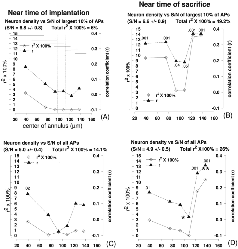
Pearson’s product-moment coefficients (r) and coefficients of determination (shown as 100% × r2) for the correlations between signal-to-noise ratio (S/N) of neuronal action potentials (APs) and neuron density within six overlapping 4300 μm2 annuli containing 3373 neurons surrounding 54 microelectrode tip sites from four intracortical microelectrode arrays. In (A), the approximate radial span of each of the seven annuli is indicated by the stepped sequence of horizontal lines. The annuli to the left of the left vertical broken line do not overlap with any of the annuli lying to the right of the right vertical broken line, so values of r and r2 within the left and right regions are statistically independent. The approximate level of significance (p) of each correlation coefficient for which p ⩽0.05 is shown above its symbol. r-values for unlabeled symbols are not significantly different from 0 (p ⩾0.05). In (D), r-values corresponding to symbols adjacent to (**) are significantly greater (p < 02) than those adjacent to (*), by Fisher’s z-test. The radial distances from the center of the electrode tip sites to the center of each annulus are shown on the abscissae. (A), (C) are from the recordings obtained 1, 2 and 3 weeks after array implantation, and (B), (D) are for the three recording sessions ending on the day the animals were sacrificed. The predictor and outcome metrics are listed above each graph, as is the mean and standard deviation of the S/N. The total r2 × 100% for the entire radius of measurement (40–140 μm) is an estimate of the % of the variance of the outcome metric that is explained by the predictor (see section 2 for details). (A), (B) show the largest 10% of the APs with S/N ⩾3 and (C), (D) show all APs with S/N ⩾3.
Figure 8.

Pearson’s product-moment coefficients and coefficients of determination for the correlations between neuron density and the amplitude of the same neuronal action potentials whose S/N is represented in figure 7. Details as for figure 7. (See section 2.1 for the definition of ‘AP amplitude’.)
Figure 9.

(A), (B) Pearson’s PM coefficient and coefficients of determination for the correlations between the normalized density of GFAP labeling and the signal-to-noise ratio (S/N) of the largest 10% of action potentials with S/N ⩾3. The data are from the same 54 intracortical microelectrodes represented in figures 7 and 8. (C), (D) shows the correlations for the amplitudes of the same AP represented in (A), (B), and (E), (F) for the amplitudes of all APs with S/N ⩾3. The measurements of normalized GFAP density are from eight overlapping 6600 μm2 annuli surrounding each microelectrode tip site. In panel (A), the approximate radial span of each of the eight annuli is indicated by the stepped array of horizontal lines.
3. Results
The histologic sections through the electrode sites revealed a circular defect left by each microelectrode’s tip (figures 3 and 4). The quantitative analysis of the histology revealed radial gradients of neuronal density and astrocytic processes surrounding the microelectrode sites. Figure 5(A) shows the radial gradient of the density of the 3733 NeuN-labeled profiles surrounding the 54 electrode sites. Similar loss of neurons around microelectrodes implanted chronically in the cerebral cortex have been described by many investigators [1, 3-7, 11-14, 17-19, 21-24]. Figure 5(B) shows the density of GFAP labeling around the 54 tip sites. The normalized density of GFAP labeling is reduced close to the tip sites and is slightly elevated between 80 and 120 μm from the center of the tip sites. Other investigators have described a similar response around microelectrodes implanted chronically in the cerebral cortex, in which the density of GFAP labeling is maximum 80–100 μm from the electrodes, then decreases to background at a distance of approximately 500 μm [1].
Figure 6(A) shows the third-order regression fits and the 95% confidence interval for the amplitudes of the APs recorded from the 54 microelectrodes, showing the trend during the first, middle and late portions of the first 275 days of implantation, at which time the first of the four animals was sacrificed. The regression plots of AP amplitude and AP S/N illustrate the trends over the first 275 days after implantation. Over the sample of 54 microelectrode sites, AP amplitude decreased slightly during the first ~50 days, was stable until about day 200, then began to decrease again. Figure 6(B) shows the analogous plots for the S/Ns of the same APs. In contrast to their absolute amplitude, the AP’s S/N was quite stable, although S/N of the largest 10% of APs did begin to decrease after day 200.
Figure 6.

(A) Third-order regression fits (solid lines) and 95% confidence intervals (broken lines) for (A) the amplitude of recorded action potential and (B) the signal-to noise ratios (S/N) of the same action potentials. The data are from 54 intracortical microelectrodes from four intracortical arrays, recorded between the 7th and 9th and the 275th day after array implantation. The plots are fits to the arithmetic mean of the amplitude or the S/N of all action potentials with signal-to-noise ratios ⩾3 that were recorded with each microelectrode at the time after array implantation that is indicated on the abscissa.
Figure 7 shows the PPMCs between the S/N of the APs recorded from the 54 electrode sites and the normalized density of neurons within each of six overlapping concentric annuli illustrated in figure 4 (‘neurons’), surrounding the same 54 electrode tip sites. For the correlation analysis, the normalized neuron densities within each of the overlapping annuli were paired with the neuronal recordings from the same electrode, as described in section 2.2. The constant area of the annuli (13 500 μm2) allows objective comparison of the correlations between the predictor and outcome metrics across radial distance from the tip sites, but their overlap does introduce some loss of spatial resolution. Figures 7(A) and (C) show the weak correlation between neuron density and S/N of the largest 10% APs during the first 3 weeks after implanting the arrays. However, the correlation was stronger during the 3 weeks prior to sacrificing the animals (figures 7(B) and (D)), at which time approximately 26% of the variance in S/N of all APs and 49% of the variance of the largest 10% of AP was explained by the variance in neuron density within 150 μm of the tip sites. For these large APs, the r-values near the perimeter of the area of measurement (the two outermost annuli) are significantly greater near the time of sacrifice versus near the time of implantation (p = 0.036 and p = 0.02 in 2-sided Fisher’s z-tests), which suggests that the loss of neurons shown in figure 5(A) and extending out to at least 140 μm, continued beyond the first three week after the microelectrodes were implanted. The correlation is slightly stronger for the largest 10% of APs and the total r2 × 100% is larger (49% versus 26%) . This probably is due to the tendency of these larger APs to originate from neurons closer to (within 150 μm of) the tip sites where they could be included in the analysis. For these large APs, the r-values for most of the annuli were significantly greater than 0, in 1-sided z-tests.
Figures 8(A) and (B) show the correlations between neuron density and the amplitude of the largest 10% of APs, as recorded soon after the microelectrodes were implanted, and also close to the time the animals were sacrificed. Figures 8(C) and (D) show the correlations for all APs with S/N ⩾3. Unlike the S/Ns of the same APs (figure 7), the correlations between AP amplitude and neuronal densities are statistically significant when AP amplitude was measured soon after implantation of the electrode arrays, at which time it accounts for approximately 80% of the variance in AP amplitude. Most of this is due to the correlations within 80 μm of the microelectrode tips. This suggests that the loss of neurons close to the tips sites (figure 5(A)), (or a precursor event that is strongly correlated with their later loss), occurred soon after the microelectrodes were implanted. The correlation is significantly stronger close to the tip sites, as shown by Fisher’s z-test, and the correlations are nearly identical for the largest 10% of APs and for all the APs. Within these three annuli, r = 0 .57 for the largest 10% of APs versus r = 0.54 for all APs (p = 0.85); r = 0.48 versus r = 0.45 (p = 0.84) and r = 0.58 versus 0.52; (p = 0.65) in 2-sided Fisher’s z-tests. Figures 8(B) and (D) show the correlations near the time the animals were sacrificed, at which time the correlations are significant out to 140 μm from the tip sites. This corresponds to the radial distance over which the histology revealed a reduction of neuron density (figure 5(B)). The increased radial span of the significant correlation with the passage of time indicates that loss of neurons continued for more than 3 weeks after the microelectrodes were implanted.
Figures 9(A) and (B) show the Pearson’s correlations between the normalized GFAP density and the S/N of the recorded neuronal APs within each of the overlapping annuli shown in figure 4 (‘GFAP’). Figures 9(C)-(F) show the correlations for AP amplitudes. In figure 9, the area of each overlapping annulus was 6600 μm2 (versus 13 500 μm2 in figures 7 and 8). In figures 9(A) and (B), none of the correlations reached significance, and no more than 5.5% of the variance of the S/N across the 54 tip sites was explained by the variance in GFAP density. Figure 9(C) shows the correlations between the density of GFAP labeling and the amplitude of the largest 10% of AP with S/N ⩾ 2 s, the same APs used to calculate the S/N represented in figures 9(A) and (B). Figures 9(E) and (F) show the results for all APs with S/N ⩾ 3. The correlation between AP amplitude and normalized density of GFAP labeling is positive and significant out to ~80 μm from the center of the tip sites, then decreases rapidly with distance. Since the GFAP density within each annulus was normalized on the density 160–175 μm from that microelectrode, the positive correlation with AP amplitude close to the tips can be interpreted as a tendency for AP amplitudes to be greater when GFAP density close to that microelectrode’s tip is relatively high, relative to the density 160–175 μm form the tips sites. For the APs recorded soon after the microelectrodes were implanted (figures 9(C) and (E)) the correlations within 80 μm of the tips versus those from more distant annuli are significantly different by Fisher’s z-test. This is the range of radial distances (⩽80 μm) within which there was low normalized GFAP labeling close to the tips (figure 5(B)). This positive correlation between normalized GFAP density and AP amplitude was moderately strong, and accounted for ~39% of the variance in the amplitude of the largest 10% of APs and 29% of the variance of all APs. The positive correlation persisted over the duration of the implant, albeit moderately stronger in the first 3 weeks after array implantation, although the difference between the early and late measurements is not statistically significant. This persistence of the correlation throughout the duration of implantation of the microelectrodes (274–365 days) suggests that the alternation in the tissue that are manifested as reduced GFAP labeling at the time of sacrifice, occurred during the first few weeks after implantation. The radial extent of this early correlation (~80 μm) corresponds to the radial extent of reduced GFAP density (figure 5(B)), and this supports the premise that the injury occurred soon after the microelectrodes were implanted.
4. Discussion
We quantified neuronal density and the density of GFAP labeling over a range of distances from the tip sites of 54 microelectrodes implanted in the feline cerebral cortex for 275–364 days, and used correlation analysis to identify correspondences between histologic changes around the electrodes (predictor variables) and the amplitude of the recorded neuronal APs, and their signal-to-noise ratios (S/N), the outcome metrics. We used radial distance from the center of the microelectrode tip sites, time after array implantation, and the amplitude of the recorded APs as parameters in the correlation analysis. Our findings illustrate how this multidimensional approach can provide insights into the manner in which neuronal density and GFAP density at various distances from chronically-implanted microelectrodes may influence the S/Ns and amplitude of the recorded neuronal APs, and reveals how these relations may evolve during the months after implantation of the microelectrodes.
The PPMC coefficients (r) were used because r2, the coefficient of determination, represents the portion of the variance of the outcome metrics that is explained by the variance of the predictor, which we expressed as a percentage (r2 × 100%). This metric lends a better feel for the practical significance of the amount of correlation, beyond what is conveyed by its statistical significance. For completeness, we also calculated the Spearman correlation coefficients from the rank-ordered predictor and outcome data, which is relatively insensitive to non-linearity in the relation between the predictor and outcome metrics. In this study, the Pearson and Spearman coefficients were similar, with the latter typically 5%–15% greater.
It is important to bear in mind that the histologic markers and their correlations with the recording metrics are based on the terminal histologic evaluations conducted 275–364 days after the devices were implanted; no animals were sacrificed at early time points in order to quantify the early tissue responses to implantation of the intraparenchymal microelectrodes. In this regard, the correlation between the early outcome metrics (amplitude and S/N of the recorded neuronal APs recorded soon after implantation) and the histologic changes around the tips sites (predictor metrics) may be due to precursors that are strongly correlated with the measured predictors. For example, the loss of neurons around the tip sites seen when the animals were sacrificed may in fact reflect early damage to neurons that still were still present soon after implantation but later died and were phagocytized, but whose generation of AP was reduced soon after implantation due to the early damage. Thus Freier et al [5] observed a positive correlation between the rate of APs recorded by intracortical microelectrodes and markers of neuronal health in the tissue surrounding the microelectrodes.
4.1. Summary of findings
4.1.1. The main findings from the study are;
The multiple dimensions of the correlation analysis (amplitude and signal-to-noise ratio of large and small APs as outcome metrics, density of GFAP labeling and density of neurons as predictor metrics, correlations between outcomes and predictors across a range radial distance from the electrodes, and correlations obtained soon after implantation and also near the time of sacrifice of the animals) provides insights into the relations between tissue responses to the electrodes and the electrodes’ recording properties that could not be obtained by examining any one, or a subgroup, of these predictor and outcome metrics. Differences or similarities in the correlations obtained near the time of array implantation (when predictor and outcome metrics are temporally distant) versus correlations obtained near the time the animals were sacrificed (predictor and outcome metrics temporally proximate) revealed the temporal stability of the predictor metrics, or their precursor events, and also provided insights regarding the development, over time, of other factors that affected each of the outcome metrics.
The power of the correlation analysis was increased by normalizing the neuronal density and GFAP density on the values at the perimeter of the area of measurement, in order to emphasize the local differences in these predictors (table 2).
S/N was more stable over the duration of array implantation than was AP amplitude (figure 6).
The S/N of the recorded APs was positively correlated with neuronal density around the microelectrodes (figure 7), but the correlation was significant only near the time the animals were sacrificed and thus close to the time the neuronal densities were actually determined. This suggests that S/N was beginning to be affected by delayed but ongoing changes in neuronal density surrounding the microelectrodes.
The relation between AP amplitude and GFAP density surrounding the microelectrodes differed from the relation between the AP’s S/N and GFAP density. They differed in the strength of the correlations as a function of radial distance from the microelectrodes, and the times at which the correlations were strongest (soon after implanting the microelectrodes, versus close to the time the animals were sacrificed).
The normalized density of GFAP labeling within 80 μm of the microelectrodes was positively correlated with AP amplitude throughout the duration of implantation (figures 9(C)-(F)), but there was no significant correlation between GFAP density and the S/Ns of the same APs (figures 9(A) and (B)).
AP amplitude was positively and significantly correlated with neuronal density close to the microelectrodes, and the correlation was significantly stronger within ~80 μm of the center of the tip sites (figure 8). The variance of the normalized neuron density accounted for up to 80% of the variance of mean AP amplitude across the sample of 54 microelectrodes when measured during the first 3 weeks after implantation of the microelectrodes. Unlike the S/N of these same APs, the correlation between AP amplitude was significant within 3 weeks after the microelectrodes were implanted, but became somewhat weaker over time after the microelectrodes were implanted. Since neuronal density around the tip sites could not be determined until the animals were sacrificed, we cannot be certain of the nature of the functional and structural changes in the tissue around the sites that caused the reduction in AP amplitude. We know only that the early changes in AP amplitude are strongly correlated with reduced normalized density of neurons close to the tip sites (figures 8(A) and (B)). Thus, inter-electrode differences in AP amplitude was a stronger indicator than S/N of early but persistent tissue damage close to the microelectrodes. However, after the microelectrodes had been in the brain for several months, differences in S/N, (and especially the S/N of the largest APs) emerged as the better indicator of the loss of neurons around the microelectrodes, perhaps because AP amplitude was affected more strongly by factor such as the ongoing electrical deterioration of the microelectrodes and/or their ancillary elements, whose magnitude may have little correlation with the histologic changes in the surrounding tissue.
4.2. Correlations between neuron density and loss and the APs’ signal-to-noise ratio (S/N).
The correlations between S/N and neuron density were not statistically significant during the first three weeks after the microelectrodes were implanted, but did become significant near the time the animals were sacrificed (figure 7). This suggests a delayed loss of neurons around the microelectrodes. Over the full radius of measurement of neuronal density (40–150 μm from the center of the tip sites), near the time of sacrifice the coefficient of variation for the correlation between neuron density and the S/N of the largest 10% of APs (figure 7(B)) is greater (r2 × 100% = 49%, versus 26%) than the correlation for the S/N of all APs (figure 7(D)). Modeling of the recording of extracellular APs in the cerebral cortex has shown that for microelectrode sites with areas up to ~1000 μm2, one can expect an attenuation of AP amplitude of approximately 75% for an electrode–neuron distance of 100 μm, and ~90% for a distance of 150 μm, relative to the AP amplitude when the neuron is ~50 μm from the site [30]. This is in keeping with the finding that the APs of cortical neurons can be recorded over a distance of more than 150 μm, but the largest APs are generated by neurons within 150 μm of the recording site [2]. Thus, the slightly stronger correlation between neuron density and the S/N of the largest APs likely is due to a greater portion of the smaller APs originating from neurons that are more than 150 μm from the recording sites, and thus beyond the radius of measurement of the histologic markers.
4.3. Correlations of normalized density of GFAP labeling with AP S/N and AP amplitude.
The AP’s S/N was not significantly correlated with normalized GFAP density near the tip sites (figures 9(A) and (B)), but AP amplitude was positively and significantly correlated with normalized GFAP density within 80 μm of the site (figures 9(C)-(F)). The correlation is significantly stronger (by Fisher’s z-test) within 80 μm of the tip sites, the range of distances within which there was a strong gradient of GFAP labeling at the time the animals were sacrificed (figure 5(B)). The correlation was present within 3 weeks after the microelectrodes were implanted, while the radial distribution of GFAP labeling represented in figure 5(B) around the tips sites was determine much later, so we do not know the nature of the early tissue changes around the microelectrodes’ tips that are correlated with reduced AP amplitude at the time the animals were sacrificed. Other investigators have described a maximum of GFAP labeling approximately 100 μm from chronically implanted intracortical microelectrodes, a reduction in the density closer to the microelectrodes, and gradual return to background level between 100 and approximately 500 μm. [1, 7, 14, 19, 21]. That is consistent with our findings (figure 2(B)) although we did not extend our measurements beyond 175 μm from the center of each tip site, (where it would begin to intrude into the neighborhood of adjacent microelectrodes in the array, which were 400 μm apart).
It is especially notable that within ~80–100 μm of the centers of the tip sites, the correlation between normalized GFAP density and AP amplitude is positive (reduced normalized GFAP labeling close to the sites was correlated with reduced AP amplitude). GFAP density around each microelectrode was normalized on the density in the annulus spanning 160–175 μm from that microelectrode, and when this normalized GFAP density close to the tips was less than the density at 160–175 μm, AP amplitude tended to be less. This condition could be caused by increased GFAP labeling 160–175 μm from the tip site and/or by reduced GFAP labeling close to the tips. It is quite possible that there was a more widespread increase in GFAP density within the foot-print of the intracortical arrays, but this would be masked by the normalization procedure. The anti-GFAP antibody labels all astrocytic processes, both activated (responding to injury) and non-activated [18], but does not label other cellular components of the scar that is part of the sequela of penetrating injury to the brain. Traumatic damage to the central nervous system disrupts the blood–brain barrier (BBB), promotes growth of new blood vessels with incomplete BBB, and provokes invasion of hematogenous cells into the damaged tissue. Two types of scar tissue are formed at the lesion site; a glial scar composed of reactive astrocytes (which label strongly with the anti-GFAP antibody), reactive microglia and glial precursor cells, and a collagenous fibrotic scar formed by fibroblasts that have invaded the lesion site from adjacent meningeal and blood vessels [31]. While the character of the astrocytic scar that circumscribes implanted microelectrodes has been well studied, the contributions of a collagenous fibrotic scar and its interface with the gliotic scar has received relatively little attention with regard to how it may affect a microelectrode’s recording properties. Several groups have observed cells labeled for GFAP and vimenten surrounding intraparenchymal microelectrodes [3, 10, 18, 24, 32]. The differential labeling has been attributed to two populations of astrocytes [21] but vimentin also labels fibroblasts. GFAP-negative, vimentin-positive fibroblasts, the progenitors of a fibrotic scar, have been identified in the peri-lesion rim of experimental stab wounds in rat brain [33]. In the present study, the translucencies seem in figures 1 (A) and (B) do not label with GFAP, but the collagen of the fibrotic scars are labeled by Masson’s trichrome stain (figures 3(C) and (D)). As shown in figure 3, this collagenous scar corresponds to most of the translucency (reduction in the GFAP labeling) very close to the electrode, which enhances the radial gradient of the GFAP labeling. This occurs within the span of radial distances (⩽80 μm) for which the gradient in GFAP density illustrated in figure 5(B) is positively correlated with reduced AP amplitude (figures 8(A) and (C)). There was considerable variance in the density of GFAP labeling across the sample of 54 electrode sites (Figure 5B). A comparison of figures (3A) and (3B) with 3(C) and (D) suggests that much of this variance in GFAP labeling close to the tips can be attributed to different amount of tissue injury and scarring very close to the tip sites. The correlations between AP amplitude and the normalized GFAP density close to the tip sites were stable over the duration of the implants, albeit moderately stronger soon after array implantation (figures 9(C) and (E) suggesting that the injury and scarring occurred during, or soon after the arrays were implanted. This contrasts with the late development of the correlation between the AP’s S/N and neuronal density further from the tips (figure 7), which suggests a delayed loss of neurons further from the tips.
That leaves the question of how the scarring around the microelectrodes might adversely affect the amplitude of the APs arising from neurons that surround the scar. Prasad and Sanchez [15] documented a negative correlation between the ability of chronically implanted microelectrodes to recorded well-resolved neuronal APs, and the microelectrodes’ impedance. They attributed this to a positive correlation between the electrode’ s impedance and the severity of the tissue injury surrounding the tip sites. At the interface between a fibrocytic and astrocytic scar, the reactive astrocytes and the fibroblasts interact to form an organized tissue, the glia limitans [31], which may be primarily responsible for the elevated electrical impedance of chronically-implanted microelectrodes. McConnell et al [26] found a significant correlation (Spearman’s rank-order coefficients) between the density of the GFAP labeling within 100 μm of micro-wires implanted rat’s cerebral cortex and the implants’ complex impedance. Otto et al and Johnson et al [34, 35] showed that brief, high-amplitude stimulation through chronically-implanted microelectrodes induces a transient increase in the amplitude of the recorded APs. They proposed that this is due to a transient disruption of the high-impedance encapsulation that develops around the microelectrodes [7, 17, 22, 26]. However, in our study the correlations between neuron density and AP amplitude, or between GFAP density and AP amplitude were slightly weaker near the time the animals were sacrificed, when GFAP density was actually quantified, so the scarring close to the tip sites cannot fully explain the reduction in AP amplitude (figure 6(A)) that was seen near the time the animals were sacrificed.
4.4. Normalized neuronal density and GFAP density as markers for the severity of scarring around the microelectrodes.
In the first three weeks after implantation of the microelectrodes, AP amplitude was correlated strongly with normalized neuronal density within 80 μm of the tip sites (figures 8(A) and (C)), and somewhat less strongly with normalized GFAP density (figures 9(C) and (E)) . The coefficient of variation of (r2 × 100%) of this correlation accounted for approximately 80% of the variance in the amplitude of all APs, while the variance in GFAP density explained ~29%–39% of that variance. Since the sum of these values exceed 100%, it is clear that these predictors of AP amplitude are not independent, and indeed GFAP density and neuron density close to the tip sites are positively and significantly correlated (figure 10). The plots of the correlation between GFAP density and AP amplitude are very similar to the plots of the correlation between neuron density and AP amplitude (figures 8 and 9). Differences in AP amplitude across the sample of 54 microelectrodes was an especially strong marker for the differences in neuron density within 80 μm of the tip sites and for the density of astrocytosis around the tip sites, especially when the APs were recorded soon after microelectrode implantation. However, the correlation between AP amplitude and neuron density became slightly weaker with time after implantation, and closer to the time at which the density of neurons was determined. This suggest that the density of neurons close to the microelectrodes was quite stable over time, but as time elapsed, AP amplitude came to be affected by other factors that were not correlated with neuron density (section 4.5).
Figure 10.

Product-moment coefficients and coefficients of determination for the correlations between the density of neurons and the density of GFAP labeling around the 54 microelectrodes represented in figures 7-9.
If the positive correlation between AP amplitude with neuron density was a direct consequence of the loss of the neurons that produced those APs, we would expect that a reduction in the density of neurons very close to the microelectrodes would be more strongly correlated with the amplitude of the largest 10% of APs than with the amplitude of all APs, since at least some of the smaller APs would arise from neurons more distant from the tip sites, and beyond the perimeter of the region of regions within which neurons were counted. However, the correlation between neuron density and AP amplitude is virtually identical for large APs and for all APs across the entire radius of measurement (figures 8(A) and (C)), so it is likely that the electrical properties of the scar was the primary factor affecting AP amplitude. While evaluating different configuration of microelectrodes and implantation techniques for long-term recording of neuronal activity, quantitative immuno-histology is costly and time-consuming. Perhaps the relation between magnitude of the correlation between the amplitude of large and small APs across a sample of microelectrodes might be used as a surrogate metric for the severity of the scarring around the tip sites. How the scarring may differently affect AP amplitude and their S/N through its interaction with the microelectrodes’ evolving electrical properties is discussed in the next section.
4.5. Differences in the effects of reduced neuron density and GFAP density on S/N and AP amplitude, and its implications for microelectrode design and long-term testing in vivo
The S/N of the APs was very stable over the duration of the implants, while the amplitude of all APs decreased by an average of 24% (figure 6). During the first 3 weeks after the microelectrodes were implanted, AP amplitude was correlated significantly with neuronal density (figures 8(A) and (C)) and with GFAP density (figures 9(C) and (E)) close to the electrodes but the correlation weakened somewhat by the time the animals were sacrificed (figures 8(B) and (D), figures 9(D) and (F)), and near the time that the neuronal densities and GFAP densities were actually determined. This reduced correlation between AP amplitude and neuron density near the time of sacrifice (figure 8) indicates that after several months in vivo, the variance in AP amplitude across the sample of microelectrode sites was being affected by factors other than neuronal density around the tips. An often-cited difficulty with attributing deterioration in neuronal recording to the growth of the peri-electrode capsule is the temporal disparity between the relatively rapid formation of the peri-electrode scar and the more protracted deterioration of neuronal recording [17, 19, 21, 26]. As shown in figure 6(A), AP amplitude decreased slightly during the first 100 days after implantation, remained stable during the next 100 days, then resumed its decrease. Interactions between the high impedance of the peri-electrode capsule (whose formation may be largely complete within a few weeks after implantation), and the delayed changes in the microelectrodes’ electrical properties could cause the delayed decrease in AP amplitude, but with minimal effect on their S/N, for reasons discussed below. Kane et al [28] detected a gradual reduction in the impedance of these microelectrodes during their first 134 days in vivo, which they attributed to the development of leakage pathways through the microelectrode’s parylene insulation around their shafts and bases, as revealed by scanning electron microscopy. The amount of reduction in impedance varied greatly across the ensemble of electrodes. If the delayed and highly variable deterioration of the microelectrodes’ impedance does indeed reflects a delayed (and highly variable) development of leakage pathways that reduce the amplitude of the recorded neuronal APs, this would constitute a co-variance having little correlation with the densities of neurons and astrocytic processes in the surround tissue. This uncorrelated covariance would reduce the correlation between the histological metrics and AP amplitudes, as seen in figures 8 and 9 near the time the animals were sacrificed. Lempka et al [36] proposed a detailed model of neuronal recording by intraparenchymal microelectrodes that relates the amplitude of recorded APs and their S/Ns to the electrical properties of the microelectrodes and to the distributed impedance of the surrounding tissue. In their model, the interaction between the tissue impedance and the electrode’ s input and shunting impedances forms a voltage divider that attenuates the AP’ s amplitude. Lempka et al attributed most of the ‘noise’ component of the S/N to small, unresolved neuronal APs, as has been validated experimentally by other investigators [5, 37]. The amplitude of the small APs that constitute most of the noise, and the amplitude of the large APs that constitute the signal, would be similarly attenuated by the impedance of the peri-electrode scar tissue capsule and its interactions with signal shunting pathways proximal to the electrode’s recording site, leaving S/N unaffected. This phenomenon is illustrated in figures 8 and 9, in which the correlation between normalized GFAP density and neuronal density and AP amplitude are nearly identical for large and smaller APs. If indeed the reduction in AP amplitude soon after implantation is due to interactions between the electrical impedance of the scar and electrical shunting pathways through flaws in the electrical insulation proximal to the microelectrodes’ tip sites, the strong correlation between the scarring and AP amplitude implies that, at least during the first few weeks after implantation, the shunting through leakage pathways was sufficiently small so as not to constitute a large uncorrelated covariance with the histologic markers. The peri-electrode scarring itself might be reduced by using more slender electrodes, whose use could be facilitated by pre-treatment of the pia mater with collagenase [38]. However, If most of the ‘noise’ is indeed small, unresolved APs, S/N will decrease over time if neurons that are sufficiently close to the microelectrodes to contribute APs that are counted as part of the ‘signal,’ are more likely to succumb or fall silent than are the more distant neurons that would be the source of small APs that would constitute most of the ‘noise.’ The correlation between neuron density and S/N was not significant during the first 3 weeks after implantation of the microelectrodes (figure 7), which suggests an ongoing loss of neurons that resulted in the broad gradient in neuron density seen in the terminal histology (figure 5(A)). McConnell et al [26] described how persisting inflammation around chronically-implanted microelectrodes can lead to neuronal degeneration and death over a period of several months. In the present study, mean S/N was very slightly smaller at the time the animals were sacrificed (figure 6(B)). Indeed, if the amplitudes of large resolved and small unresolved APs were to decrease in concert, ‘non-biological’ noise from the electrodes and recording amplifiers would eventually come to constitute much of the noise, and S/N would decrease. Thus, if recording microelectrodes are to provide high-quality recording for many years or decades as in the afferent limb of a brain–machine interface, their ability to record APs with good S/N could be extended by properties that preserve neurons, and also by properties that cause AP amplitude to be less affected by the impedance of the peri-electrode capsule (e.g, reducing the signal shunting effect of leakage pathways through aging electrical insulation by using wireless recording amplifiers mounted on or near the recording array). However, our findings do illustrate how the merits of such design enhancements might not become apparent until many months in vivo. In the present study, the correlation between terminal neuronal density and S/N became statistically significant late in the implant period, and while the overall effect on S/N was still quite small when the animals were sacrificed 275–364 days after implantation, its delayed appearance suggests an ongoing phenomenon (presumably a continuing loss of neurons). Conversely, the positive correlation between the scarring and AP amplitude was present in the first three weeks after the microelectrodes were implanted and the correlation between peri-electrode GFAP density and AP amplitude was not stronger, and perhaps somewhat weaker near the time the cats were sacrificed (figure 9). So while this type of scarring (or its precursor events) close to the tip sites certainly will affect the microelectrodes’ performance in the weeks after implantation, ongoing loss of neurons distributed over a wider range of radial distances appears to pose the greater threat to their long-term performance (assuming that they function well during the first few weeks after implantation). Near the time the animals were sacrificed, the correlations between neuron density and S/N extended out to at least 140 μm from the center of the tip sites (figure 8), and neuronal loss around the tips sites was documented out to (at least) this distance (figure 5(A)).
In the weeks after our microelectrodes were implanted, differences in AP amplitude across the sample of microelectrodes was a better indicator than S/N of difference in tissue damage close to the microelectrodes. Indeed, S/N was remarkably unaffected by the severity of the scarring around the electrode sites (figures 9(A) and (B)), but since we only included microelectrodes from which we were able to record at least some APs with S/N greater than 3 near the time of sacrifice, our analysis probably did not include the most severely damaged microelectrode sites. After the microelectrodes had been implanted for several months, differences in S/N, (and especially the S/N of the largest APs) emerged as the better indicator of difference in the loss of neurons around different microelectrodes, perhaps because AP amplitude is more affected by factors such as the ongoing electrical deterioration of the microelectrodes and/or their ancillary elements that may exhibit little correlation with the histologic changes in the surrounding tissue. Indeed, the correlation between neuron density, GFAP density and AP amplitude was slightly weaker near the time of sacrifice (Figures 8 and 9), implying that other factors were beginning to exert a competing influence on AP amplitude, although not yet exerting a strong effect on their S/N. These competing factors must include ‘abiotic’ factors such as ongoing electrical deterioration of the microelectrodes. Other authors have stressed the importance of interpreting the performance of chronically-implanted microelectrodes in the context of the ever-evolving interactions between the ‘biotic’ changes in the surrounding tissue and the ‘abiotic’ changes in the microelectrode themselves [15] and our own findings certainly support this perspective.
5. Conclusions
In the present study, we did not sacrifice animals with similar implants at different times after implanting the intracortical arrays, which would have provided a clearer picture of the character and magnitude of early histologic changes around the tip sites that are manifested after 275–384 days as non-astrocytic scarring within 80 μm of the tip sites and neuronal loss within 140 μm of the sites. Also, we evaluated only a single type of intracortical implant (the Blackrock Microsystems version of the Utah Intracortical Array, that were inserted into the brain using the high-speed array inserter apparatus). Thus it is unclear how and to what extent our findings and conclusion can be generalized to other types of chronically implanted intracortical microelectrode arrays. In spite of these limitations, we have shown that the multiple correlations approach can help to reveal how tissue scarring and neuronal loss around chronically implanted microelectrodes affects key determinants of the quality of the neuronal activity recorded by these microelectrodes, and how these effects on recording quality change over time after implantation. Our findings suggest that while the severity of early tissue injury close to the microelectrodes does significantly reduce the amplitude of the recorded neuronal APs, this injury had less effect on the signal-to-noise ratios (S/N) of these APs. S/N was affected more strongly by the loss of neurons over a wider radius around the tip sites; a process that appeared to be ongoing over the duration of the implants. The magnitude of the positive correlation between AP amplitude and the severity of the tissue injury close to the microelectrode sites decreased after several months, possibly due to the emergence of other factors , such as the deterioration of the electrodes’ electrical insulation, that also adversely affected the amplitude of the recorded APs. The methods and procedures used in this study could aid the development of microelectrodes that can achieve long-term (multi-year) recording of neuronal activity, as will be required for many of the proposed medical applications of these devices.
Acknowledgments
The authors thank Mr Jesus Chavez for histology processing, Mrs Nijole Kulevicute for quantitation of the histology, Mrs Edna Smith and the HMRI animal care staff for managing the implant surgeries and for animal care, and Mrs Cheryl Long for secretarial assistance. Dr Pradha Siddarth (Department of Psychiatry and Behavioral Sciences, University of California, Los Angeles) provided vital assistance with the statistical analysis. Fisher’s z-test for determination of significant differences of correlations was performed using the VasserStat website for Statistical Computations. This work was supported in part by grant R44 NS04987 from the National Institutes for neurological disorders and stroke, (US National Institutes of Health)
References
- [1].Biran R, Martin DC and Tresco PA 2005. Neuronal cell loss accompanies the brain tissue response to chronically implanted silicon microelectrode arrays Exp. Neurol 195 115–26 [DOI] [PubMed] [Google Scholar]
- [2].Buzsaki G 2004. Large-scale recording of neuronal ensembles Nat. Neurosci 7 446–51 [DOI] [PubMed] [Google Scholar]
- [3].Cui X, Lee VA, Raphael Y, Wiler JA, Hetke JF, Anderson DJ and Martin DC 2001. Surface modification of neural recording electrodes with conducting polymer/biomolecule blends J. Biomed. Mater. Res 56 261–72 [DOI] [PubMed] [Google Scholar]
- [4].Edell DJ, Toi VV, McNeil VM and Clark LD 1992. Factors influencing the biocompatibility of insertable silicon microshafts in cerebral cortex IEEE Trans. Biomed. Eng 39 635–43 [DOI] [PubMed] [Google Scholar]
- [5].Freire MA, Morya E, Faber J, Santos JR, Guimaraes JS, Lemos NA, Sameshima K, Pereira A, Ribeiro S and Nicolelis MA 2011. Comprehensive analysis of tissue preservation and recording quality from chronic multielectrode implants PLoS One 6 e27554. [DOI] [PMC free article] [PubMed] [Google Scholar]
- [6].Griffith RW and Humphrey DR 2006. Long-term gliosis around chronically implanted platinum electrodes in the Rhesus macaque motor cortex Neurosci. Lett 406 81–6 [DOI] [PubMed] [Google Scholar]
- [7].Kam L, Shain W, Turner JN and Bizios R 1999. Correlation of astroglial cell function on micro-patterned surfaces with specific geometric parameters Biomaterials 20 2343–50 [DOI] [PubMed] [Google Scholar]
- [8].Kim BJ, Kuo JT, Hara SA, Lee CD, Yu L, Gutierrez CA, Hoang TQ, Pikov V and Meng E 2013. 3D parylene sheath neural probe for chronic recordings J. Neural Eng 10 045002. [DOI] [PubMed] [Google Scholar]
- [9].Kim YT, Hitchcock RW, Bridge MJ and Tresco PA 2004. Chronic response of adult rat brain tissue to implants anchored to the skull Biomaterials 25 2229–37 [DOI] [PubMed] [Google Scholar]
- [10].Kolarcik CL, Bourbeau D, Azemi E, Rost E, Zhang L, Lagenaur CF, Weber DJ and Cui XT 2012. In vivo effects of L1 coating on inflammation and neuronal health at the electrode-tissue interface in rat spinal cord and dorsal root ganglion Acta Biomater. 8 3561–75 [DOI] [PMC free article] [PubMed] [Google Scholar]
- [11].McConnell GC, Rees HD, Levey AI, Gutekunst CA, Gross RE and Bellamkonda RV 2009. Implanted neural electrodes cause chronic, local inflammation that is correlated with local neurodegeneration J. Neural. Eng 6 056003. [DOI] [PubMed] [Google Scholar]
- [12].McConnell GC, Schneider TM, Owens DJ and Bellamkonda RV 2007. Extraction force and cortical tissue reaction of silicon microelectrode arrays implanted in the rat brain IEEE Trans. Biomed. Eng 54 1097–107 [DOI] [PubMed] [Google Scholar]
- [13].Polikov VS, Block ML, Fellous JM, Hong JS and Reichert WM 2006. In vitro model of glial scarring around neuroelectrodes chronically implanted in the CNS Biomaterials 27 5368–76 [DOI] [PubMed] [Google Scholar]
- [14].Polikov VS, Tresco PA and Reichert WM 2005. Response of brain tissue to chronically implanted neural electrodes J. Neurosci. Methods 148 1–18 [DOI] [PubMed] [Google Scholar]
- [15].Prasad A and Sanchez JC 2012. Quantifying long-term microelectrode array functionality using chronic in vivo impedance testing J. Neural. Eng 9 1–12 [DOI] [PubMed] [Google Scholar]
- [16].Prasad A, Sankar V, Dyer AT, Knott E, Xue QS, Nishida T, Reynolds JR, Shaw G, Streit W and Sanchez JC 2011. Coupling biotic and abiotic metrics to create a testbed for predicting neural electrode performance Conf. Proc. IEEE Eng. Med. Biol. Soc 2011 3020–3 [DOI] [PubMed] [Google Scholar]
- [17].Shain W, Spataro L, Dilgen J, Haverstick K, Retterer S, Isaacson M, Saltzman M and Turner JN 2003. Controlling cellular reactive responses around neural prosthetic devices using peripheral and local intervention strategies IEEE Trans. Neural. Syst. Rehabil. Eng 11 186–8 [DOI] [PubMed] [Google Scholar]
- [18].Sofroniew MV 2009. Molecular dissection of reactive astrogliosis and glial scar formation Trends Neurosci. 32 638–47 [DOI] [PMC free article] [PubMed] [Google Scholar]
- [19].Spataro L, Dilgen J, Retterer S, Spence AJ, Isaacson M, Turner JN and Shain W 2005. Dexamethasone treatment reduces astroglia responses to inserted neuroprosthetic devices in rat neocortex Exp. Neurol 194 289–300 [DOI] [PubMed] [Google Scholar]
- [20].Streit W, Xue QS, Prasad A, Sankar V, Knott E, Dyer A, Reynolds J, Nishida T, Shaw G and Sanchez J 2011. Electrode failure: tissue, electrical, and material responses IEEE Pulse 3 30–3 [DOI] [PubMed] [Google Scholar]
- [21].Szarowski DH, Andersen MD, Retterer S, Spence AJ, Isaacson M, Craighead HG, Turner JN and Shain W 2003. Brain responses to micro-machined silicon devices Brain Res. 983 23–35 [DOI] [PubMed] [Google Scholar]
- [22].Turner AM, Dowell N, Turner SW, Kam L, Isaacson M, Turner JN, Craighead HG and Shain W 2000. Attachment of astroglial cells to microfabricated pillar arrays of different geometries J. Biomed. Mater. Res 51 430–41 [DOI] [PubMed] [Google Scholar]
- [23].Turner JN, Shain W, Szarowski DH, Andersen M, Martins S, Isaacson M and Craighead H 1999. Cerebral astrocyte response to micromachined silicon implants Exp. Neurol 156 33–49 [DOI] [PubMed] [Google Scholar]
- [24].Woolley AJ, Desai HA and Otto KJ 2013. Chronic intracortical microelectrode arrays induce non-uniform, depth-related tissue responses J. Neural. Eng 10 026007. [DOI] [PMC free article] [PubMed] [Google Scholar]
- [25].Streit W, Xue QS, Prasad A, Sankar V, Knott E, Dyer A, Reynolds J, Nishida T, Shaw G and Sanchez J 2012. Electrode failure: tissue, electrical, and material responses IEEE Pulse 3 30–3 [DOI] [PubMed] [Google Scholar]
- [26].McConnell GC, Butera RJ and Bellamkonda RV 2009. Bioimpednace modeling to monitor astrocytic resposes to chronically implated electrodes J. Neural Eng 6 1–10 [DOI] [PubMed] [Google Scholar]
- [27].Kane SR, Cogan SF, Ehrlich J, Plante TD and McCreery DB 2012. Electrical performance of penetrating microelectrodes chronically implanted in cat cortex Conf. Proc. IEEE Eng. Med. Biol. Soc 2011 5416–9 [DOI] [PMC free article] [PubMed] [Google Scholar]
- [28].Kane S, Cogan S, Plante T, Ehrlich J, McCreery D and Troyk P 2013. Electrical performance of penetrating microelectrodes chronically implanted in cat cortex IEEE Trans. Biomed. Eng 60 2153–60 [DOI] [PMC free article] [PubMed] [Google Scholar]
- [29].Cohen JPC 1983. Applied Multiple Regression and Correlatic Sciences (Hillsdale, NJ: Eribaum; ) [Google Scholar]
- [30].Moffitt MA and McIntyre CC 2005. Model-based analysis of cortical recording with silicon microelectrodes Clin. Neurophysiol 116 2240–50 [DOI] [PubMed] [Google Scholar]
- [31].Kawano H, Kimura-Kuroda J, Komuta Y, Yoshioka N, Li HP, Kawamura K, Li Y and Raisman G 2012. Role of the lesion scar in the response to damage and repair of the central nervous system Cell Tissue Res. 349 169–80 [DOI] [PMC free article] [PubMed] [Google Scholar]
- [32].Cui X, Wiler J, Dzaman M, Altschuler RA and Martin DC 2003. In vivo studies of polypyrrole/peptide coated neural probes Biomaterials 24 777–87 [DOI] [PubMed] [Google Scholar]
- [33].Schwab JM, Beschorner R, Nguyen TD, Meyermann R and Schluesener HJ 2001. Differential cellular accumulation of connective tissue growth factor defines a subset of reactive astrocytes, invading fibroblasts, and endothelial cells following central nervous system injury in rats and humans J. Neurotrauma 18 377–88 [DOI] [PubMed] [Google Scholar]
- [34].Otto KJ, Johnson MD and Kipke DR 2006. Voltage pulses change neural interface properties and improve unit recordings with chronically implanted microelectrodes IEEE Trans. Biomed. Eng 53 333–40 [DOI] [PubMed] [Google Scholar]
- [35].Johnson MD, Otto KJ and Kipke DR 2005. Repeated voltage biasing improves unit recordings by reducing resistive tissue impedances IEEE Trans. Neural Syst. Rehabil. Eng 13 160–5 [DOI] [PubMed] [Google Scholar]
- [36].Lempka SF, Johnson MD, Moffitt MA, Otto KJ, Kipke DR and McIntyre CC 2011. Theoretical analysis of intracortical microelectrode recordings J. Neural. Eng 8 045006. [DOI] [PMC free article] [PubMed] [Google Scholar]
- [37].Yang Z, Liu W, Keshtkaran MR, Zhou Y, Xu J, Pikov V, Guan C and Lian Y 2012. A new EC-PC threshold estimation method for in vivo neural spike detection J. Neural. Eng 9 046017. [DOI] [PubMed] [Google Scholar]
- [38].Paralikar KJ and Clement PS 2008. Collagenase-aided intercortical microelectrode array insertion: effects on insertion force and recording performance IEEE Trans. Biomed. Eng 55 2258–67 [DOI] [PubMed] [Google Scholar]