Abstract
We report a simple method based upon coaxial electrospinning for the fabrication of aligned microfibers engraved with nanoscale grooves to promote neurite outgrowth and cell migration. The success of this method relies on the immiscibility between poly(ε-caprolactone) (PCL) and poly(vinyl pyrrolidone) (PVP) in 2, 2, 2-trifluoroethanol (TFE) for the generation of PVP/TFE pockets on the surface of a PCL jet. The pockets are stretched and elongated along with the jet, eventually resulting in the formation of nanoscale grooves upon the removal of PVP. The presence of nanoscale grooves greatly enhances the outgrowth of neurites from both PC12 cells and chick embryonic dorsal root ganglia (DRG) bodies, as well as the migration of Schwann cells. The enhancements can be maximized by optimizing the dimensions of the grooves for potential use in applications involving neurite extension and wound closure.
Keywords: neurite outgrowth, cell migration, electrospinning, electrospun fibers, topographic cue
Graphical Abstract
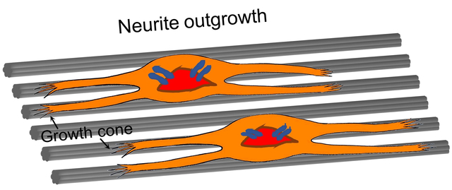
One plus one is always greater than one: The surface of uniaxially aligned microfibers are engraved with nanoscale grooves to augment the outgrowth of neurites and migration of Schwann cells for potential application in nerve regeneration.
Introduction
The outgrowth of neurites and the migration of glial cells both play important roles in the repair or regeneration of injured nerves. In this regard, topographic guidance, biochemical cue, electrical stimulation, or a combination of them are often taken into consideration when designing a nerve guidance conduit (NGC).[1–4] In particular, the surface topography of a substrate has received ever increasing attention as it influences cell behaviors through a direct contact and can be easily integrated with additional biochemical and/or electrical cues. Many studies have been carried out to investigate the relationship between the outgrowth of neurites and various topographic features, including, for example, the alignment and density of electrospun fibers,[5,6] microscale roughness or density gradation provided by electrosprayed microparticles,[7,8] arrays of micro- or nano-pillars formed by photolithography or templating with a porous membrane,[9,10] submicrometer roughness generated by laser-scribed reduction of graphene oxide,[11] and grooved patterns.[12–14] Among the different topographic features, arrays of bulges or pillars and grooved patterns at the nanoscale are considered the most effective in promoting axonal guidance and elongation because they can provide more sensing targets and appropriate contact areas for the growth cones of neurites.[15–17] It is documented that the outgrowth of neurites can be regulated at both subcellular and cellular levels by acting on the growth cones and axons, respectively.[18] As such, the substrate most effective in promoting neurite outgrowth should contain topographic features with two different sizes, about 1 μm and 200 nm, to match the dimensions of typical axons and the filopodia of growth cones.[18] For the same reason, it is expected that microfibers engraved with longitudinal nanoscale grooves should outperform nanofibers in promoting neurite outgrowth.
Electrospun fibers with grooves on the surface have been developed to control the behaviors of glial cells and/or the outgrowth of neurites.[19–21] Owing to the versatility of electrospinning technology, one can simply vary the composition, alignment, diameter, and secondary features by tuning the electrospinning parameters. The methods commonly employed for generating grooves on electrospun fibers involved the use of a specific mixture of solvents,[22–24] laser ablation,[25] stamping,[2] or a specially designed mold as the collector.[19] These methods either need a lot of trials to determine the appropriate types and ratios of the solvents or fail to push the grooves down to the nanoscale. There is still a pressing need to develop a simple method capable of generating nanoscale grooves with the proper dimensions to maximize the alignment and extension of neurites. It will be even more significant if the dimensions of the grooves (i.e., the width of the grooves and the separation between them) can be tightly controlled during the fabrication process.
Various types of surface structures have been observed when fibers are electrospun from a mixture of two immiscible polymers in a common solvent.[26] Based on this strategy, here we report a facile method for fabricating uniaxially aligned microfibers engraved with nanoscale structures (i.e., grooves and/or pores) of controllable dimensions through the use of coaxial electrospinning. We start with uniaxially aligned microfibers as the substrate to generate additional secondary structures because they not only provide a similar orientation to the native nerve fascicles but also match the lateral dimensions of axons (typically, at a micrometer scale). The secondary structures can be engineered at the nanoscale to further guide and enhance the outgrowth of neurites by providing more topographic contacts with the growth cones. Since the neuron niches in vivo are composed of numerous hierarchical structures at micro- and nanoscale, we hypothesize that the shapes and dimensions of the secondary structures will play an important role in augmenting the outgrowth of neurites while controlling the behaviors of glial cells.[18] Taken together, we focus on uniaxially aligned microfibers decorated with different secondary structures (i.e., grooves and pores) while taking different dimensions (i.e., width, thickness, or diameter). We further optimize these hierarchical structures using in vitro models based on PC12 cells and chick embryonic dorsal root ganglia (DRG) bodies for neurite outgrowth, as well as the linear migration of Schwann cells.
Results and Discussion
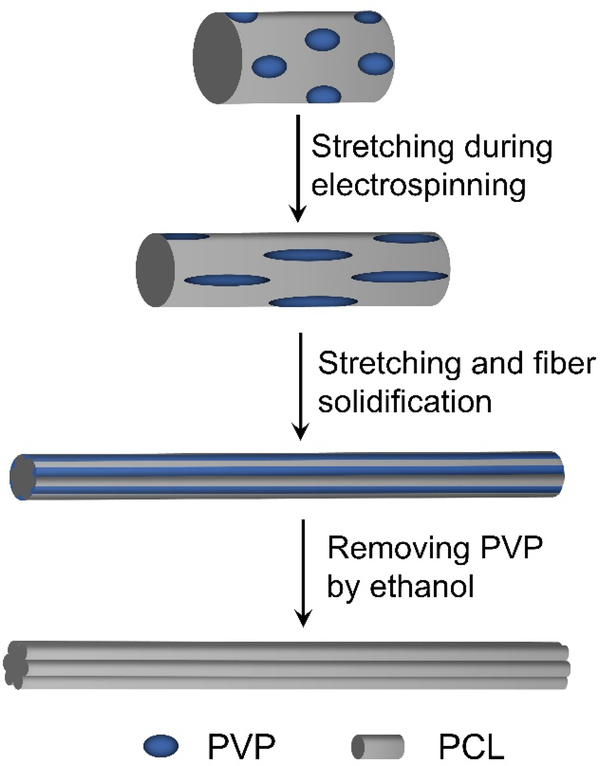
We first confirmed that poly(ε-caprolactone) (PCL) and poly(vinylpyrrolidone) (PVP) were immiscible in 2, 2, 2-trifluoroethanol (TFE). When PCL and PVP were mixed at a mass ratio of 1:1 in TFE, we obtained a homogeneous but turbid emulsion after high-speed stirring overnight (Figure S1). If we stopped stirring and waited for one day, phase separation would occur. The phase separation was also supported by the optical micrographs recorded from the as-obtained emulsion and a film prepared from it. As shown in Figure S2A, the PVP were uniformly dispersed in the PCL solution as PVP/TFE droplets. Upon removing the solvent, the PVP/TFE droplets became individual pockets embedded in a PCL matrix (Figure S2B). By leveraging this phenomenon, we fabricated uniaxially aligned PCL microfibers with their surface engraved with longitudinal grooves. In a typical process, a PCL solution in TFE serves as the inner fluid while the mixture of PCL and PVP (at a mass ratio of 1:2, 1:1, and 2:1, respectively) in TFE is supplied as the outer fluid for coaxial electrospinning. As illustrated in Scheme 1A, phase separation will occur in the outer fluid during the jetting process, leading to the formation of PVP/TFE pockets inside the PCL matrix. The PVP/TFE pockets are then stretched and elongated together with the PCL matrix for their evolution into nanoscale rods in the surface layer on the microfibers. After solidification and then removal of the PVP, we obtained multiple nanoscale grooves on the surface of each microfiber. Nanoscale pores or a mix of grooves and pores can also be generated by varying the content of PVP relative to that of PCL.
Scheme 1.
Schematic illustration showing the formation of nanoscale grooves on the surface of a microfiber during an electrospinning process.
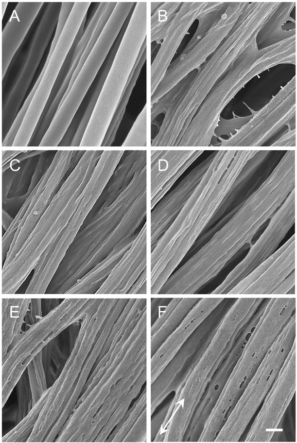
Figure S3 shows SEM images of the uniaxially aligned microfibers electrospun from mixtures of PCL and PVP at different mass ratios and/or at different flow rates (1.0 or 1.5 mL/h) for the outer fluid. Prior to removing PVP, all the microfibers showed a smooth surface. As a reference, we also fabricated PCL microfibers featuring a smooth surface by electrospinning a solution of 20% PCL in a mixture of dichloromethane and N,N-dimethylformamide at a flow rate of 1.0 mL/h, a high voltage of 15 kV, and a collecting distance of 20 cm (Figure 1A). The average diameter of the different types of microfibers was in the range of 1–1.5 μm. By varying the PVP to PCL mass ratio and the flow rate of the outer fluid, we were able to control the type of nanostructures (i.e., grooves versus pores) being formed and their dimensions after washing the microfibers three times with ethanol and deionized water, respectively. As shown in Figure 1, when the mass ratio of PCL to PVP was 1:2 or 1:1, nanoscale grooves were observed on the PCL microfibers, regardless of the flow rate of the outer fluid (Figure 1, B–E). In contrast, nanoscale pores were formed on the PCL microfibers when the mass ratio was changed to 2:1, mainly due to the inadequate amount of PVP in each pocket (Figure 1F). Figure S4 shows magnified SEM images of individual microfibers to reveal the secondary structures on their surfaces. Figure S5 shows a summary of the dimensions of the grooves or pores produced on the microfibers. For the microfibers fabricated at a PCL to PVP mass ratio of 1:2, together with a flow rate of 1.0 mL/h, the width of the grooves and the thickness of the ridges (i.e., the distance between the adjacent grooves) were 254±58 and 381±33 nm, respectively (see Figure 1B). When the flow rate was increased to 1.5 mL/h, these values became 292±42 and 377±52 nm, respectively (see Figure 1C). The increase in flow rate for the outer fluid made the grooves wider. When the PCL to PVP mass ratio was changed to 1:1, these values became 239±54 and 301±56 nm, respectively, for the sample obtained with a flow rate of 1.0 mL/h (see Figure 1D) and 265±44 and 341±36 nm, respectively, for the sample involving the use of a flow rate at 1.5 mL/h (see Figure 1E). When the mass ratio of PCL to PVP was further increased to 2:1, nanoscale pores with a diameter of 118±35 nm were generated on the microfibers (see Figure 1F). We define the PCL microfibers with nanoscale grooves or pores of different dimensions, shown in Figure 1, B–F, as Groups B to F, whereas the PCL microfibers covered by a smooth surface are denoted Group A (Figure 1A).
Figure 1.
SEM images of uniaxially aligned PCL microfibers (A) covered by a smooth surface, and decorated with nanoscale (B−E) grooves and (F) pores, respectively. The grooves or pores were formed by removing PVP from the microfibers fabricated by coaxial electrospinning with PCL/TFE as the inner fluid while the outer fluid contained a mixture of PCL and PVP at mass ratios of (B and C) 1:2, (D and E) 1:1, and (F) 2:1, respectively. During electrospinning, the flow rate of inner fluid was fixed as 1.0 mL/h while that of outer fluid was (B and D) 1.0 or (C, E, and F) 1.5 mL/h. The white arrow indicates the direction of fiber alignment. Scale bar = 1 μm and it applies to all images.
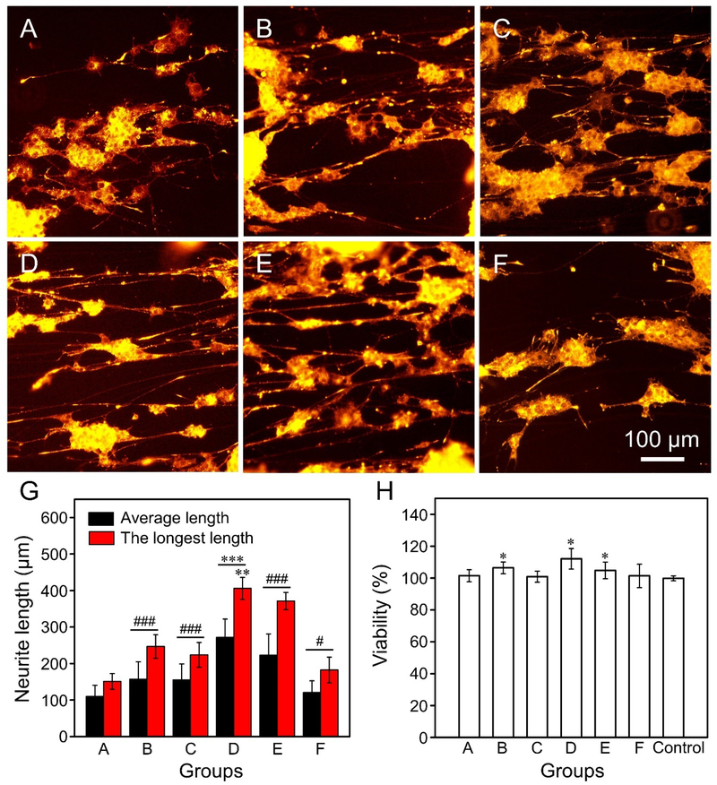
We firstly investigated the influence of the nanoscale grooves and/or pores on the outgrowth of neurites from PC12 cells. In this case, all the samples were coated with a layer of laminin to facilitate the adhesion of PC12 cells. The coating of laminin did not affect the nanostructures on the microfibers (Figure S6). The fluorescence micrographs in Figure 2, A–F, show the neurites extending from PC12 cells after culturing on the different types of uniaxially aligned PCL microfibers for six days. The average and the longest lengths of neurites extending from the PC12 cells in Group D were 271±51 and 406±30 μm, respectively (Figure 2G). These values were significantly greater (P < 0.001) than all other groups for the average length or all the other groups except for Group E (at P < 0.01 level) for the longest length. Compared with the numbers for the PCL microfibers covered by a smooth surface (110±30 and 151±21 μm, respectively), Groups B, C, E, and F showed significantly better performance (P < 0.001 for Groups B, C, and E; P < 0.05 for Group F). The PC12 cells also showed good variability after culturing on the different PCL microfibers for three days (Figure 2H), mainly due to the biocompatibility of PCL and the coating of laminin prior to cell culture.
Figure 2.
(A−F) Fluorescence micrographs showing the neurite extending from PC12 cells after culture on the uniaxially aligned PCL microfibers (A) covered by a smooth surface, and decorated with nanoscale (B−E) grooves and (F) pores, respectively. Note that the microfibers used in Groups A to F corresponded to the same batches shown in Figure 1. (G) The average and longest lengths of neurites extending from the PC12 cells after culturing on the different types of microfibers. ***P < 0.001 as compared with that of cells cultured on all the other groups for the average length or that of cells cultured on all the other groups except Group E (**P < 0.01) for the longest length. ###P < 0.001 and #P < 0.05 as compared with that of cells cultured on PCL microfibers covered by a smooth surface. (H) Viability of PC12 cells after culturing on the different types of microfibers for three days. *P < 0.05 as compared with that of cells cultured on the control group (glass slides).
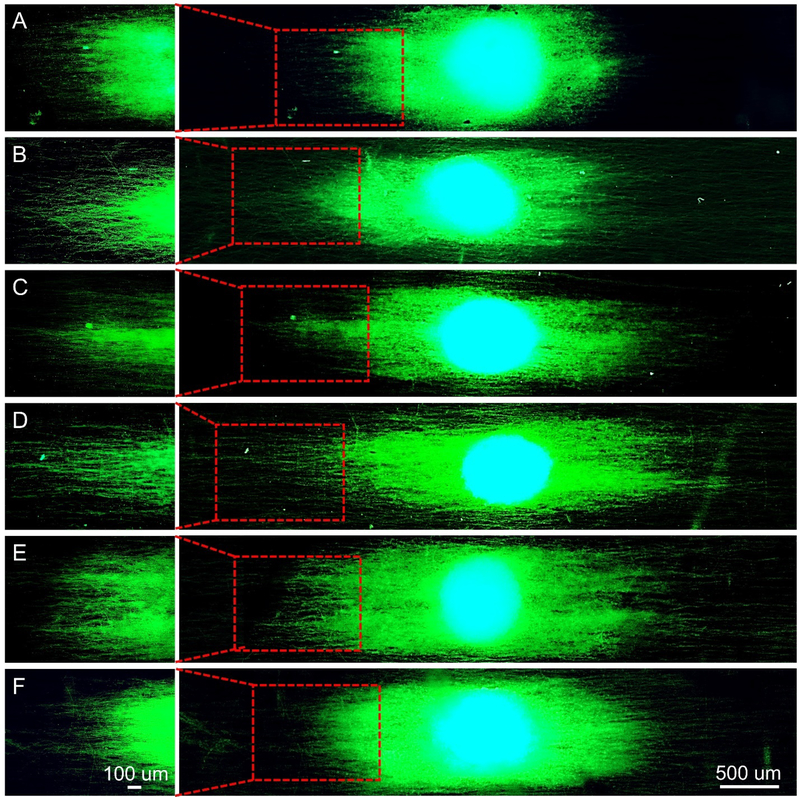
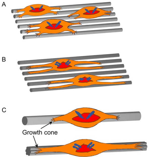
For the neurite outgrowth from DRG bodies, we obtained a similar trend for the different types of PCL microfibers. As shown in Figure 3, A–F, the neurites were extended from DRG bodies along the uniaxial alignment of the underneath microfibers, regardless of the secondary structures in the different groups. It has been reported that the microscale topographies (e.g., micro-channels or micro-pillar arrays) with feature sizes larger than 1 μm could have impacts on neuronal outgrowth at the cellular scale.[27] In our previous study, we also found that the orientation of the underlying fibers significantly influenced the outcome of neurite extension.[28] For example, the neurites extending from DRG bodies on uniaxially aligned microfibers were significantly longer than those cultured on a tissue culture plate. Here we aim to further enhance the impact of topographic guidance on neurite outgrowth by decorating the microfibers with nanoscale secondary structures, such as grooves or pores, to act on filopodia by exerting localized influences at the subcellular scale.[27] Scheme 2 shows a comparison of neurite extension when the neurons are cultured on the PCL microfibers with different surface structures. Due to the alignment of the nanoscale grooves, the neurites are able to extend to a longer pathway on the groove-engraved fibers relative to the microfibers covered by a smooth surface.
Figure 3.
Fluorescence micrographs showing typical neurite fields extending from DRG bodies when cultured on the uniaxially aligned PCL microfibers (A) covered by a smooth surface, and decorated with nanoscale (B−E) grooves and (F) pores, respectively. The neurites were stained with Tuj1 primary antibody (green) and cell nuclei were stained with 4′,6 diamidino-2-phenylindole (blue). Note that the microfibers used in Groups A to F corresponded to the same batches shown in Figure 1.
Scheme 2.
Schematic illustration showing the outgrowth of neurites from the DRG bodies cultured (A, B) on the scaffolds comprised of uniaxially aligned microfibers (A) with a smooth surface versus (B) decorated with nanoscale grooves, and (C) on one individual microfiber accordingly at a magnified view.
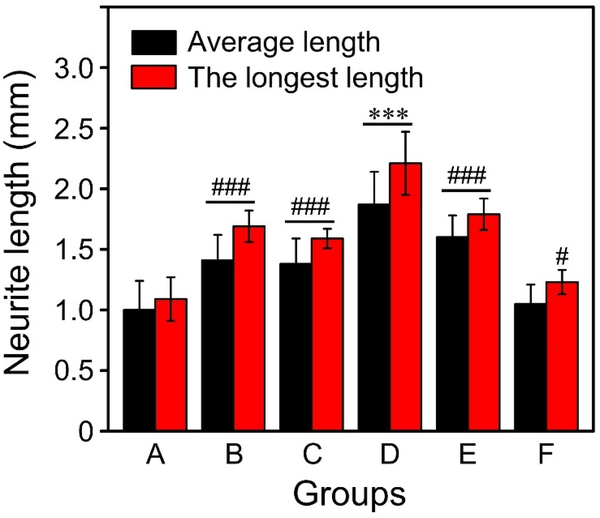
As shown in Figure 4, the neurites extending from DRG bodies took a significantly longer path (P < 0.001) on the microfibers featuring nanoscale grooves (Groups B, C, D, and E) relative to the microfibers covered by a smooth surface. In contrast, the microfibers decorated with nanoscale pores (Group F) showed no significant difference for the average neurite length or only had a significant difference at P < 0.05 level for the longest neurite length in reference to the microfibers featuring a smooth surface. Significantly, the average and longest lengths of the neurites involving the use of PCL microfibers engraved with grooves in Group D reached 1.9±0.3 and 2.2±0.3 mm, respectively. These values are significantly greater (P < 0.001) than all other groups, in particular, almost doubled relative to the microfibers covered by a smooth surface in terms of average length (1.0±0.2 mm) and the longest length (1.1±0.2 mm). We also found that both the shortest and median lengths of neurites extending from the DRG bodies were significantly increased (P < 0.01 for the shortest length; P < 0.001 for the median length) when the PCL microfibers featuring a smooth surface were replaced by groove-engraved microfibers in Groups D and E (Figure S7). For the microfibers in Groups B, C, and F, however, they only showed significant difference for the median length (P < 0.01 for Groups B and C; P < 0.05 for Group F). These results confirmed that Group D contained microfibers with grooves (239±54 nm in width) best-suited for guiding the extension of filopodia (200 nm in size).[18] Their thinner ridges relative to the fibers in Groups B, C, and E also led to the formation of grooves at a higher density, further contributing to the best performance in terms of neurite extension from both PC12 cells and DRG bodies.
Figure 4.
The average and longest lengths of neurites extending from DRG bodies after culturing on the different types of microfibers for six days. The Groups A to F corresponded to those in Figure 3. ***P < 0.001 as compared with all other groups. ###P < 0.001 and #P < 0.05 as compared with the PCL microfibers covered by a smooth surface (Group A).
A similar trend has also been observed in a study involving polyurethane acrylate substrates patterned with nanoscale grooves through UV-assisted capillary force lithography.[29] It was shown that the nanostructures with a smaller dimension (e.g., grooves with width at 300 nm versus 600, 900, 1200, and 1500 nm) were found to be more effective in enhancing focal adhesion of neural stem cells for their differentiation toward neurons. Although these flat and often rigid substrates are convenient for in vitro studies, they cannot be adapted for the fabrication of NGCs.[29–31] In this regard, electrospun fibers offer an immediate advantage because the mat of fibers can be easily rolled up to obtain NGCs with tunable diameters to match the sizes of various types of nerves. Besides, the groove-engraved microfibers developed in this work can be made with controlled biodegradability by varying the formulation of the core solution. The fibers can also serve as carriers for the encapsulation and controlled release of proteins and/or growth factors.
In addition to the outgrowth of neurites, the migration of glial cells also plays an important role during nerve regeneration.[32–35] As such, a conduit consisting of both micro and nanoscale features should work the best in promoting both neurite extension and glial cell migration during nerve repair. To this end, we investigated the migration of Schwann cells on the different types of PCL microfibers. With the use of polydimethylsiloxane blocks, we seeded the cells on the left side of the mat (a region with a width of 0.5 mm) consisting of the PCL microfibers with different surface structures. After cell adhesion, the polydimethylsiloxane blocks were removed, allowing the cells to migrate toward the right side. As shown by the fluorescence micrographs in Figure S8, the cells migrated along the uniaxial alignment owing to the contact guidance arising from the underneath microfibers. The yellow color displayed by the cells can be attributed to the overlap of F-actin (red) and vinculin (green) staining, indicating the cells had cytoskeletal expression and focal adhesion, respectively.
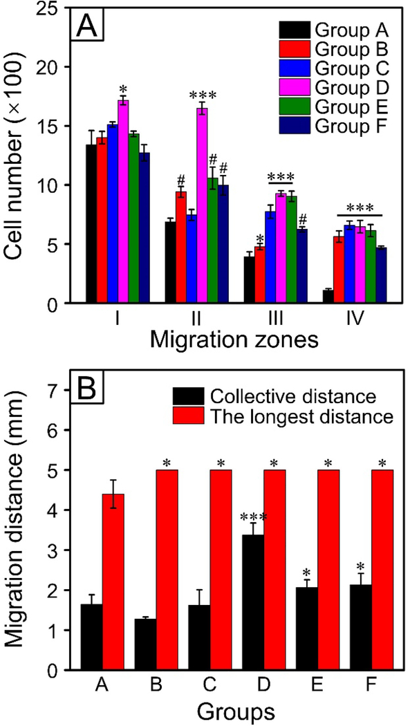
We then investigated the migration of Schwann cells by measuring the migrated cell numbers. The migration gap was separated into four regions, as illustrated in Figure S8. In regions III and IV, the numbers of migrated cells for the microfibers engraved with nanoscale grooves were all greater relative to the case of microfibers covered by a smooth surface (Figure 5A). In particular, the microfibers in Group D showed much more migrated cells (at P < 0.05 level for region I; at P < 0.001 level for regions II, III, and IV) relative to the microfibers with a smooth surface, indicating the best performance regarding Schwann cell migration. We also observed that the cell numbers tended to vary in the different migration regions of the same sample. Since the cells were seeded in a specific region (termed “seeding zone”) on the left side of each mat, they would take different pathways to migrate from regions I to IV. For the migration of collective cells, however, the drive force was mainly provided by the movement of leader cells and the interaction between follower and leader cells.[36] Because of the intraindividual and interindividual variations in cell motility, we expect to have different geometries for the cell cluster or cell monolayer and thus diversity in terms of cell-cell collision and adhesion.[37] Besides, the number of adjacent empty locations in the neighborhood also affected the activity of cell migration. Taken together, the cell population cannot keep marching as one unit, giving rise to dissimilar cell numbers in the different migration regions.
Figure 5.
(A) The number of Schwann cells in the different migration zones and (B) the migration distance of Schwann cells on the different samples. Groups A to F corresponded to those shown in Figure S8. ***P < 0.001, #P < 0.01, and *P < 0.05 as compared with that of cells cultured on the PCL microfibers covered by a smooth surface (Group A).
We also measured the migrated distances of cells for the microfibers with different surface structures. As shown in Figure 5B, the microfibers in Group D showed the best performance with regard to the collective migration of cells, with a P < 0.001 significant difference with reference to the microfibers covered by a smooth surface. The longest migration distances for cells on the microfibers engraved with nanoscale grooves and pores (Groups B to F) were all significantly greater (at P < 0.05 level) relative to the microfibers covered by a smooth surface (Group A). For the shortest migration distance, however, only the microfibers in Group D showed significant difference (at P < 0.001 level) when compared with that of cells cultured on the microfibers covered by a smooth surface (Figure S9). Among others, the microfibers in Groups C, D, and E showed significant difference (P < 0.05 for Group C; P < 0.01 for Groups D and E) for the median migration distance with reference to the case involving the use of microfibers featuring a smooth surface. As shown in Figure S10, Schwann cells showed good viability on all types of PCL microfibers relative to the control group (glass slides). We found that the cells migrated on the microfibers in Groups D and E tended to stretch and spread, while some of the cells in Groups B, C, and F aggregated together along with the migration (Figure S8 and S11). The thinnest ridges for the microfibers in Group D gave the cells the highest possibility to sense the grooves and migrate along the alignment. Although the sensing targets provided by the nanoscale pores on the microfibers also have positive impact on directing the extension of neurites and linear migration of Schwann cells, they should be less effective than grooves because of the discontinuity of pores along the axis of a fiber.
It has been documented that the grooved structures can positively affect the alignment and differentiation of various types of neurocytes, including neural stem cells[29,38] and primary hippocampal neurons,[11] and the cells are often arranged with a better orientation in thinner grooves. A grooved pattern covered by a monolayer of astrocytes have also been used to keep the orientation of neuronal cells and support myelination at the same time.[39] In this regard, the groove-engraved microfibers can be extended to work with various types of cells, for example, stem cells (e.g., neural stem cells, adipose-derived stem cells, and pluripotent stem cells) for their focal adhesion and neuronal differentiation. The NGCs made of such microfibers, together with the use of other types of signals (e.g., biochemical cues and electrical stimulations), are also expected to provide a synergistic effect on axon regrowth for the repair of injured nerves.
Conclusion
In summary, we have demonstrated that PCL microfibers engraved with nanoscale grooves and/or pores can be fabricated using coaxial electrospinning by leveraging the immiscibility between PCL and PVP in TFE. By varying the PCL to PVP mass ratio and the flow rates for inner and outer fluids, the dimensions of the grooves can be optimized to maximize the guidance for the extension of neurites and migration of glial cells. For the aligned microfibers engraved with grooves of 239±54 nm in width, together with a thickness of 301±56 nm for the ridges, we obtained the best performance in terms of neurite extension and Schwann cell migration. Such aligned microfibers can be directly used to construct NGCs and further integrated with gradients in terms of proteins and/or growth factors[40,41] to augment the efficacy of nerve repair.
Supplementary Material
Acknowledgements
This work was supported in part by a grant from the National Institutes of Health (R01 EB020050) and startup funds from the Georgia Institute of Technology. The characterization work was also performed in part at the Georgia Tech Institute for Electronics and Nanotechnology, a member of the National Nanotechnology Coordinated Infrastructure (NNCI), which is supported by the National Science Foundation (ECCS-1542174).
Footnotes
Conflict of Interest
The authors declare no conflict of interest.
Supporting Information
Supporting Information is available from the Wiley Online Library or from the author.
Contributor Information
Tong Wu, The Wallace H. Coulter Department of Biomedical Engineering, Georgia Institute of Technology and Emory University, Atlanta, GA 30332, USA.
Jiajia Xue, The Wallace H. Coulter Department of Biomedical Engineering, Georgia Institute of Technology and Emory University, Atlanta, GA 30332, USA.
Younan Xia, The Wallace H. Coulter Department of Biomedical Engineering, Georgia Institute of Technology and Emory University, Atlanta, GA 30332, USA; School of Chemistry and Biochemistry, School of Chemical and Biomolecular Engineering, Georgia Institute of Technology, Atlanta, GA 30332, USA.
References
- [1].Tonazzini I, Jacchetti E, Meucci S, Beltram F, Cecchini M, Adv. Healthcare Mater. 2015, 4, 1849. [DOI] [PubMed] [Google Scholar]
- [2].Zhang D, Wu S, Feng J, Duan Y, Xing D, Gao C, Acta Biomater. 2018, 74, 143. [DOI] [PubMed] [Google Scholar]
- [3].Sun B, Wu T, Wang J, Li D, Wang J, Gao Q, Bhutto MA, El-Hamshary H, Al-Deyab SS, Mo X, J. Mater. Chem. B 2016, 4, 6670. [DOI] [PubMed] [Google Scholar]
- [4].Abidian MR, Corey JM, Kipke DR, Martin DC, Small 2010, 6, 421. [DOI] [PMC free article] [PubMed] [Google Scholar]
- [5].Xie J, MacEwan MR, Li X, Sakiyama-Elbert SE, Xia Y, ACS Nano 2009, 3, 1151. [DOI] [PMC free article] [PubMed] [Google Scholar]
- [6].Xie J, Liu W, MacEwan MR, Bridgman PC, Xia Y, ACS Nano 2014, 8, 1878. [DOI] [PMC free article] [PubMed] [Google Scholar]
- [7].Xue J, Wu T, Li J, Zhu C, Xia Y, Angew. Chem., Int. Ed. 2019, 58, 3948. [DOI] [PMC free article] [PubMed] [Google Scholar]
- [8].Li X, Macewan MR, Xie J, Siewe D, Yuan X, Xia Y, Adv. Funct. Mater. 2010, 20, 1632. [DOI] [PMC free article] [PubMed] [Google Scholar]
- [9].Leclech C, Renner M, Villard C, Metin C, Biomaterials 2019, 214, 119194. [DOI] [PubMed] [Google Scholar]
- [10].Seo J, Kim J, Joo S, Choi JY, Kang K, Cho WK, Choi IS, Small 2018, 14, 1801763. [DOI] [PubMed] [Google Scholar]
- [11].Lee SH, Lee HB, Kim Y, Jeong JR, Lee MH, Kang K, Nano Lett. 2018, 18, 7421. [DOI] [PubMed] [Google Scholar]
- [12].Kang E, Choi YY, Chae SK, Moon JH, Chang JY, Lee SH, Adv. Mater. 2012, 24, 4271. [DOI] [PubMed] [Google Scholar]
- [13].Koppes RA, Park S, Hood T, Jia X, Abdolrahim Poorheravi N, Achyuta AH, Fink Y, Anikeeva P, Biomaterials 2016, 81, 27. [DOI] [PMC free article] [PubMed] [Google Scholar]
- [14].Chen Y, Taskin MB, Zhang Z, Su Y, Han X, Chen M, Biomater. Sci. 2019, 7, 2165. [DOI] [PubMed] [Google Scholar]
- [15].He J, Sun C, Gu Z, Yang Y, Gu M, Xue C, Xie Z, Ren H, Wang Y, Liu Y, Liu M, Ding F, Leong KW, Gu X, ACS Nano 2018, 12, 9660. [DOI] [PubMed] [Google Scholar]
- [16].Viktorija R, Ana B, Petar D, Dries B, Damir K, J. Neural Eng 2019, 16, 066037.31189144 [Google Scholar]
- [17].Mattila PK, Lappalainen P, Nat. Rev. Mol. Cell Biol. 2008, 9, 446. [DOI] [PubMed] [Google Scholar]
- [18].Kang K, Yoon SY, Choi SE, Kim MH, Park M, Nam Y, Lee JS, Choi IS, Angew. Chem., Int. Ed. 2014, 53, 6075. [DOI] [PubMed] [Google Scholar]
- [19].Zhang L, Chen S, Liang R, Chen Y, Li S, Li S, Sun Z, Wang Y, Li G, Ming A, Yang Y, J. Biomed. Mater. Res., Part A 2018, 106, 3123. [DOI] [PubMed] [Google Scholar]
- [20].Huang C, Ouyang Y, Niu H, He N, Ke Q, Jin X, Li D, Fang J, Liu W, Fan C, Lin T, ACS Appl. Mater. Interfaces 2015, 7, 7189. [DOI] [PubMed] [Google Scholar]
- [21].Simitzi C, Ranella A, Stratakis E, Acta Biomater. 2017, 51, 21. [DOI] [PubMed] [Google Scholar]
- [22].Omidinia-Anarkoli A, Rimal R, Chandorkar Y, Gehlen DB, Rose JC, Rahimi K, Haraszti T, De Laporte L, ACS Appl. Mater. Interfaces 2019, 11, 7671. [DOI] [PubMed] [Google Scholar]
- [23].Huang C, Tang Y, Liu X, Sutti A, Ke Q, Mo X, Wang X, Morsi Y, Lin T, Soft Matter 2011, 7, 10812. [Google Scholar]
- [24].Liu W, Huang C, Jin X, Nanoscale Res. Lett. 2015, 10, 237. [DOI] [PMC free article] [PubMed] [Google Scholar]
- [25].Jun I, Chung YW, Heo YH, Han HS, Park J, Jeong H, Lee H, Lee YB, Kim YC, Seok HK, Shin H, Jeon H, ACS Appl. Mater. Interfaces 2016, 8, 3407. [DOI] [PubMed] [Google Scholar]
- [26].Greiner A, Wendorff JH, Angew. Chem., Int. Ed. 2007, 46, 5670. [DOI] [PubMed] [Google Scholar]
- [27].Kang K, Choi SE, Jang HS, Cho WK, Nam Y, Choi IS, Lee JS, Angew. Chem., Int. Ed. 2012, 51, 2855. [DOI] [PubMed] [Google Scholar]
- [28].Xue J, Yang J, O’Connor DM, Zhu C, Huo D, Boulis NM, Xia Y, ACS Appl. Mater. Interfaces 2017, 9, 12299. [DOI] [PMC free article] [PubMed] [Google Scholar]
- [29].Yang K, Jung K, Ko E, Kim J, Park KI, Kim J, Cho SW, ACS Appl. Mater. Interfaces 2013, 5, 10529. [DOI] [PubMed] [Google Scholar]
- [30].Chen CH, Tsai CC, Wu PT, Wang IK, Yu J, Tsai WB, ACS Appl. Bio Mater. 2018, 2, 205. [DOI] [PubMed] [Google Scholar]
- [31].Yang K, Yu SJ, Lee JS, Lee HR, Chang GE, Seo J, Lee T, Cheong E, Im SG, Cho SW, Nanoscale 2017, 9, 18737. [DOI] [PubMed] [Google Scholar]
- [32].Motta CMM, Endres KJ, Wesdemiotis C, Willits RK, Becker ML, Biomaterials 2019, 218, 119335. [DOI] [PMC free article] [PubMed] [Google Scholar]
- [33].Simitzi C, Efstathopoulos P, Kourgiantaki A, Ranella A, Charalampopoulos I, Fotakis C, Athanassakis I, Stratakis E, Gravanis A, Biomaterials 2015, 67, 115. [DOI] [PubMed] [Google Scholar]
- [34].Masciullo C, Dell’Anna R, Tonazzini I, Boettger R, Pepponi G, Cecchini M, Nanoscale 2017, 9, 14861. [DOI] [PubMed] [Google Scholar]
- [35].Patel BB, Sharifi F, Stroud DP, Montazami R, Hashemi NN, Sakaguchi DS, Macromol. Biosci. 2019, 19, 1800236. [DOI] [PubMed] [Google Scholar]
- [36].Mayor R, Etienne-Manneville S, Nat. Rev. Mol. Cell Biol. 2016, 17, 97. [DOI] [PubMed] [Google Scholar]
- [37].Rosello C, Ballet P, Planus E, Tracqui P, Acta Biotheor. 2004, 52, 343. [DOI] [PubMed] [Google Scholar]
- [38].Béduer A, Vieu C, Arnauduc F, Sol JC, Loubinoux I, Vaysse L, Biomaterials 2012, 33, 504. [DOI] [PubMed] [Google Scholar]
- [39].Sørensen A, Alekseeva T, Katechia K, Robertson M, Riehle MO, Barnett SC, Biomaterials 2007, 28, 5498. [DOI] [PubMed] [Google Scholar]
- [40].Wu T, Xue J, Li H, Zhu C, Mo X, Xia Y, ACS Appl. Mater. Interfaces 2018, 10, 8536. [DOI] [PMC free article] [PubMed] [Google Scholar]
- [41].Tanes ML, Xue J, Xia Y, J. Mater. Chem. B 2017, 5, 5580. [DOI] [PMC free article] [PubMed] [Google Scholar]
Associated Data
This section collects any data citations, data availability statements, or supplementary materials included in this article.


