

Abstract
Cardiovascular diseases (CVDs) are one of the leading causes of mortality worldwide and a number one killer in the USA. Cell-based approaches to treat CVDs have only shown modest improvement due to poor survival, retention, and engraftment of the transplanted cells in the ischemic myocardium. Recently, tissue engineering and the use of 3D scaffolds for culturing and delivering stem cells for ischemic heart disease are gaining rapid potential. Here, we describe a protocol for the fabrication of aligned coaxial nanofibrous scaffold comprising of a polycaprolactone (PCL) core and gelatin shell. Furthermore, we describe a detailed protocol for the efficient seeding and maintenance of human-induced pluripotent stem cell-derived cardiomyocytes (hiPSC-CMs) on these nanofibrous scaffolds, which could have a potential application in the generation of functional “cardiac patch” for myocardial repair applications as well as an in vitro 3D cardiac tissue model to evaluate the efficacy of cardiovascular drugs and cardiac toxicities.
Keywords: Electrospinning, Nanofibrous scaffolds, Cardiomyocytes, Cardiac repair
1. Introduction
Cell-based approaches have become an integral part in the field of regenerative medicine, especially for organs with limited or no regenerative potential, for example, the heart. Although a number of different cell types, including various stem/progenitor cells as well as cardiomyocytes, have been studied, only a modest improvement in cardiac function has been reported following transplantation into the ischemic myocardium. A vast majority of the studies have attributed this to poor retention and low survival ofthe cells at the site of infarction [1]. To overcome these limitations, tissue-engineering techniques have been employed in combination with cells to improve the ease of cell delivery as well as retention [2]. Among these techniques, use of 3D bioengineered scaffolds in combination with different cell types has become increasingly popular. Such scaffolds have been successfully used in various preclinical [3] as well as clinical studies [4]. However, several factors have been shown to influence the successful use of such bioengineered scaffolds for cardiac applications, namely, the nature of biomaterial used, mechanical properties of the scaffolds, thickness and dimensions, and alignment [2, 5].
Studies have reported the use of natural biomaterials such as collagen, gelatin, and fibrin in scaffolds for culturing cardiomyocytes [6]. While these materials do not alter cell viability or function, they have been shown to exhibit poor strength and stiffness [7]. On the other hand, synthetic polymers like polycaprolactone (PCL) and poly (lactic-co-glycolic acid) (PLGA) have been used to fabricate scaffolds with better mechanical properties, but the adhesion and survival of cells on these patches were low [8, 9]. Coaxial (CoA) nanofiber systems, with a synthetic polymer (PCL or PLA) in the core and a more adhesive natural material (gelatin) as the shell, exhibited both mechanical strength, high cell adhesion and viability, and lower in vitro production of inflammatory cytokines when compared to purely synthetic nanofibrous scaffold [8, 10]. For tissue-engineering applications, among various available techniques, electrospinning has been extensively used for fabricating nanofibrous scaffolds [2]. In this chapter, we present a method for the fabrication of an aligned polycaprolactone (PCL)–gelatin co-axial nanofibrous scaffold for the development of cardiac patch, which could be implanted along with hiPSC-CMs on the epicardial heart surface for potential cardiac tissue regeneration.
2. Materials
Prepare all reagents using sterile ultrapure water and culture-grade reagents. Prepare and store all reagents at room temperature (until mentioned otherwise). Prepare all organic solvents in a chemical hood and use the appropriate personal protective equipment.
2.1. Electrospinning
12 wt./vol.% Gelatin solution: Dissolve 1.2 g of gelatin from bovine skin in 10 ml of 1,1,1,3,3,3-hexafluoro-2-propanol (HFIP) (see Note 1).
8 wt./vol.% Polycaprolactone (PCL): Dissolve 0.4 g of PCL in 5 ml of 1,1,1,3,3,3-hexafluoro-2-propanol (HFIP) (see Note 1).
18-gage needle.
T-shaped spinneret tube.
Syringe pumps.
Rotating collector.
2.2. Cross-Linking
7 mM N-(3-Dimethylaminopropyl)-N′ ethylcarbodiimide hydrochloride (EDC) solution (cross-linking solution): Dissolve EDC in sterile 100% ethanol.
Sterile 70% ethanol.
Sterile phosphate-buffered saline (PBS).
Biopsy punch (8 mm).
Sterile forceps.
94-mm dishes.
2.3. Culture of hiPSC-CMs
hiPSC-CMs (Fujifilm Cellular Dynamics, WI): Thaw and culture hiPSC-CMs as per the manufacturer’s instructions on 1% gelatin-coated 6-well plates [11].
50 μg/ml Fibronectin solution: Dissolve 50 μg of human fibronectin in 1 ml of PBS.
iCell cardiomyocyte maintenance medium (CMM, Fujifilm Cellular Dynamics, WI).
0.25% trypsin-EDTA.
94-mm tissue culture-treated dishes.
6-well plates.
Sterile sponge (see Note 2).
Sterile N-Terface (Winfield Labs; see Note 2).
Autoclaved forceps and scissors.
2.4. Scanning Electron Microscopy
4% paraformaldehyde (PFA) solution: Dissolve 4 g of PFA in 100 ml of PBS.
50%, 70%, 80%, 95%, and 100% ethanol gradients (in PBS).
25%, 50%, 75%, and 100% Hexamethyldisilazane (HDMS) gradients (in ethanol).
Carbon tape.
2.5. Confocal Microscopy
Gelatin-fluorescein solution: Dissolve 1 g of fluorescein in 100 ml of 12% gelatin solution.
PCL-rhodamine solution: Dissolve 1 g of rhodamine in 100 ml of 8% PCL solution.
Glass slides.
Coverslips.
Prolong diamond antifade.
3. Methods
3.1. Scaffold Preparation
Setting up a CoA spinneret: Insert an 18-G needle through a T-shaped spinneret tube to obtain a CoA spinneret setup. Manually wrap the 18-G needle with a thin wire to ensure that the inner needle is positioned at the center of the T-shaped spinneret and does not move vertically or laterally (see Notes 3 and 4). Figure 1 shows the schematic of the entire electrospinning setup (see Note 5).
Set up the syringe pumps to feed 12 wt./vol.% gelatin solution and 8 wt./vol.% PCL solution at flow rates of 4 ml/h and 1 ml/h, respectively (see Note 6).
Adjust the distance between the spinneret nozzle and the grounded rotating collector to 20 cm (see Note 7).
Maintain the co-axial spinneret nozzle at a voltage of 20 kV.
Collect the aligned co-axial nanofibers which start forming on the rotating collector, when the voltage is applied on the nozzle and the collector grounded.
Allow the collected aligned co-axial nanofibers to dry overnight in the chemical hood in order to remove the remnant solvent (see Note 8).
Fig. 1.

Electrospinning setup for fabrication of aligned coaxial (CoA) PCL-gelatin nanofibrous scaffold. The 8% PCL solution (red) and 12% gelatin (green) were pumped at 1 ml/h and 4 ml/h, respectively, through the coaxial nozzle such that gelatin flows through the outer nozzle while PCL flows through the inner nozzle. A voltage of 20 kV is applied to the nozzle tip. The extruded nanofibers have an outer shell of gelatin and an inner core made of PCL. The fibers are collected onto a rotating collector to obtain aligned CoA nanofibrous scaffolds
3.1.1. Support Protocol 1: Scanning Electron Microscopy of Scaffolds
The alignment of the nanofibers in the scaffold and the uniformity of the fibers can be analyzed by scanning electron microscopy (SEM, Fig. 2):
Fig. 2.
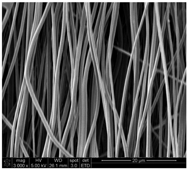
Scanning electron microscopy (SEM) of coaxial aligned nanofibers: SEM image shows aligned (parallel) nanofibers within the scaffold. Scale bar: 20 μm
Cut a 0.5-cm × 0.5-cm piece of the nanofibrous scaffold.
Mount the piece onto a carbon tape and subject it to gold–palladium sputter coating as per the instrument manufacturer’s instructions.
Image the coated scaffolds under a scanning electron microscope.
3.1.2. Support Protocol 2: Confocal Microscopy of Scaffolds
The co-axial nature of the nanofibers formed can be verified by confocal microscopy as previously reported [8]:
Use gelatin and PCL solutions containing fluorescein and rhodamine, respectively, for fabrication of the nanofibers as described above.
Cut small pieces of the nanofiber scaffold and follow the cross-linking process as mentioned in Subheading 3.2.
Place a small piece of the scaffold onto a glass slide.
Mount a glass coverslip on the scaffold with 1–2 drops of Prolong Diamond Antifade.
Image the nanofibers under a confocal microscope (see Note 9).
3.2. Cross-Linking and Sterilization
Using a biopsy punch, cut the aligned CoA nanofibrous scaffold into small circular pieces (Fig. 3).
Place the scaffold in a 94-mm dish containing cross-linking solution overnight at room temperature.
Wash the scaffold in 70% ethanol for 24 h to sterilize the scaffold.
Wash the scaffold thrice in sterile PBS in the biosafety cabinet.
Fig. 3.

Crosslinking, coating, and seeding hiPSC-CMs on the aligned nanofibrous scaffold. (a) The aligned nanofibrous scaffold obtained by electrospinning is cut into an 8-mm scaffold using a biopsy punch and cross-linked using 7 mM EDC solution. The cross-linked scaffold is sterilized by washing with 70% ethanol followed by PBS. (b) For coating, the cross-linked scaffold is placed on the N-Terface and kept in 94-mm dishes containing drops of PBS (to prevent evaporation). Thirty microliters of 50 μg/ml fibronectin is added onto the scaffold and incubated for 1 h at 37 °C. (c) For seeding hiPSC-CMs onto the scaffold, a sterile sponge is placed in a 94-mm dish and sequentially washed with PBS and cardiomyocyte maintenance medium (CMM). The fibronectin-coated scaffold along with the N-Terface is placed on the inoculation sponge, and cell suspension is added dropwise onto the scaffold. The dish is incubated for 2–4 h at 37 °C, 5% CO2. (d) The scaffold along with the N-Terface is placed in a 6-well plate containing CMM and incubated overnight. The following day, the N-Terface is removed and scaffolds are left freely floating in CMM
3.3. Seeding hiPSC-CMs on an Aligned Nanofibrous Scaffold
3.3.1. Coating of Scaffold
Cut out 20-mm × 20-mm squares of the sterile N-Terface and place the pieces carefully in a 94-mm dish (Fig. 3).
Place one cross-linked 8-mm scaffold on the N-Terface care-fully using sterile forceps (see Note 10).
Add 30 μl of fibronectin solution onto each scaffold. Avoid spilling over of the fibronectin out of the scaffold (see Note 11).
Incubate the scaffold at 37 °C for at least 1 h.
3.3.2. Seeding Cells on the Scaffold
Place a sterile sponge in a 94-mm dish and add 15 ml of PBS over it (Fig. 3). Once the sponge is completely soaked in PBS, aspirate out the PBS. Lightly press the sponge to ensure complete removal of PBS. Repeat this step twice.
Repeat step 1 with CMM.
Transfer the scaffold along with the N-Terface onto the sponge as shown in Fig. 3.
Wash the hiPSC-CMs twice with PBS to remove any traces of medium in it.
Add 1 ml of 0.25% trypsin-EDTA (pre-warmed at 37 °C) per well of a 6-well plate.
Incubate the cells at 37 °C for 5–7 min (see Note 12).
Add equal volume of CMM to the cells to neutralize trypsin activity. Dislodge the cells from the cell culture plate by gentle pipetting (see Note 13).
Collect the cells into a 15-ml centrifuge tube. Centrifuge the cells at 300 × g for 10 min at RT.
Re-suspend the cell pellet in 5 ml of CMM and count the number of cells.
Centrifuge the cells again at 300 × g for 10 min at RT and re-suspend the cells in appropriate volume of CMM to obtain 0.5 million cells/50 μl (see Note 14).
Add 25 μl of cell suspension onto each scaffold. After 2–5 min, add 25 μl of cell suspension once again onto each scaffold (see Note 15).
Carefully place the dish in the incubator at 37 °C, 5% CO2 for 4–6 h.
At the end of incubation, carefully pick the N-Terface along with the scaffold using forceps and transfer them into a 6-well plate containing 2 ml of CMM/well (see Note 16).
Incubate the scaffold at 37 °C, 5% CO2 overnight.
The following day, carefully remove the N-Terface from under the scaffold without disturbing the orientation of the scaffold (see Note 17, Fig. 3).
Add an additional 1 ml of CMM per well of the 6-well plate.
Change the medium for the scaffold after every 48 h.
Support Protocol 3: Scanning Electron Microscopy of Cells
The hiPSC-CMs seeded onto the scaffold can be imaged using scanning electron microscopy (SEM, Fig. 4):
Fig. 4.

Scanning electron microscope imaging of hiPSC-CMs cultured on aligned nanofibers: SEM image shows stoichiometric alignment of hiPSC-CMs in the direction of nanofibers within the cardiac scaffold. Scale bar: 50 μm
Wash the hiPSC-CMs cultured on the aligned nanofibrous scaffold with PBS (two times).
Fix the scaffold in 4% PFA for 20 min at RT.
Wash the scaffold twice in PBS.
Gradually dehydrate the scaffold using 50%, 70%, 80%, 95%, and 100% ethanol gradients. Incubate the scaffold for 20 min in each gradient solution.
Gradually dry the scaffold using 25%, 50%, 75%, and 100% HDMS gradients. Incubate the scaffold for 10 min in each solution. After incubation in 100% HDMS for 10 min, remove HDMS and allow it to evaporate completely in the hood before cutting the scaffold.
Make a cut on the scaffold (approximately 75% of the diameter).
Mount the scaffold onto the carbon tape and fold the scaffold along the slit such that both the sides of the scaffold are exposed on the top for sputter coating.
Subject the scaffold to gold-palladium sputter coating as per the instrument manufacturer’s instructions.
Image the coated scaffolds under a scanning electron microscope.
5. Troubleshooting
Low viability of hiPSC-CMs after trypsinization: Loss of cell viability may occur if the cells are over-trypsinized. Neutralize trypsin activity once the cells start to detach from the dish. Minimize the number of times the cells are pipetted to re-suspend the cell pellet.
Poor attachment of hiPSC-CMs onto the scaffold: This may occur in case of improper fibronectin coating. Do not allow the fibronectin drop to dry during coating. Additional drops of PBS may be placed in the dish to maintain humidity in the dish. If the problem persists, increase the concentration of fibronectin used for coating (e.g., 60–70 μg/ml) or leave the scaffolds on the sponge overnight to give more time of attachment. Also, while handling the scaffold, make sure that the tip of the forceps does not scrap off cells attached to the scaffold.
- No contracting (beating) scaffolds: Normally, the contracting scaffolds are observed with 48–72 h of seeding the hiPSC-CMs onto the scaffold. In case no contractility is observed,
- Ensure that the hiPSC-CMs show a synchronous contractility in gelatin-coated dishes before seeding them onto the scaffold. hiPSC-CMs may show some batch-to-batch variation in the initiation of synchronous contractility. However, the time may vary depending on the batch of hiPSC-CMs used.
- If SEM analysis shows absence of cells, the drop of cell suspension must be added onto the scaffold. Make sure that the drop does not spread onto the sponge.
- SEM analysis showed nonuniform distribution of cells: The cells need to distribute uniformly and form a syncytium for the scaffold to contract. During seeding, add the cells dropwise throughout the scaffold. However, if the problem persists, increase the seeding cell density to 1.5–two million/cm2.
6. Anticipated Results
The synthesized aligned coaxial nanofibrous scaffold should show a parallel arrangement with each fiber showing a similar thickness (Fig. 2). Visible contacting cardiac scaffolds should be seen within 2–4 days of seeding the cells, and SEM analysis must show CMs aligned in the direction of the fibers (Fig. 4).
Acknowledgments
This work was supported by the National Institutes of Health (HL136232 MK), and OSU start-up funds to MK. We thank the Ohio State Campus Microscopy Imaging Facility for helping with SEM studies. These facilities are supported in part by grant P30 CA016058, National Cancer Institute, Bethesda, MD, USA.
Footnotes
Cover the beaker to prevent evaporation of the solvent. Place the solution on a magnetic stirrer to ensure complete dissolution. Leave the PCL and gelatin solutions for 2 h and 48 h, respectively, for complete dissolution.
Sterilize the sponge and N-Terface using ethylene oxide gas or gamma irradiation prior to use in cell culture.
Make sure the 18-G needle (the inner tube) and the T-shaped spinneret tube (the outer one) are snugly fit and are not moving. This is very crucial to obtain co-axial nanofibers.
The inner needle acts as a tube which delivers the core (PCL) solution while the outer tube delivers the shell (Gelatin solution).
The electrospinning process is very sensitive to humidity. Make sure to maintain the setup between 35% and 40% relative humidity.
While using the syringe pump, make sure to select the appropriate syringe diameter and the flow rate.
Make sure the CoA nozzle is aligned in line with the rotating collector to maximize the nanofiber collection yield.
Make sure to remove all the remnant solvent by keeping the scaffold inside the chemical hood for at least 24 h.
Ensure crosslinking is performed before confocal imaging to stabilize the gelatin shell. Gelatin degrades quickly without crosslinking.
Ensure that the scaffold lies flat on the N-Terface and no crease appears on it to prevent improper coating and/or distribution of cells on the scaffold. In case the scaffold folds while placing, gently straighten it using blunt forceps. Be careful to avoid penetrating/tearing the scaffold.
Allow the scaffold to dry for 1–2 min before addition of fibronectin onto it. This would help retain the fibronectin on the scaffold and not flow out of it.
Monitor the cells every 3–4 min to observe the changes in their morphology. The duration of trypsinization can be extended till the cells start to detach from each other as well as from the dish. Gently rock the dish back and forth every few minutes to dislodge the cells. Do not tap the dish!
Avoid over pipetting.
The cell density to be plated is one million/cm2. If scaffolds of different sizes are to be used, the cell numbers must be varied accordingly.
Add the medium dropwise onto the scaffold. Make sure the cell suspension is added evenly throughout the scaffold and not concentrated in one region. Add the second 25 μl after the first medium drop has been completely absorbed by the sponge. Otherwise, the cells may spread out of the scaffold.
Place the N-Terface such that it floats on the surface of the medium.
When removing the N-Terface, gently push it into the medium. When the scaffold comes off and floats freely, take out the N-Terface. Make sure that the scaffold does not fold, crease, or invert while doing so.
References
- 1.Tang JN, Cores J, Huang K et al. (2018) Concise review: is cardiac cell therapy dead? embarrassing trial outcomes and new directions for the future. Stem Cells Transl Med 7 (4):354–359. 10.1002/sctm.17-0196 [DOI] [PMC free article] [PubMed] [Google Scholar]
- 2.Qasim M, Arunkumar P, Powell HM et al. (2019) Current research trends and challenges in tissue engineering for mending broken hearts. Life Sci 229:233–250. 10.1016/j.lfs.2019.05.012 [DOI] [PMC free article] [PubMed] [Google Scholar]
- 3.Gao L, Gregorich ZR, Zhu W et al. (2018) Large cardiac muscle patches engineered from human induced-pluripotent stem cell-derived cardiac cells improve recovery from myocardial infarction in swine. Circulation 137 (16):1712–1730. 10.1161/CIRCULATIONAHA.117.030785 [DOI] [PMC free article] [PubMed] [Google Scholar]
- 4.Menasche P, Vanneaux V, Hagege A et al. (2018) Transplantation of human embryonic stem cell-derived cardiovascular progenitors for severe ischemic left ventricular dysfunction. J Am Coll Cardiol 71(4):429–438. 10.1016/j.jacc.2017.11.047 [DOI] [PubMed] [Google Scholar]
- 5.Rodrigues ICP, Kaasi A, Maciel Filho R et al. (2018) Cardiac tissue engineering: current state-of-the-art materials, cells and tissue formation. Einstein (Sao Paulo) 16(3):eRB4538 10.1590/S1679-45082018RB4538 [DOI] [PMC free article] [PubMed] [Google Scholar]
- 6.Rane AA, Christman KL (2011) Biomaterials for the treatment of myocardial infarction: a 5-year update. J Am Coll Cardiol 58 (25):2615–2629. 10.1016/j.jacc.2011.11.001 [DOI] [PubMed] [Google Scholar]
- 7.Akhshabi S, Biazar E, Singh V et al. (2018) The effect of the carbodiimide cross-linker on the structural and biocompatibility properties of collagen-chondroitin sulfate electrospun mat. Int J Nanomedicine 13:4405–4416. 10.2147/IJN.S165739 [DOI] [PMC free article] [PubMed] [Google Scholar]
- 8.Blackstone BN, Drexler JW, Powell HM (2014) Tunable engineered skin mechanics via coaxial electrospun fiber core diameter. Tissue Eng Part A 20(19-20):2746–2755. 10.1089/ten.TEA.2013.0687 [DOI] [PMC free article] [PubMed] [Google Scholar]
- 9.Li Y, Zhang D (2017) Artificial cardiac muscle with or without the use of scaffolds. Biomed Res Int 2017:8473465 10.1155/2017/8473465 [DOI] [PMC free article] [PubMed] [Google Scholar]
- 10.Blackstone BN, Hahn JM, McFarland KL et al. (2018) Inflammatory response and bio-mechanical properties of coaxial scaffolds for engineered skin in vitro and post-grafting. Acta Biomater 80:247–257. 10.1016/j.actbio.2018.09.014 [DOI] [PubMed] [Google Scholar]
- 11.Kumar N, Dougherty JA, Manring HR et al. (2019) Assessment of temporal functional changes and miRNA profiling of human iPSC-derived cardiomyocytes. Sci Rep 9 (1):13188 10.1038/s41598-019-49653-5 [DOI] [PMC free article] [PubMed] [Google Scholar]