Abstract
Objective
The objective of the study was to evaluate the stress pattern in cortical and cancellous bones, periodontal ligament, and in the implant itself when a mini-implant (MI) is inserted in the inter-radicular space between mandibular first molar and second premolar at various angulations and different retraction forces.
Methods
Finite element study was conducted with MI insertion at 30°, 45°, 60°, 75°, and 90° angulations in the mandibular posterior region (between second premolar and first molar). At these angulations, horizontal forces of 150, 200, and 250 g were applied to the middle of the MI head. von Mises stress values were then evaluated using the ANSYS software.
Results
Highest von Mises stress values were detected in the MI itself, followed by cortical bone, cancellous bone, and periodontal ligament. The von Mises stress values in cortical bone were highest at 30° angulation and lowest at 90° angulation. In the cancellous bone, the stress value was found to be maximum at 90°. The von Mises stress values in the MI were lowest at 90°. In all four structures, as the load increased from 150 to 250 g, the von Mises stress values increased.
Conclusion
The von Mises stress values in the cortical bone, MI, and periodontal ligament were found to be lowest at 90°. Placement of the MI at 90° appears to be an ideal angulation when applied with a horizontal load. Force range used is within clinically recommended levels; however, the increase in load causes an increase in the stress values.
Keywords: Cancellous bone, cortical bone, finite element model, periodontal ligament, mini-implant
INTRODUCTION
The advent of skeletal anchorage in orthodontics is slowly replacing the traditional methods of reinforcing orthodontic anchorage. Mini-implants (MIs) are especially advantageous owing to their miniature size, easy placement and removal techniques, moderately low cost, and most importantly, leeway of early loading (1, 2). Nevertheless, there are certain risks associated with MIs that involve chances of screw fracture, especially during placement; damage to vital structures such as roots, nerves and blood vessel; and peri-implantitis (3–5). Contrary to a dental implant, MI is a temporary anchorage device; hence, its primary stability is pertinent to treatment success as there is a possibility of transmitting orthodontic forces to the alveolar bone (6).
The MI success rate was reported to be as high as 89.9 % in a study by Wu et al. (7). The results of their study suggested that implant diameters greater than 1.4 mm in maxilla and less than 1.4 mm in mandible were critical for MI success. Other elements vital to MI success rate are availability of superior bone quality at the implant site with adequate width of attached gingiva and a delayed loading of four weeks after MI insertion (8). Adequate measures to control factors attributing to local inflammation would further enhance MI stability.
Nonetheless, the failure rates of MI have been still reported as high as 30% (5, 9–11). Biological and mechanical factors associated with MI failure include site of implantation, orthodontic force level, inflammation, non-keratinized implant sites, screw diameter, and cortical bone thickness (4, 10, 12, 13). Other factors that are less commonly associated with MI failure are insertion angle, exposure length/implanted depth, direction of force, bone quality, and loading conditions (9, 14–16). Numerous suggestions have been provided to increase the MI stability, but they usually lack the support of mechanical reasoning (14). The process by which force transmission occurs from external of MI to the internal bone surface is one of the keys to the clinical success of MI (17). Hence, there was a need to study the effects of individual variables on each other and the MI.
Finite element analysis (FEA) or finite element model (FEM) is a computer-based numerical simulation method that has extensive application in mathematical physics and has been widely used in estimating the mechanical behavior of engineering structures. In orthodontics, its application involves the evaluation of various biomechanical force systems with various appliances (18). The purpose of this finite element study was to estimate the von Mises stress in various structures (bone, periodontal ligament, and MI) when an MI is placed at different angulations and subjected to varying loads. This will help to determine an ideal angulation of an MI that can be loaded safely with an optimal orthodontic force to achieve adequate primary stability, and thus reduce the failure of MI in orthodontics.
METHODS
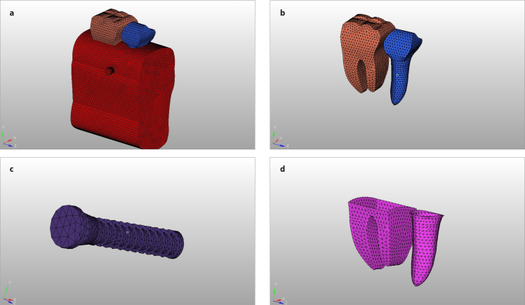
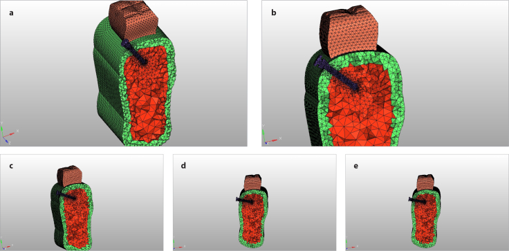
A FEM was created using a dedicated software (ANSYS Workbench 14.5, Canonsburg, PA, USA). The FEM was composed of five elements: 1- the mandibular second premolar and first permanent molar having 0.2 mm thickness of periodontal ligament and cancellous bone and 2 mm thickness of cortical bone (Figure 1); 2- MI model (diameter, length, and screw); 3- modeling of cortical and cancellous bones and thickness of periodontal ligament; 4- FEM of MI when placed into bone at various angulation (Figure 2); and 5- Young’s modulus and Poisson’s ratio for all constituent structures under experiment. The study was approved by the Institutional Ethics Committee, All India Institute of Medical Sciences, Jodhpur (AIIMS/IEC/2018/697).
Figure 1. a–d.
(a) FEM consisting of (b) tooth, (c) MI, (d) periodontal ligament and bone elements. FEM: finite element model
Figure 2. a–e.
FEM consisting of MI at different angulations: (a) 30°, (b) 45°, (c) 60°, (d) 75°, and (e) 90°. FEM: finite element model
MI: Mini-implant
The geometry of the FEM of the lower first molar and second premolar was determined using standard measurement (19). The periodontal ligament was replicated to a thickness of 0.2 mm around the root along with 0.15 mm thin cementum layer (20). Orthodontic MI made of pure titanium (diameter, 1.6 mm; length, 8 mm; thread ridge height, 0.2 mm; thread pitch, 0.6 mm) was modeled. The MI dimensions (Figure 3) were created on the basis of the research by Motoyashi et al. (21). Based on the classical theory of elasticity and for the ease of modeling, it was assumed that the constituent material was isotropic and homogeneous. The behavior of the constituent material was quantified by Poisson’s ratio and Young’s modulus as per the previous research (22). The material properties for MI, bone, and periodontal ligament are given in Table 1.
Figure 3.
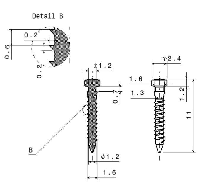
Schematic representation of implant design used in this finite element study
Table 1.
Material properties of constituent materials
| Materials | Young’s modulus (MPa) | Poisson’s ratio |
|---|---|---|
| Titanium | 110,000 | 0.35 |
| Cortical bone | 14,000 | 0.30 |
| Cancellous bone | 1,370 | 0.30 |
| Periodontal membrane | 69 | 0.45 |
| Tooth | 18,600 | 0.31 |
MPa: Megapascal
The site of placement of MI was assumed to be in between mandibular second premolar and first molar on the basis of a morphometric study (23). FEM was created with MI insertion at 30°, 45°, 60°, 75°, and 90° angulations, and at each angulation a horizontal load of 150, 200, and 250 g was applied (24). The boundary between the MI and the bone elements was secured to demarcate from other interfaces. Gap elements that existed between the MI and periodontal membrane were considered to be negligible. On the application of different loads at each angulation, stress values were calculated in all component structures and at the neck of the MI. Table 2 represents the number of nodes and elements created in the study.
Table 2.
Number of nodes and elements generated for each model
| Model | Elements | Nodes |
|---|---|---|
| Model30 | 140,039 | 27,564 |
| Model45 | 140,053 | 27,531 |
| Model60 | 140,247 | 27,594 |
| Model75 | 140,416 | 27,614 |
| Model90 | 175,121 | 33,319 |
RESULTS
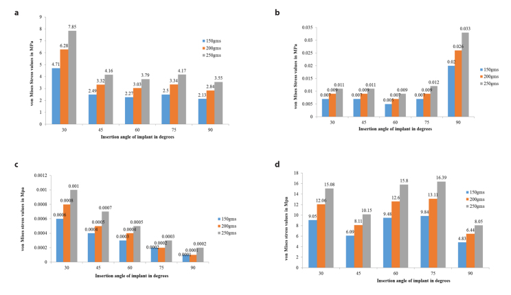
The von Mises stress distribution in the cortical bone, cancellous bone, periodontal ligament, and MI itself was assessed using a colored scale (Figure 4). Low and high stress values in the scale are depicted by blue and red color, respectively. Table 3 represents numerical values of von Mises stress in the cortical and cancellous bones, periodontal ligament, and MI at 30°, 45°, 60°, 75°, and 90° insertion angulations at varying loads. The von Mises stress values in the cortical bone were highest (4.71, 6.28, and 7.85 megapascal [MPa] at 150, 200, and 250 g, respectively) at 30° angulation (Figure 5). The values for other angulations were lower. The von Mises stress values in cancellous bone were highest (0.020, 0.026, and 0.033 MPa at 150, 200, and 250 g, respectively) at 90° angulation. The values were lowest for 60-degree angulation. Whereas the von Mises stress values in periodontal ligament were lowest (0.0001, 0.0001, and 0.0002 MPa at 150, 200, and 250 g, respectively) at 90° angulation, the values were low and comparable at 60- (0.0003, 0.0004, 0.0005 MPa at 150, 200, and 250 g, respectively) and 75- (0.0002, 0.0002, 0.0003 MPa at 150, 200, and 250 g, respectively) degree angulations and highest at 30° angulation.
Figure 4.
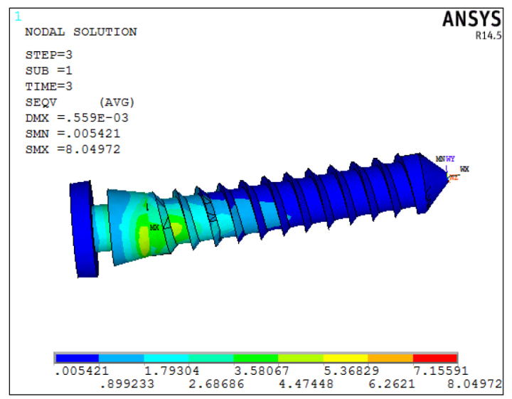
von Mises stress at various MI sites depicted by a different scheme of colors. MI: Mini-implant
Table 3.
Maximum von Mises stress values induced at various insertion angulations and different horizontal loads
| Horizontal load | ||||
|---|---|---|---|---|
|
| ||||
| 150 g | 200 g | 250 g | ||
|
| ||||
| Model | MI Insertion angulations | von Mises stress (MPa) | ||
| Cortical bone | 30 | 4.71144 | 6.28129 | 7.85241 |
| 45 | 2.49361 | 3.32481 | 4.15601 | |
| 60 | 2.27166 | 3.02887 | 3.78609 | |
| 75 | 2.50206 | 3.33608 | 4.1701 | |
| 90 | 2.1329 | 2.84387 | 3.5548 | |
| Cancellous bone | 30 | 0.0065 | 0.0087 | 0.0109 |
| 45 | 0.0066 | 0.0088 | 0.0110 | |
| 60 | 0.0053 | 0.0071 | 0.0089 | |
| 75 | 0.0070 | 0.0093 | 0.0116 | |
| 90 | 0.0196 | 0.0261 | 0.0327 | |
| Periodontal ligament | 30 | 0.000612 | 0.000817 | 0.001021 |
| 45 | 0.000396 | 0.000528 | 0.000660 | |
| 60 | 0.000286 | 0.000382 | 0.000477 | |
| 75 | 0.000153 | 0.000204 | 0.000255 | |
| 90 | 0.0000982 | 0.000131 | 0.000164 | |
| MI | 30 | 9.04785 | 12.0638 | 15.0798 |
| 45 | 6.0885 | 8.118 | 10.1475 | |
| 60 | 9.48337 | 12.643 | 15.8037 | |
| 75 | 9.83599 | 13.1147 | 16.3933 | |
| 90 | 4.8298 | 6.4397 | 8.0497 | |
MI: Mini-implant; MPa: Megapascal
Figure 5. a–d.
von Mises stress values induced at various insertion angulation in (a) cortical bone, (b) cancellous bone, (c) periodontal ligament, and (d) MI
MI: Mini-implant
The von Mises stress values in the MI were lowest (4.83, 6.44, and 8.04 MPa at 150, 200, and 250 g, respectively) at 90° angulation followed by 45° angulation, and the values were higher at 30°, 60°, and 75° insertion angulations. Stress values were found to be the highest within MI when compared with cortical bone, cancellous bone, and periodontal ligament. The least amount of stress was observed in the periodontal ligament at all angulations. Overall, the von Mises stresses in cortical bone, cancellous bone, periodontal ligament, and MI increased with an increase in the amount of the horizontal load at all angulations.
DISCUSSION
The FEM simulated the biomechanical force system that is applied clinically and allowed to evaluate the response of dentoalveolar system. Posterior region of the mandibular bone was chosen as a site of implant placement because previous studies have reported a lower success rate in mandible as compared with maxillary bone (5, 25). This is in contrast to dental implants where the opposite is true (3–5). Cortical bone thickness of 2 mm between second premolar and first permanent molar was modeled as this is the most common site of MI placement. Screw diameter greater than 1.8 mm usually requires larger inter-radicular space, whereas screw diameter less than 1.5 mm reduces the primary stability. Therefore, a screw diameter of 1.6 mm was chosen, which would provide sufficient mechanical properties without requiring a wide insertion space (26–28). It has been widely reported that the majority of the MIs have the ability to stand 100–200 g of horizontal load (early or immediate) with ease and the magnitude is sufficient for various tooth movements (29–32). The orthodontic force levels selected in this study were 150, 200, and 250 g, to simulate clinically viable conditions.
This study showed that von Mises stress values increased with increasing horizontal loading force. The forces considered in this study were within the optimum ranges for clinical conditions, such as individual canine retraction using horizontal component of force of 150 g or en masse retraction using horizontal component of force in the range of 200–250 g. Lin et al. (9) conducted a study and reported that the orthodontic force direction had no statistically significant effect on stress values in cortical bone. Hence, different directions of loading force were not taken into consideration in this study. Critical stress curves as drawn in the study by Li et al. (33) for overload and underload resorption demonstrated that cortical bone resorption because of overloading was seen in areas with von Mises stress greater than 25–28 MPa. The authors suggested that injury to the periodontal membrane during MI insertion may cause overload bone resorption especially when the integrity of the root is maintained. This overloading could be attributed to MI failure (33). The findings of Robert et al. (30) also suggest that forces between 1 and 3 N do not affect implant stability. Zhang et al. (16) theorize that within the implant-cortical bone spongy bone system, higher stresses are received by cortical bone primarily because of its high modulus of elasticity. Similar findings were also noticed in this study as the stress in the cortical bone was higher in comparison with cancellous bone.
Regarding the effect of angulations on von Mises Stress, the increase in MI insertion angulation appears to be inversely proportional to stress values produced in the cortical bone. The highest stress values were observed in the cortical bone when the MI insertion angulation was at 30°. The stress values in the cortical bone were minimum at 90° angulation and values at 60°, 75°, and 45° were in between. Previous studies have shown that cortex thickness primarily governs the transmission of force from mini-screw to bone, and cancellous bone thickness plays a minor role (34, 35). More importantly, cortical bone is more resistant to distortion and can withstand higher loads mainly because of its higher modulus of elasticity. Dense cortical bone is advantageous from the primary stability perspective; however, if the site lacks sufficient preparation, secondary stability can be significantly compromised because of increased compression of bone (36). Primary stability is imperative in early healing and remodeling phase, especially when there is early loading of the implant.
The stress values in cancellous bone were of the lower magnitude when compared with cortical bone. The minimum stress values were detected in cancellous bone when the implant was at 60° angulation. The stress was maximum at 90° angulation. The long-term success of the implant after the healing phase and during the loading phase is primarily dependent on secondary stability. No attempt was made to simulate secondary stability in this study to avoid complex configuration. Reduced stress in cancellous bone can be a factor that enhances secondary stability, but this needs further research. The von Mises stress in the periodontal ligament was much lower than both bony elements.
The von Mises stress in the MI was mostly present at the neck of the implant close to bone-implant interface. The minimum stress value was found in the bone when the implant was at 90° angulation. Considering that MIs are made of pure titanium having superior properties, the stress values at all angulations were low enough to presume that there may not be implant breakage up to 250 g of horizontal force. Excessive stress concentrations were detected in the MI at the cervical margin around first few threads. Similar findings have been presented by Meijer et al. (37), Barbier et al. (38), and Clelland et al. (39). However, Vasquez et al. (40) used a dental implant for anchorage in their study and contested this point that even though the stress concentration was localized in the cervical margin and first threads, these stresses are of very low magnitude and inadequate to cause the failure of the implant. Consequently, the osseo-integrated dental implant may act as potential anchor units as they are better suited to withstand orthodontic forces. The results of this study are in agreement with the research by Jasmine et al. (41) who found that at a horizontal load of 200 g, maximum stress values were within the MI, followed by cortical bone and least in the cancellous bone.
There has been a considerable debate whether the insertion angulation should be perpendicular or angulated. Jasmine et al.(41)reported that a decrease in stress values was observed in both MI and cortical bone as the insertion angulation increased from 30° to 90°. They concluded that ideal MI insertion angulation should be at 90° for enhanced stability. The FEA by Perillo et al. (24) also advocated that placing mini-screws at 90° angle would result in improved stability than at angulation lesser or greater than 90°. On the contrary, as the insertion angle affects the primary stability the least, oblique or a diagonal insertion of MI is advantageous over perpendicular insertion because of its added biomechanical advantages (15). This argument is supported by the study by Wilmes et al. (15) who suggested that oblique placement may lead to a slightly greater primary stability, especially in the areas with poor or reduced bone quality. To achieve higher insertion torque values, insertion angulation ranging from 60° to 70° have also been suggested (15). This insertion angulation may also prove to be beneficial whenever there is insufficient inter-radicular space for MI placement and further help in the aversion of root contact.
FEM was constructed on the basis of the assumption that cortical and trabecular bones were isotropic and homogeneous. Other structures such as osteons, Haversian canals, and interstitial lamellae were not modeled as this would have further complicated the analysis. With the current knowledge, it is difficult to exactly predict the changes that occur with the passage of time with the same loading conditions. This study is a predictive analysis and must be used as a reference to aid clinical judgment.
CONCLUSION
The following conclusions were drawn from this FEM study:
In the cortical bone, MI, and periodontal ligament, the von Mises stress value was least at 90° insertion angulation.
The von Mises stress values were found to be highest in cortical bone and periodontal ligament when the MI was angulated at 30°.
The von Mises stress values in cancellous bone were found to be highest and lowest at 90 and 60°, respectively.
When applied with a horizontal load, placing the MI at 90° seems to be the ideal angulation. The von Mises stress values at 60°, 75°, and 90° insertion angulations are higher.
The increasing loads cause an increase in stress levels. Even though the horizontal load of 250 g has the maximum stress levels, it is under the levels that can cause overloaded bone resorption and in turn MI failure.
Main points.
In this finite element model, von Mises stress values were found to be least at 90° in all structures except cancellous bone.
Perpendicular placement of mini-implant appears to be the ideal insertion angulation.
Increase in load values causes an increase in the stress values at all angulations.
Footnotes
Ethics Committee Approval: This study was approved by Institutional Ethics Committee, All India Institute of Medical Sciences, Jodhpur (AIIMS/IEC/2018/697).
Informed Consent: Informed consent is not necessary due to the nature of this study.
Peer-review: Externally peer-reviewed.
Author Contributions: Conception – K.D., V.K.C., P.T.; Design – V.K.C., K.D., P.T.; Supervision – K.D., V.K.C.; Resources – M.S., A.M.; Materials –M.S., A.M.; Data Collection and/or Processing – M.S., A.M.; Analysis and/or Interpretation – V.K.C., M.S., A.M., A.C.; Literature Search – M.S., A.M.,V.K.C., A.C.; Writing Manuscript – V.K.C., M.S., A.M., A.C., A.C., P.T.; Critical Review – V.K.C., K.D., M.S., A.M., A.C., P.T.
Conflict of Interest: The authors have no conflict of interest to declare.
Financial Disclosure: The authors declared that this study has received no financial support.
REFERENCES
- 1.Roberts WE, Helm FR, Marshall KJ, Gongloff RK. Rigid endosseous implants for orthodontic and orthopedic anchorage. Angle Orthod. 1989;59:247–56. doi: 10.1043/0003-3219(1989)059<0247:REIFOA>2.0.CO;2. [DOI] [PubMed] [Google Scholar]
- 2.Cope JB. Temporary anchorage devices in orthodontics: A paradigm shift. Semin Orthod. 2005;11:3–9. doi: 10.1053/j.sodo.2004.11.002. [DOI] [Google Scholar]
- 3.Kuroda S, Sugawara Y, Deguchi T, Kyung HM, Takano-Yamamoto T. Clinical use of miniscrew implants as orthodontic anchorage: Success rates and postoperative discomfort. Am J Orthod Dentofacial Orthop. 2007;131:9–15. doi: 10.1016/j.ajodo.2005.02.032. [DOI] [PubMed] [Google Scholar]
- 4.Park HS, Jeong SH, Kwon OW. Factors affecting the clinical success of screw implants used as orthodontic anchorage. Am J Orthod Dentofacial Orthop. 2006;130:18–25. doi: 10.1016/j.ajodo.2004.11.032. [DOI] [PubMed] [Google Scholar]
- 5.Cheng SJ, Tseng IY, Lee JJ, Kok SH. A prospective study of the risk factors associated with failure of mini-implants used for orthodontic anchorage. Int J Oral Maxillofac Implants. 2004;19:100–6. [PubMed] [Google Scholar]
- 6.Jiang L, Kong L, Li T, Gu Z, Hou R, Duan Y. Optimal selections of orthodontic mini-implant diameter and length by biomechanical consideration: A three-dimensional finite element analysis. Adv Eng Software. 2009;40:1124–30. doi: 10.1016/j.advengsoft.2009.05.008. [DOI] [Google Scholar]
- 7.Wu T, Kuang S, Wu C. Factors associated with the stability of mini-implants for orthodontic anchorage: A study of 414 samples in Taiwan. J Oral Maxillofac Surg. 2009;67:1595–9. doi: 10.1016/j.joms.2009.04.015. [DOI] [PubMed] [Google Scholar]
- 8.Lai TT, Chen M. Factors affecting the clinical success of orthodontic anchorage: Experience with 266 temporary anchorage devices. J Dent Sci. 2014;9:49–55. doi: 10.1016/j.jds.2013.02.010. [DOI] [Google Scholar]
- 9.Lin TS, Tsai FD, Chen CY, Lin LW. Factorial analysis of variables affecting bone stress adjacent to the orthodontic anchorage mini-implant with finite element analysis. Am J Orthod Dentofacial Orthop. 2013;143:182–9. doi: 10.1016/j.ajodo.2012.09.012. [DOI] [PubMed] [Google Scholar]
- 10.Buchter A, Wiechmann D, Gaertner C, Hendrik M, Vogeler M, Wiesmann HP, et al. Load related bone modelling at the interface of orthodontic microimplants. Clin Oral Implants Res. 2006;17:714–22. doi: 10.1111/j.1600-0501.2006.01233.x. [DOI] [PubMed] [Google Scholar]
- 11.Wiechmann D, Meyer U, Buchter A. Success rate of mini and micro-implants used for orthodontic anchorage: a prospective clinical study. Clin Oral Implants Res. 2007;18:263–7. doi: 10.1111/j.1600-0501.2006.01325.x. [DOI] [PubMed] [Google Scholar]
- 12.Miyawaki S, Koyama I, Inoue M, Mishima K, Sugahara T, Yamamoto T. Factors associated with the stability of titanium screws placed in the posterior region for orthodontic anchorage. Am J Orthod Dentofacial Orthop. 2003;124:373–8. doi: 10.1016/S0889-5406(03)00565-1. [DOI] [PubMed] [Google Scholar]
- 13.Motoyashi M, Yoshida T, Ono A, Shimizu N. Effect of cortical bone thickness and implant placement torque on stability of orthodontic mini-implants. Int J Oral Maxillofac Implants. 2007;22:779–84. [PubMed] [Google Scholar]
- 14.Liu TC, Chang CH, Wong TY, Liu JK. Finite element analysis of miniscrew implants used for orthodontic anchorage. Am J Orthod Dentofacial Orthop. 2012;141:468–76. doi: 10.1016/j.ajodo.2011.11.012. [DOI] [PubMed] [Google Scholar]
- 15.Wilmes B, Su YY, Drescher D. Insertion angle impact on primary stability of orthodontic mini-implants. Angle Orthod. 2008;78:1065–70. doi: 10.2319/100707-484.1. [DOI] [PubMed] [Google Scholar]
- 16.Zhang Y, Zhang D, Feng CJ. A three-dimensional finite element analysis for the biomechanical characteristics of orthodontic anchorage micro-implant. Shanghai Kou Qiang Yi Xue. 2005;14:281–3. [PubMed] [Google Scholar]
- 17.Shalak R. Biomechanical considerations in osseointegrated prosthesis. J Prosthet Dent. 1983;49:843–8. doi: 10.1016/0022-3913(83)90361-X. [DOI] [PubMed] [Google Scholar]
- 18.Middleton J, Jones M, Wilson A. The role of the periodontal ligament in bone modeling: the initial development of a time dependent finite element model. Am J Orthod Dentofacial Orthop. 1996;109:155–62. doi: 10.1016/S0889-5406(96)70176-2. [DOI] [PubMed] [Google Scholar]
- 19.Nelson SJ, Ash MM. Wheeler’s dental anatomy, physiology and occlusion. 9th ed. St Louis: Saunders Elsevier; 2010. p. 13. [Google Scholar]
- 20.Newman MG, Takei HH, Carranza FA. Carrranza’s Clinical Periodontology. 9th ed. St. Louis: Saunders; 2002. p. 54. [Google Scholar]
- 21.Motoyashi M, Ueno S, Okazaki N, Shimizu N. Bone stress for a mini-implant close to the roots of adjacent teeth.- A 3D Finite element analysis. Int J Oral Maxillofac Surg. 2009;38:363–8. doi: 10.1016/j.ijom.2009.02.011. [DOI] [PubMed] [Google Scholar]
- 22.Motoyoshi M, Yano S, Tsuruoka T, Shimizu N. Biomechanical effect of abutment on stability of orthodontic mini-implant: A finite element analysis. Clin Oral Impl Res. 2005;16:480–5. doi: 10.1111/j.1600-0501.2005.01130.x. [DOI] [PubMed] [Google Scholar]
- 23.Deguchi T, Nasu M, Murakami K, Yabuuchi T, Kamioka H, Takano-Yamamoto T. Quantitative evaluation of cortical bone thickness with computed tomographic scanning for orthodontic implants. Am J Orthod Dentofacial Orthop. 2006;129:721.e7–12. doi: 10.1016/j.ajodo.2006.02.026. [DOI] [PubMed] [Google Scholar]
- 24.Perillo L, Jamilian A, Shafieyoon A, Karimi H, Cozzani M. Finite element analysis of miniscrew placement in mandibular alveolar bone with varied angulations. Eur J Orthod. 2015;37:56–9. doi: 10.1093/ejo/cju006. [DOI] [PubMed] [Google Scholar]
- 25.Kuroda S, Yamada K, Deguchi T, Hashimoto T, Kyung HM, Takano-Yamamoto T. Root proximity is a major factor for screw failure in orthodontic anchorage. Am J Orthod Dentofacial Orthop. 2007;131:S68–S73. doi: 10.1016/j.ajodo.2006.06.017. [DOI] [PubMed] [Google Scholar]
- 26.Lietz T. Mini-screws: Aspects of assessment and selection among different systems. In: Ludwig B, Baumgaertel S, Bowman SJ, editors. Mini-implants in orthodontics: Innovative achorage concepts. London: Quintessence; 2008. pp. 11–72. [Google Scholar]
- 27.Park HS, Jeong SH, Kwon OW. Factors affecting the clinical success of screw implants used as orthodontic anchorage. Am J Orthod Dentofacial Orthop. 2006;130:18–25. doi: 10.1016/j.ajodo.2004.11.032. [DOI] [PubMed] [Google Scholar]
- 28.Sung JH, Kyung HM, Bae SM, Park HS, Kwon OW, McNamara JA. Microimplants in Orthodontics. Daegu: Dentos; 2006. pp. 12–3. [Google Scholar]
- 29.Buchter L, Wiechmann D, Koerdt S, Wiesmann HP, Piffko J, Meyer U. Load-related implant reaction of mini-implants used for orthodontic anchorage. Clin Oral Impl Res. 2005;16:473–9. doi: 10.1111/j.1600-0501.2005.01149.x. [DOI] [PubMed] [Google Scholar]
- 30.Roberts WE, Marshall KJ, Mozsary PG. Rigid endosseous implant utilized as anchorage to protract molars and close an atrophic extraction site. Angle Orthod. 1990;60:135–52. doi: 10.1043/0003-3219(1990)060<0135:REIUAA>2.0.CO;2. [DOI] [PubMed] [Google Scholar]
- 31.Kanomi R. Mini-implant for orthodontic anchorage. J Clin Orthod. 1997;31:763–7. [PubMed] [Google Scholar]
- 32.Yamaguchi M, Inami T, Ito K, Kasai K, Tanimoto Y. Mini-Implants in the anchorage armamentarium: New paradigms in the orthodontics. Int J Biomater. 2012;2012 doi: 10.1155/2012/394121. 302825. [DOI] [PMC free article] [PubMed] [Google Scholar]
- 33.Li J, Li H, Shi L, Fok SLA, Ucer C, Devlin H, et al. A mathematical model for simulating the bone remodeling process under mechanical stimulus. Dent Mater. 2007;23:1073–8. doi: 10.1016/j.dental.2006.10.004. [DOI] [PubMed] [Google Scholar]
- 34.Melsen B, Verna C. Miniscrew implants: The Aarhus anchorage system. Semin Orthod. 2005;11:24–31. doi: 10.1053/j.sodo.2004.11.005. [DOI] [Google Scholar]
- 35.Stahl E, Keilig L, Abdelgader I, Jager A, Bourauel C. Numerical analyses of biomechanical behaviour of various orthodontic anchorage implants. J Orofac Orthop. 2009;70:115–27. doi: 10.1007/s00056-009-0817-y. [DOI] [PubMed] [Google Scholar]
- 36.Baumgaertel S. Predrilling of the implant site: is it necessary for orthodontic mini-implants? Am J Orthod Dentofacial Orthop. 2010;137:825–9. doi: 10.1016/j.ajodo.2008.06.038. [DOI] [PubMed] [Google Scholar]
- 37.Meijer GJ, Starmans FJM, de Putter C, Van Blitterswrjk CA. The influence of a flexible coating on the bone stress around dental implants. J Oral Rehabil. 1995;22:105–11. doi: 10.1111/j.1365-2842.1995.tb00243.x. [DOI] [PubMed] [Google Scholar]
- 38.Barbier L, Sloten JV, Krzeinski G, Schepers E. Finite element analysis of non-axial versus axial loading of oral implants in the mandible of the dog. J Oral Rehabil. 1998;25:847–58. doi: 10.1046/j.1365-2842.1998.00318.x. [DOI] [PubMed] [Google Scholar]
- 39.Clelland NL, Ismail YH, Zaki HS, Pipko D. Three-dimensional finite element stress analysis in and around the screw-vent implant. Int J Oral Maxillofac Implants. 1991;6:391–2. [PubMed] [Google Scholar]
- 40.Vasquez M, Calao E, Becerra F, Becerra F, Ossa J, Enriquez C, et al. Initial stress difference between sliding and sectional mechanics with an endosseous implant as anchorage: A 3 dimensional finite element analysis. Angle Orthod. 2001;71:247–56. doi: 10.1043/0003-3219(2001)071<0247:ISDBSA>2.0.CO;2. [DOI] [PubMed] [Google Scholar]
- 41.Jasmine MI, Yezdani AA, Tajir F, Venu RM. Analysis of stress in bone and microimplants during en-masse retraction of maxillary and mandibular anterior teeth with different insertion angulations: A 3-dimensional finite element analysis study. Am J Orthod Dentofacial Orthop. 2012;141:71–80. doi: 10.1016/j.ajodo.2011.06.031. [DOI] [PubMed] [Google Scholar]


