Abstract
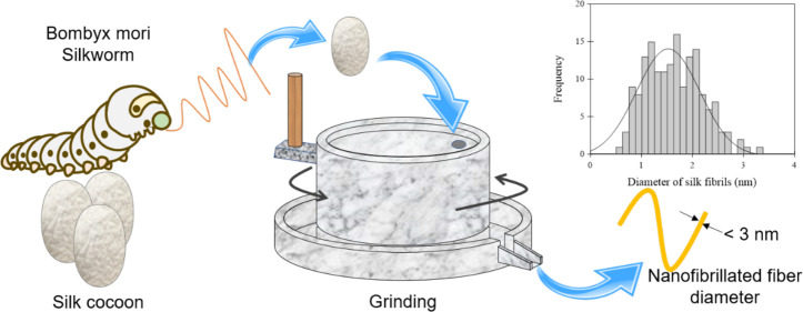
Silk fibroin, a biodegradable component of silk, is increasingly used for various applications and studied intensively. Recently, a technique for preparing nanofibers without using chemicals has been gaining attention from the environmental impact and safety perspectives. This study focuses on the structure observation of ground silk fibroin (GF) prepared using a grinding method, which is a physical nanofibrillation method. The fabricated nanofiber samples were examined in detail using the X-ray diffraction (XRD), differential scanning calorimetry (DSC), micro Raman spectroscopy, and atomic force microscopy (AFM) techniques. The nanofibrillated structures were observed in both GF and regenerated silk fibroin (RF) samples prepared using the conventional method. As results, AFM images showed that the nanofibril diameter of GF was about 1.64 nm and that of RF was about 0.32 nm. Methanol treatment induced a structural transition from a random coil to a β-sheet for the RF film, but it had no effect on the GF film. Thus, it is suggested that the grinding method provides not only ultrafine silk fibroin nanofibers without using toxic reagents but also resistance to reagents such as methanol.
1. Introduction
Silk is the only long fiber among natural fibers and has excellent characteristics such as luster, dyeability, and moisture retention. It has been long used for clothing and has been part of human existence since ancient times. Silk fibroin, which is the main component of silk, is a biodegradable polymer of natural origin and has high biocompatibility. Thus, it is used not only as a fiber for clothing but also as a biocomposite, an environment friendly material.1−4 Recently, silk fibroins have been gaining attention, particularly in the field of regenerative medicine for use as scaffolds and membranes in tissue repair.5−7
As silk fibroin is generally insoluble in water, it can be dissolved in a highly concentrated neutral salt solution such as aqueous solutions of calcium chloride, lithium bromide, or formic acid. An aqueous fibroin solution is obtained from the dialysis of the solution.8,9 The aqueous regenerated fibroin (RF) solution has a random coil or α-helix type structure; however, when it is immersed in polar solvents, such as methanol and ethanol, the higher order structure is transformed to an antiparallel β-sheet structure.10 A similar transition also occurs under heat treatment.11,12 The gelation of the aqueous RF solution easily proceeds due to the unstable structure of the random coil or α-helix in water. The transition from the random coil to the antiparallel β-sheet occurs during gelation.13−15 Temperature and pH, as well as the amounts of calcium ions and polyethylene oxide (PEO), affect the gelation of the fibroin.16 As described above, an organic solvent or toxic chemical is needed to prepare an aqueous RF solution using the conventional method. This is how traditional approaches chemically dissolve silk fibroin. In a previous study, Zhao et al.17 used the ultrasonic method to fabricate the silk fibroin nanofibers, but the fabrication process was slow and many fibers with non-uniform diameters of more than 1 μm were observed. Recently, a study has succeeded in producing an aqueous fibroin solution directly from silkworm cocoons by grinding without utilizing any organic solvent.18,19 Hence, it is a physical nanofibrillation method, not a chemical one. The fibroin film, which was prepared using the ground silk fibroin (GF) solution obtained by grinding, had superior mechanical and thermal properties compared with those prepared from RF solutions. Moreover, it was found that the grinding process could microfibrillate the fibroins while maintaining the β-sheet structure without dissolving them. However, there are only a few studies that investigate the relationship between the nanostructure and higher order structures of silk fibroins produced using the grinding method.
As GF can be produced simply and chemical-free, this process is expected to be applied in many fields including the field of tissue engineering where biocompatibility is required. Therefore, it is interesting to examine in detail and compare the fibril diameter and surface morphology of finely fibrillated silk fibroins produced using the physical nanofibrillation grinding method with those produced using the conventional chemically nanofibrillation method. This study aimed at investigating the characterization of ground silk fibroin through comparison of nanofibroin and higher order structures.
2. Experimental Section
2.1. Materials and Preparation of Silk Fibroin Solutions
The cocoons of Bombyx mori (silkworm) supplied from Nagasuna Mayu Inc. in Japan were used as a raw material in this experiment. To extract fibroin, sericin had to be removed; thus, the cocoons were boiled in a 0.9 wt % aqueous sodium carbonate solution at 95 °C for 120 min and the solution was then dried to obtain purified fibroin. The production of RF followed the method of Yamada et al.12 First, 1 g of purified fibroin was completely dissolved in 20 mL of 60 wt % lithium bromide solution and stirred at 60 °C using a magnetic stirrer for 4 h. Subsequently, the dissolved fibroin solution was placed in a cellulose tube and dialyzed with tap water at room temperature for 1 week. The aqueous RF solution that was obtained after the dialysis and the gelled regenerated fibroin (RFG: regenerated fibroin gel) solution at room temperature were used as sample solutions in this experiment. The GF was prepared according to the method presented by Okahisa et al.18 The purified fibroin powder was washed with distilled water to prepare a mixture of purified fibroin and water. A 1 wt % fibroin suspension was prepared by passing four times through a grinder (MKCA 6-3, Masuko Sangyo Co., Japan) with a rotating grinding stone (MKGC 6-120, Masuko Sangyo Co., Japan) at 1500 rpm.
2.2. Characterizations
To evaluate the crystalline structures of silk fibroin films, X-ray diffraction (XRD) patterns were obtained using an RINT-2500 (Rigaku Co., Tokyo, Japan). The camera distance was fixed at 60.76 mm, and the exposure time was 30 min. Differential scanning calorimetry (DSC, DSC-60A Plus, Shimadzu Co. Ltd., Japan) was also used for evaluating the crystalline structure of each silk fibroin film. Differential scanning calorimetry heating run curves were recorded at 5 °C/min from 10 to 250 °C under a nitrogen gas flow rate of 100 mL/min. The amount of sample used for DSC was approximately 5 mg. Laser Raman confocal microscopy (LabRAM HR-800, HORIBA, Ltd., Japan) with a 633 nm excitation laser source was used for the analysis of the chemical structures of silk fibroin films prepared from each method. The exposure time was set at 5.0 s, and the number of scans was set at 5 for single-spectrum measurements. Cast films prepared on glass substrates and naturally dried at room temperature were used as samples for XRD, DSC, and micro Raman spectroscopy measurements.
Atomic force microscopy (AFM, AFM 5100 N, Hitachi High-Tech Science Co., Tokyo, Japan) was used to observe the surface morphology of the sample. The measurement mode was the dynamic force mode (DFM). The cantilever tip used was an OMCL-AC200TS (Olympus, Tokyo, Japan). The nanostructure of the fibroin molecules was observed over a 1 × 1 μm area. Samples for AFM analysis were prepared by casting the fibroin solution, diluted with pure water, on a mica substrate according to the method presented by Yamada et al.12 Each dilute solution was allowed to stand for a certain time, and the supernatant liquids were then used for fabricating monolayers. All AFM samples were used after natural drying at room temperature.
3. Results and Discussion
X-ray diffraction measurement is a useful technique to determine the crystal structure of silk fibroin. In general, raw silk fibroin has two forms, Silk I and Silk II. Silk I has a water-soluble helical structure that mainly exists in the silk gland before spinning and undergoes a structural change to a water-insoluble Silk II structure, which consists of a β-sheet type. The transition from Silk I to Silk II is known to occur due to a number of factors, including the removal of water molecules and calcium ions and the external forces during the natural spinning process.20Figure 1 shows the results of XRD measurements for each silk fibroin film and raw silk fibroin. The diffraction peaks were observed at 20.6° and 24.4° for RFG, GF, and raw silk fibroin. Generally, diffraction peaks between 20° and 21° indicate the Silk II structure, which is a β-sheet form, while diffraction peaks between 24° and 25° indicate a Silk I structure, which is a helical silk protein structure.21,22 Therefore, RFG and GF are considered a mixed state of Silk I and Silk II crystals. In addition, it was evident that the crystallinity of these films increased according to the following order: raw silk fibroin < RFG < GF. In contrast, RF was considered to have an almost amorphous structure as it did not show significant diffraction peaks.
Figure 1.
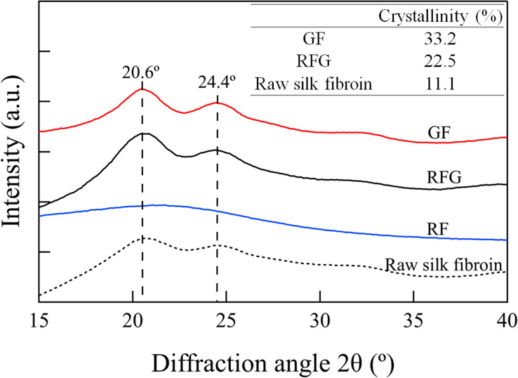
X-ray diffractograms of each sample.
Figure 2 shows typical DSC curves of each silk fibroin film from 10 to 250 °C. From the DSC results, the endothermic peak between 40 and 140 °C, which was due to the evaporation of bound water, was observed in each curve.23,24 The small endothermic peak at approximately 200 °C corresponded to the glass transitions. The exothermic peak in the RF curve was observed at approximately 220 °C, which means that the crystallization was induced by the effect of heating. Motta et al.24 and Lu et al.25 reported the crystallization peak of regenerated silk fibroin at approximately 213 °C, while Um et al.9 reported it at approximately 228 °C. However, the same peak was not observed in the RFG and GF curves. These results mean that the amorphous structure of RF was transformed to an antiparallel β-sheet structure and that RFG and GF had been sufficiently crystallized.
Figure 2.
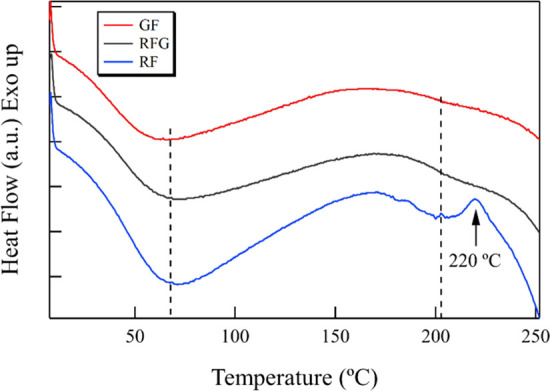
Typical DSC curves of each silk sample.
Each sample film was analyzed using micro Raman spectroscopy to identify differences in the higher order structures of raw silk fibroin, GF, and RFG samples. Figure 3 shows the Raman spectra of each silk fibroin film, while Table 1 summarizes the Raman band assignments for the silk fibroins employed in this research. The peaks near 3285 cm–1, which corresponds to N–H stretching in β-sheets, were observed in the RFG and GF spectra, while no peak could be observed in the same area for RF.26 The peaks near 3062, 2934, and 2876 cm–1 were observed in each spectrum; however, only the peak in RF was shifted to a lower wavenumber at approximately 5 cm–1. The peak near 1666 cm–1, which corresponds to the C=O stretching in β-sheets of amid I,27 was observed in the RFG and GF spectra, while there a was small and broad peak observed in the RF spectrum. In addition, the peaks near 1267 and 1230 cm–1, which correspond to the β-sheets of amid III,27 were observed in the RFG and GF spectra, while there was no peak in the same area for RF. These results indicate that the RFG and GF have crystallized regions. This result is in good agreement with the XRD results. However, it should be noted that the Silk I and Silk II peaks could not be separated from the amide I peak in the Raman spectra. According to Monti et al.27 the Raman peaks of random coil conformation and the Silk I form are very similar and cannot be distinguished. Furthermore, Raman spectroscopy is not suitable for characterizing the Silk I form in the presence of a random coil conformation. Therefore, a successful combination of XRD and Raman measurements will allow us to identify the detailed structure of silk fibroin. In addition, only GF has a peak at 1401 cm–1; RF and RFG had no peak in this region. The polarized intensity ratio of the Raman bands at 1401 cm–1 is well correlated with the molecular orientation of β-sheets in silk fibers,28 and the lattice vibration of crystals is generally observed in lower wave numbers. The resulting crystallinity determined by XRD also indicates that GF was more crystallized than RFG. The Raman spectra results show that RFG had a higher order structure, which was intermediate between RF and GF. Furthermore, similar to previous studies,13−15 it was shown that the RFG was transformed from a random coil type to an antiparallel β-sheet structure through gelation. It was also reported that silk fibroins maintain the raw silk fibroin structure without sericin.18 Results from the Raman microscopy, XRD, and DSC indicate that RF had an amorphous structure, while both RFG and GF had a crystalline structure; however, RFG and GF had slightly different conditions.
Figure 3.
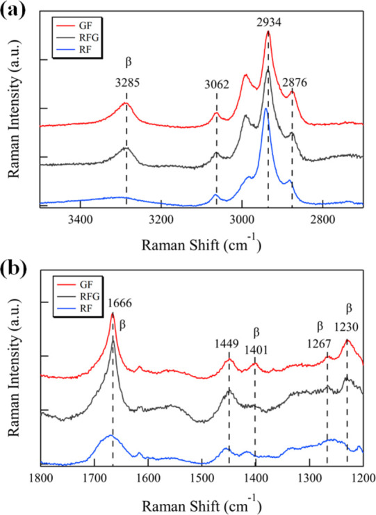
Raman spectra of each sample in the wavenumber range of (a) 3500–2700 and (b) 1800–1200 cm–1.
Table 1. Raman Band Assignments for Silk Fibroin.
| Raman
band (cm–1) |
||||
|---|---|---|---|---|
| GF | RFG | RF | intensitya | assignment |
| 1230 | 1230 | m | amide III (β-sheets) | |
| 1267 | 1267 | m | amide III (β-sheets, disordered) | |
| 1401 | m | β-sheets in silk fibers | ||
| 1449 | 1449 | 1455 | m br | CH2-, CH3-bending modes |
| 1666 | 1666 | 1671 | vs | amide I (β-sheets) |
| 2876 | 2876 | 2882 | s | CH3 symmetric stretching |
| 2934 | 2934 | 2941 | vs | CH3 asymmetric stretching |
| 3062 | 3062 | 3065 | m | C–N–H bending |
| 3285 | 3285 | m br | N–H stretching (β-sheets) | |
s, strong; m, medium; br, broad; and v, very.
In previous studies,12,29 the diameter of the silk fibroin molecular chain has been measured by casting its dilute solution onto a mica substrate to produce monolayers, which have been estimated by measuring the height of each molecular chain by AFM. Thus, to evaluate the difference of the nanostructure of silk fibroin (RF and RFG) chemically dissolved in aqueous lithium bromide from that of silk fibroin (GF) physically fibrillated through grinding, monolayers from each dilute solution were fabricated on a mica substrate for AFM measurements. It should be noted that each dilute solution was allowed to stand for a certain time and the supernatant liquids were then used for fabricating monolayers. Figure 4 shows the AFM results on the surface morphology of each sample. The upper photos are the morphology images, while the lower photos are the phase images. In all samples, nanosized fibrils with thread-like structures were observed; however, the shapes of RF, RFG, and GF fibers looked different as shown in the AFM results. Compared to GF, RF and RFG had finer thread-like structures, which correspond to silk fibroin molecular chains.12,29 Choi et al.30 found no correlation between surface roughness and crystallization of the fibroin thin film when treated with ethanol or methanol as observed through AFM. In contrast, Yamada et al.12 reported that when an ultrathin fibroin film, prepared with an aqueous solution of CaCl2, was treated with methanol, the network structure shrinks and changes to a β-sheet structure having a height of 1.3 nm. To confirm whether RF would exhibit the same morphology as GF when the RF structure converts to an antiparallel β-sheet, the RF film was treated with methanol and then observed through AFM. In addition, a methanol treatment was similarly performed on a GF film as a comparative control experiment, which was also subjected to AFM analysis.
Figure 4.
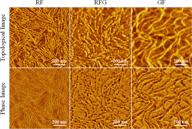
AFM images of each sample surface: upper photos, topological images; lower photos, phase images.
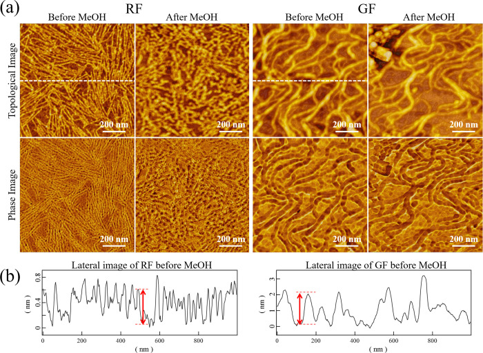
Figure 5a shows the AFM results for RF and GF before and after methanol (MeOH) treatment. Figure 5b shows a cross-sectional graph of the topological images of RF and GF before methanol treatment in the dotted line of Figure 5a. The red arrows correspond to typical single-molecule heights. In the RF film, the appearance was clearly different before and after methanol treatment. However, for the GF film, the influence of the methanol treatment on its morphology was hardly observed. Thus, the fiber diameter was calculated from the AFM image data to compare the fiber shapes of both samples before and after methanol treatment. As AFM was used in previous researches,12,29 it gives the correct value in the Z direction (height) but does not give accurate values in the XY directions due to the influence of the radius of the cantilever tip on horizontal resolution, particularly when the object to be observed is smaller than the curvature radius of the tip. Thus, only the height of the thread-like structures was calculated in this research.
Figure 5.
(a) AFM images of the RF and GF sample surfaces before and after methanol (MeOH) treatment, and (b) cross-sectional graphs of RF and GF before methanol treatment in the dotted line of (a).
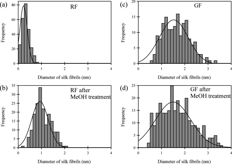
Figure 6 and Table 2 show the average diameters of the fibroin fibers of both samples before and after methanol treatment. The average diameter of RF before methanol treatment was 0.32 nm with a standard deviation of 0.15. Previous work of Inoue et al.29 found the height of S. c. ricini wild silk fibroin on a mica surface to be 0.4 nm, and previous work of Yamada et al.12 also found the height of Bombyx mori silk fibroin on a mica surface to be 0.3–0.4 nm, which were in good agreement with the 0.32 nm diameter of the RF measured in this research. In contrast, the average diameter of GF was 1.64 nm with a standard deviation of 0.55. Although the mean diameter of GF was larger than that of RF, ultrafine GF nanofibrils of 2 nm or less could be obtained using the grinder method. On the other hand, the average diameter of RF after methanol treatment was 1.07 nm with a standard deviation of 0.36. The average diameter after treatment was about 3.3 times larger than that before methanol treatment. According to a previous research,12 the thickness of a β-sheet is approximately 0.57 nm based on the molecular structure of the antiparallel β-sheet. Therefore, the fiber structure observed in this study, which has a diameter of 1.07 nm, possibly consisted of a couple of antiparallel β-sheets. However, the average diameter of GF after methanol treatment was 1.84 nm with a standard deviation of 0.71. There was no substantial change in the mean diameter of GF before and after methanol treatment. It should be noted that the surface morphology hardly changed based on AFM observations even when the methanol treatment was performed on a random coil-type ultrathin film, which was not only composed of a single molecular chain but also of aggregated chains.12,30 Thus, it was assumed that the surface morphology change due to methanol treatment was hardly observed because the GF fiber, which was obtained through grinding, was formed from several fibroin molecular chains with the β-sheet structure instead of a single-fibroin molecular chain with the random-coil structure. Considering the XRD, DSC, and Raman microscopy results, the increase in the RF fiber diameter after methanol treatment was due to the transition from the random coil type to the antiparallel β-sheet structure.12 More recently, Liang et al.31 reported that nanofibrils with several tens of nanometers in diameter could be made from raw silk fibroin using a mill and homogenizer. However, our study succeeded in fabricating ultrafine silk fibroin nanofibers with a diameter of approximately 1.6 nm with the β-sheet structure through physical microfibrillation grinding. We believe that the structure of the ultrafine nanofibrils, which is similar to that of the raw silk fibroin, leads to heat resistance and excellent mechanical properties as shown in previous research.18,19 Since high mechanical properties such as tensile modulus and strength are important considerations in the development of silk fibroin films and scaffolds for tissue engineering applications, silk fibroin nanofibers with the β-sheet structure obtained in this research have potential applications in scaffolds. In addition, the GF fiber was found to have a nearly β-sheet structure where it was not affected by the methanol treatment.
Figure 6.
Frequency distribution diagram of fiber diameter, (a) untreated RF, (b) MeOH treated RF, (c) untreated GF, and (d) MeOH-treated GF.
Table 2. Average Diameters and SD Values of RF and GF.
| parameter | RF | RF after MeOH | GF | GF after MeOH |
|---|---|---|---|---|
| dave (nm) | 0.32 | 1.07 | 1.64 | 1.84 |
| SDa | 0.15 | 0.36 | 0.55 | 0.71 |
SD: Standard deviation
4. Conclusions
In this study, the nanostructures and surface morphologies of silk fibroin films, which were fabricated from two types of fibroin solutions and prepared using the traditional grinding method, were evaluated in detail using the XRD, DSC, Raman, and AFM techniques. The XRD, DSC, and Raman results indicated that the RF thin film had an amorphous structure, whereas the GF had an antiparallel β-sheet structure corresponding to Silk II. The AFM results showed that when methanol was dropped on the substrate of the RF thin film, the RF diameter increased and approached the GF diameter due to the change in the structure from the random coil to the antiparallel β-sheet, while the thread-like fibril of GF was not affected by methanol treatment. These results suggest that the GF has a nanofibrillated structure with an almost β-sheet structure. The conventional methods for obtaining fibroin molecules are the dissolution treatment using neutral salts or the direct extraction of fibroin from the middle silk gland of the silkworm. However, the grinder method is capable of direct nanofibrilization of silk fibroin without the use of organic solvents as well as the ultrasonic and homogenization methods. We expect this simple grinder method to be widely used for scaffolding materials and other filters.
Acknowledgments
The authors would like to thank Mr. Kazuki Horii and Mr. Osamu Nagasuna at Nagasuna Mayu Inc. for kindly providing raw silk fibroin samples. They would also like to thank Editage (www.editage.com) for English language editing.
Author Contributions
† Faculty of Cultural Studies, Kyoto Sangyo University, Motoyama, Kamigamo, Kita-ku, Kyoto 603-8555, Japan (C.N.)
Author Contributions
This manuscript was written through contributions of all of the authors. All authors have approved the final version of the manuscript.
The authors declare no competing financial interest.
References
- Jin J.; Hassanzadeh P.; Perotto G.; Sun W.; Brenckle M. A.; Kaplan D.; Omenetto F. G.; Rolandi M. A Biomimetic Composite from Solution Self-Assembly of Chitin Nanofibers in a Silk Fibroin Matrix. Adv. Mater. 2013, 25, 4482–4487. 10.1002/adma.201301429. [DOI] [PubMed] [Google Scholar]
- Ok Han S.; Muk Lee S.; Ho Park W.; Cho D. Mechanical and thermal properties of waste silk fiber-reinforced poly (butylene succinate) biocomposites. J. Appl. Polym. Sci. 2006, 100, 4972–4980. 10.1002/app.23300. [DOI] [Google Scholar]
- Abdulkhani A.; Daliri Sousefi M.; Ashori A.; Ebrahimi G. Preparation and characterization of sodium carboxymethyl cellulose/silk fibroin/graphene oxide nanocomposite films. Polym. Test. 2016, 52, 218–224. 10.1016/j.polymertesting.2016.03.020. [DOI] [Google Scholar]
- Kuchaiyaphum P.; Punyodom W.; Watanesk S.; Watanesk R. Composition optimization of polyvinyl alcohol/rice starch/silk fibroin-blended films for improving its eco-friendly packaging properties. J. Appl. Polym. Sci. 2013, 129, 2614–2620. 10.1002/app.38977. [DOI] [Google Scholar]
- Farokhi M.; Mottaghitalab F.; Samani S.; Shokrgozar M. A.; Kundu S. C.; Reis R. L.; Fatahi Y.; Kaplan D. L. Silk fibroin/hydroxyapatite composites for bone tissue engineering. Biotechnol. Adv. 2018, 36, 68–91. 10.1016/j.biotechadv.2017.10.001. [DOI] [PubMed] [Google Scholar]
- Serädio R.; Schickert S. L.; Costa-Pinto A. R.; Dias J. R.; Granja P. L.; Yang F.; Oliveira A. L. Ultrasound sonication prior to electrospinning tailors silk fibroin/PEO membranes for periodontal regeneration. Mater. Sci. Eng., C 2019, 98, 969–981. 10.1016/j.msec.2019.01.055. [DOI] [PubMed] [Google Scholar]
- Nazeer M. A.; Yilgor E.; Yilgor I. Electrospun polycaprolactone/silk fibroin nanofibrous bioactive scaffolds for tissue engineering applications. Polymer 2019, 168, 86–94. 10.1016/j.polymer.2019.02.023. [DOI] [Google Scholar]
- Cheng G.; Wang X.; Tao S.; Xia J.; Xu S.. Differences in regenerated silk fibroin prepared with different solvent systems: From structures to conformational changes. J. Appl. Polym. Sci. 2015, 132 (), 10.1002/app.41959. [DOI] [Google Scholar]
- Um I. C.; Kweon H.; Park Y. H.; Hudson S. Structural characteristics and properties of the regenerated silk fibroin prepared from formic acid. Int. J. Biol. Macromol. 2001, 29, 91–97. 10.1016/S0141-8130(01)00159-3. [DOI] [PubMed] [Google Scholar]
- Tsukada M.; Gotoh Y.; Nagura M.; Minoura N.; Kasai N.; Freddi G. Structural changes of silk fibroin membranes induced by immersion in methanol aqueous solutions. J. Polym. Sci., Part B: Polym. Phys. 1994, 32, 961–968. 10.1002/polb.1994.090320519. [DOI] [Google Scholar]
- Freddi G.; Monti P.; Nagura M.; Gotoh Y.; Tsukada M. Structure and molecular conformation of tussah silk fibroin films: Effect of heat treatment. J. Polym. Sci., Part B: Polym. Phys. 1998, 35, 841–847. . [DOI] [Google Scholar]
- Yamada K.; Tsuboi Y.; Itaya A. AFM observation of silk fibroin on mica substrates: morphologies reflecting the secondary structures. Thin Solid Films 2003, 440, 208–216. 10.1016/S0040-6090(03)00460-7. [DOI] [Google Scholar]
- Wang H.; Zhang Y.; Shao H.; Hu X. A study on the flow stability of regenerated silk fibroin aqueous solution. Int. J. Biol. Macromol. 2005, 36, 66–70. 10.1016/j.ijbiomac.2005.03.011. [DOI] [PubMed] [Google Scholar]
- Ayub Z. H.; Arai M.; Hirabayashi K. Mechanism of the Gelation of Fibroin Solution. Biosci., Biotechnol., Biochem. 1993, 57, 1910–1912. 10.1271/bbb.57.1910. [DOI] [Google Scholar]
- Kim H. H.; Kim J. W.; Choi J.; Park Y. H.; Ki C. S. Characterization of silk hydrogel formed with hydrolyzed silk fibroin-methacrylate via photopolymerization. Polymer 2018, 153, 232–240. 10.1016/j.polymer.2018.08.019. [DOI] [Google Scholar]
- Kim U.-J.; Park J.; Li C.; Jin H.-J.; Valluzzi R.; Kaplan D. L. Structure and Properties of Silk Hydrogels. Biomacromolecules 2004, 5, 786–792. 10.1021/bm0345460. [DOI] [PubMed] [Google Scholar]
- Zhao H.-P.; Feng X.-Q.; Gao H. Ultrasonic technique for extracting nanofibers from nature materials. Appl. Phys. Lett. 2007, 90, 073112 10.1063/1.2450666. [DOI] [Google Scholar]
- Okahisa Y.; Narita C.; Yamada K. Preparation of Silk-Fibroin Nanofiber Film with Native β-Sheet Structure via a Never Dried-Simple Grinding Treatment. Journal of Fiber Science and Technology 2019, 75, 29–34. 10.2115/fiberst.2019-0005. [DOI] [Google Scholar]
- Narita C.; Okahisa Y.; Yamada K. A novel technique in the preparation of environmentally friendly cellulose nanofiber/silk fibroin fiber composite films with improved thermal and mechanical properties. J. Cleaner Prod. 2019, 234, 200–207. 10.1016/j.jclepro.2019.06.215. [DOI] [Google Scholar]
- Gandhi M.; Yang H.; Shor L.; Ko F. Post-spinning modification of electrospun nanofiber nanocomposite from Bombyx mori silk and carbon nanotubes. Polymer 2009, 50, 1918–1924. 10.1016/j.polymer.2009.02.022. [DOI] [Google Scholar]
- Li M.; Ogiso M.; Minoura N. Enzymatic degradation behavior of porous silk fibroin sheets. Biomaterials 2003, 24, 357–365. 10.1016/S0142-9612(02)00326-5. [DOI] [PubMed] [Google Scholar]
- Tamada Y. New Process to Form a Silk Fibroin Porous 3-D Structure. Biomacromolecules 2005, 6, 3100–3106. 10.1021/bm050431f. [DOI] [PubMed] [Google Scholar]
- Fan S.; Zhang Y.; Shao H.; Hu X. Electrospun regenerated silk fibroin mats with enhanced mechanical properties. Int. J. Biol. Macromol. 2013, 56, 83–88. 10.1016/j.ijbiomac.2013.01.033. [DOI] [PubMed] [Google Scholar]
- Motta A.; Fambri L.; Migliaresi C. Regenerated silk fibroin films: Thermal and dynamic mechanical analysis. Macromol. Chem. Phys. 2002, 203, 1658–1665. . [DOI] [Google Scholar]
- Lu Q.; Hu X.; Wang X.; Kluge J. A.; Lu S.; Cebe P.; Kaplan D. L. Water-insoluble silk films with silk I structure. Acta Biomater. 2010, 6, 1380–1387. 10.1016/j.actbio.2009.10.041. [DOI] [PMC free article] [PubMed] [Google Scholar]
- Shao J.; Zheng J.; Liu J.; Carr C. M. Fourier transform Raman and Fourier transform infrared spectroscopy studies of silk fibroin. J. Appl. Polym. Sci. 2005, 96, 1999–2004. 10.1002/app.21346. [DOI] [Google Scholar]
- Monti P.; Freddi G.; Bertoluzza A.; Kasai N.; Tsukada M. Raman spectroscopic studies of silk fibroin from Bombyx mori. J. Raman Spectrosc. 1998, 29, 297–304. . [DOI] [Google Scholar]
- Preghenella M.; Pezzotti G.; Migliaresi C. Comparative Raman spectroscopic analysis of orientation in fibers and regenerated films of Bombyx mori silk fibroin. J. Raman Spectrosc. 2007, 38, 522–536. 10.1002/jrs.1675. [DOI] [Google Scholar]
- Inoue S.; Tsuda H.; Tanaka T.; Kobayashi M.; Magoshi Y.; Magoshi J. Nanostructure of Natural Fibrous Protein: In Vitro Nanofabric Formation of Samia cynthia ricini Wild Silk Fibroin by Self-Assembling. Nano Lett. 2003, 3, 1329–1332. 10.1021/nl0340327. [DOI] [Google Scholar]
- Choi Y.; Yun Y. S.; Cho S. Y.; Lee M. E.; Jin H.-J. Pentacene crystal formation on the surface of silk fibroin films. Fibers and Polymers 2013, 14, 2006–2009. 10.1007/s12221-013-2006-2. [DOI] [Google Scholar]
- Liang Y.; Allardyce B. J.; Kalita S.; Uddin M. G.; Shafei S.; Perera D.; Remadevi R. C. N.; Redmond S. L.; Batchelor W. J.; Barrow C. J.; Dilley R. J.; Schniepp H. C.; Wang X.; Rajkhowa R. Protein Paper from Exfoliated Eri Silk Nanofibers. Biomacromolecules 2020, 21, 1303–1314. 10.1021/acs.biomac.0c00097. [DOI] [PubMed] [Google Scholar]


