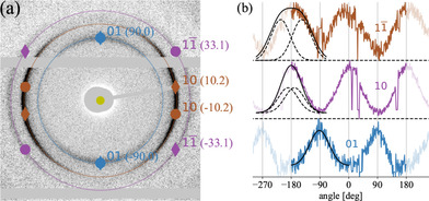
Figure 4.

(a) Expected scattering pattern for oblique lattice (parameters given in text) for the main reflections on top of measured difference pattern from Figure 2c. The angular position for each reflection is given in parenthesis (degrees). Circles represent reflections from the lattice shown in Figure 3a while diamonds represent reflections from the mirrored unitcell. (b) Angular intensities along reflection rings. Solid black lines are a Gaussian fit for 01 and the sum of two identical Gaussians with angular separation (dashed lines) for and 20. Note that the angular range is periodically expanded for better visualization.
