

Abstract
Chirality plays a major role in nature, from particle physics to DNA, and its control is much sought-after due to the scientific and technological opportunities it unlocks. For magnetic materials, chiral interactions between spins promote the formation of sophisticated swirling magnetic states such as skyrmions, with rich topological properties and great potential for future technologies. Currently, chiral magnetism requires either a restricted group of natural materials or synthetic thin-film systems that exploit interfacial effects. Here, using state-of-the-art nanofabrication and magnetic X-ray microscopy, we demonstrate the imprinting of complex chiral spin states via three-dimensional geometric effects at the nanoscale. By balancing dipolar and exchange interactions in an artificial ferromagnetic double-helix nanostructure, we create magnetic domains and domain walls with a well-defined spin chirality, determined solely by the chiral geometry. We further demonstrate the ability to create confined 3D spin textures and topological defects by locally interfacing geometries of opposite chirality. The ability to create chiral spin textures via 3D nanopatterning alone enables exquisite control over the properties and location of complex topological magnetic states, of great importance for the development of future metamaterials and devices in which chirality provides enhanced functionality.
Keywords: 3D, nanoprinting, nanomagnetic, chirality, topological, double-helix, X-ray
Chirality, or “handedness”, refers to the property characterizing three-dimensional structures that cannot be superimposed on their mirror image, as defined by Kelvin,1 Larmor,2 and Eddington.3 In nature, chirality is critical in determining a material’s functionality, from the chirality of molecules4 dictating key differences in properties such as flavor, toxicity, or drug effectiveness, to the catalysis of important biological reactions that played a role in the origin of life.5 Chirality generally requires three-dimensional systems and until recently was observed mostly in naturally occurring materials. With significant developments in nanofabrication, it has recently become possible to design chirality in metamaterials and devices. In particular, by patterning materials at the micro- and nanoscales in chiral geometries, broadband optical polarizers,6 microrobots,7 and sensors8 have been demonstrated.
In magnetism, chirality plays a critical role in the stabilization of chiral domain walls9 and spin spirals,10 as well as in the creation of topological spin textures such as skyrmions,11,12 antiskyrmions,13 and bobbers,14 which are very attractive for future nonvolatile computing technologies.15 In recent years, the antisymmetric exchange Dzyaloshinskii–Moriya interaction (DMI),16,17 describing chiral spin coupling, has been achieved either in certain non-centrosymmetric bulk crystals11,12 or through the careful design of high quality layered thin films and interfaces,18−20 leading to a fascinating array of magnetic effects.21−24
An alternative route to achieve magnetochirality is through 3D patterning. Relying solely on shape, geometric magnetochirality eliminates the stringent material requirements associated with bulk and interfacial DMI. In this realm, single-domain chiral magnetic metamaterials have been realized,25 and a range of magnetochiral effects have been predicted for inversion symmetry-breaking curved nanostructures,26−28 with recent experiments revealing geometric DMI to be of comparable magnitude to interfacial DMI29 and concepts existing to couple them to other physical effects such as magnetoelectricity.30
Results and Discussion
Design and Fabrication
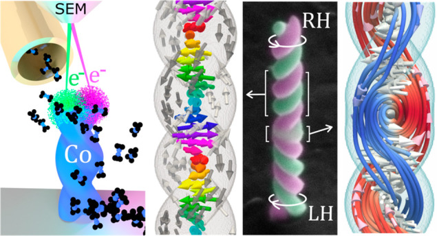
Via the combination of advanced 3D nanofabrication and magnetic microscopy, we reveal a rich and sophisticated collection of magnetic states reachable by purely 3D geometric means, ranging from helical domains to chiral spin textures and localized topological defects. As a prototypical system, we have designed a magnetic double-helix formed of two twisted and overlapping cylindrical nanowires (Figure 1). The double helix combines dipolar (Figure 1a) and exchange (Figure 1b) coupling with geometrically induced chirality (Figure 1c), giving rise to a rich magnetic energy landscape.
Figure 1.

Artificial double-helix nanomagnets. (a–c) Competing magnetic interactions in an artificial double-helix. Colors separate different regions of the system (two strands in green and magenta and core in yellow), with no difference in material composition. Arrow insets indicate spin alignment inside the dashed boxes. (a) Dipolar stray field minimization promotes an antiparallel state between strands. (b) Exchange coupling in the overlap region (yellow) favors the parallel alignment of spins. (c) Geometric chirality favors a given sense of spin rotation in a strand via shape anisotropy. (d) 3D-printing of a cobalt nanohelix by FEBID. After injection of Co2(CO)8 into the chamber of a scanning electron microscope (SEM) using a gas injection system (GIS), the focused electron beam (in green and magenta) alternatively exposes the two helix strands. (e) Colored SEM image of the nanostructure under investigation, consisting of two double-helices of opposite chirality joined at the tendril perversion marked with *. Scale bar 250 nm, image tilt 45°.
To experimentally realize this system, we have 3D-printed cobalt double-helix nanomagnets using focused electron beam induced deposition (FEBID), as illustrated in Figure 1d. The outstanding performance of FEBID for the direct-writing of ferromagnetic materials31,32 is exploited here to not only create double-helices with a single chirality but also combine two of them with opposite chirality (Figure 1e): left-handed (LH) and right-handed (RH) in the lower and upper parts, respectively. These two regions of opposite geometric chirality are interfaced via a structural defect, a nanometric tendril perversion33 (see * in Figure 1e). Each of the two nanowires forming the double-helix strands has a total length of 880 nm and a diameter of 85 nm, favoring an axial magnetic domain configuration due to shape anisotropy.34 Transmission electron microscopy (TEM) measurements reveal a geometrical overlap of 18 nm between the two strands, resulting in strong interstrand ferromagnetic exchange coupling. Further details are available in Methods.
Characterization of Stable Spin Textures
In order to identify the magnetic structure emerging in these systems, a high spatial resolution magnetic imaging technique is required.25,35−38 Here, we use full-field magnetic soft X-ray transmission microscopy39−41 (Figure 2a), exploiting X-ray magnetic circular dichroism (XMCD) at the cobalt L3 absorption edge. Using this technique, it is possible to infer the projection of magnetic moments parallel to the X-ray beam (x-direction in Figure 2a), by comparing two calibrated images taken with different X-ray polarization. More details are available in Methods.
Figure 2.

Geometric imprinting of magnetic chirality. (a) Schematic setup for synchrotron X-ray magnetic microscopy. X-rays are focused by a capillary condenser onto the sample. A magnified image is formed on a CCD by a Fresnel Zone plate. Two exposures with different polarization (selected by a slit) are taken to extract X-ray magnetic circular dichroism (XMCD) contrast, which is proportional to the x component of the nanostructure’s magnetization. (b) XMCD image of the double-helix studied, which changes geometric chirality at the *. Image at zero field, after application of a saturating field along −z. (c, d) Micromagnetic simulations of a RH (top) and LH (bottom) double-helix, after application of a saturating external field along −z. (c) Magnetic state for strands and core. (d) Computed XMCD signal from simulations in panel c. (e) XMCD image of the double-helix under study in the as-grown state. (f–h) Micromagnetic simulations for a RH (top) and LH (bottom) double helix with antiparallel magnetic alignment of the strands. (f) Internal spin structure for strands and core. (g) Corresponding calculated XMCD contrast. (h) Selected xy cross sections at different heights, revealing a chiral interstrand Bloch domain wall. (i) Volumetric representation of the 3D spin configuration of a single LH double helix with antiparallel magnetic alignment of the strands (gray arrows) and a helical Bloch domain wall in the core (color arrows). Scale bars in panels b and e, 200 nm.
We image the magnetic state of the sample in two different remanent states: after applying an axial (>0.5 T) magnetic field (Figure 2b–d) and the as-grown magnetic configuration (Figure 2e–i). After the application of the axial magnetic field (Figure 2b), a mirrored XMCD contrast is observed for the regions with opposite geometric chirality of the double helix: In the LH bottom part of the structure, the left-hand side has a positive (red) XMCD signal, contrary to the right-hand side, where it is negative (blue). This indicates that the projection of the magnetization along the x direction reverses when moving from the left to the right side of the structure. The opposite XMCD contrast is observed for the RH upper section of the helix. This pattern is consistent with the two intertwined helices being longitudinally magnetized in the direction of the applied field (parallel strand configuration). Due to the overlap between strands, the resulting magnetic configuration and XMCD contrast resembles a vortex state, as for example, in cylindrical nanowires of large diameter (see also Figure M11 in Supporting Information).42 Importantly, the magnetic circulation is opposite for LH and RH regions, that is, it is dependent on the geometric chirality (see also Figure M8 in Supporting Information).
To elucidate details of this magnetic configuration, we have performed micromagnetic simulations43 at remanence, after a saturating field along the helix axis (Figure 2c). The state is characterized by a shell of helical spins following the strand axes, due to dominant magnetic shape anisotropy. This results in the imprinting of magnetic LH (RH) helical domains at the bottom (top) parts of the structure, with a magnetic core parallel to the applied magnetic field (−z direction). The corresponding XMCD image calculated from the micromagnetic state is shown in Figure 2d, where the key feature observed in experiments, that is, the reversal of blue–red contrast for a change in geometric chirality, is reproduced. This result demonstrates the ability to directly imprint magnetic chiral states by exploiting the shape of an artificial helical nanomagnet.
We now explore the as grown magnetic state of the double-helix, revealing a rich magnetic configuration. The experimental XMCD image (Figure 2e) consists of a longitudinally alternating contrast, that appears independent of the geometric handedness (either LH or RH) of the double-helix. This alternating magnetic contrast is consistent with an antiparallel magnetic alignment of the strands, as the micromagnetic simulations (Figures 2f) and computed XMCD contrast (Figure 2g) elucidate. Small distortions in the experimental projection with respect to the simulated signal are well reproduced by considering the effect of small changes in illumination angles between both polarizations (see Methods). Simulations also indicate that the antiparallel strand alignment experimentally observed forms the ground state of the system. This state is expected to be formed during growth due to the high dipolar coupling between strands (Figure 1a), which favors the opposite mz magnetic configuration of the two strands (see Methods).
An intriguing magnetic structure becomes apparent when we consider the internal spin arrangement of this antiparallel magnetic state, as a closer look at the micromagnetic configuration reveals. Due to the existence of antiparallel magnetic domains for the two strands, a domain-wall at the core of the double-helix must form (see core spins in Figure 2f and in Figure 2i for greater detail). The presence of a wall is not directly visible in the X-ray data due to distortion caused by sample tilt but is a requirement due to the overlap of the strands (see TEM characterization in Methods) and an antiparallel magnetic state. Considering the spin evolution of the wall from bottom to top, a helical pattern is formed, with an opposite helicity for the LH (bottom) and RH (top) regions (Figure 2f). The chirality of this 3D spin wall is fully determined by the geometric chirality of each part of the structure. Moreover, if we examine the sense of rotation of the magnetization during the transition between strands (see cross sections along the xy plane in Figure 2h), this takes place via a Bloch domain wall with a well-defined chirality. This Bloch wall chirality is fundamentally determined by the nonzero angle formed between the strands, being thus opposite for top and bottom parts of the structure. This result constitutes a striking manifestation of the imprinting of geometric chirality into the magnetic texture of the double-helix.
Controlled Interfacing of Chiral Spin Textures
We have demonstrated how the sophisticated patterning of a symmetry-breaking 3D nanogeometry translates into a powerful spatial control of magnetic chirality. In the following, we study in more detail the type of 3D spin state that emerges when two regions with opposite magnetic chirality are forced to interact at the interchiral interface (*). Specifically, we focus on the antiparallel strand configuration, for which two helical Bloch walls of opposite chirality meet at (*) in Figure 3. To determine the 3D magnetic texture present at this chirality interface, the double-helix is rotated around its axis, as shown schematically in Figure 3a, and XMCD projections are measured at different rotation angles. An electronic contrast X-ray transmission image is shown in Figure 3b, where each half pitch of the double-helix is identified I to IX, with the perversion at turn IV*. Figure 3c,d corresponds to the experimental and simulated XMCD images at different angles, respectively. We first note that the XMCD contrast pattern shifts upward (downward) for the RH (LH) helix by half a period upon rotation by 90°, similarly to a barber pole. This confirms the antiparallel magnetic configuration. A significant change in the magnetic contrast is additionally observed at the chirality interface (*) during rotation, changing smoothly from a blue dot at 0° to a split contrast with red above and blue below * for the highest angles probed. This magnetic contrast evolution is reminiscent of the one corresponding to a magnetic vortex: for a vortex, in the perpendicular geometry the core is probed, which is seen as a bright or dark point, and as the sample is rotated into the in-plane geometry, the planar magnetic domains are probed, which exhibit opposite XMCD contrast at either side of the core. Micromagnetic simulations of the perversion (Figure 3e) reveal that indeed, a 3D vortex-like spin structure is stable at the perversion, and results in XMCD projections (Figure 3d) that match well the experimentally observed contrast (Figure 3c).
Figure 3.

Localized 3D spin texture and topological defect in a chirality interface. (a) Schematics of the experimental procedure by which the double-helix is rotated to measure X-ray magnetic images at different angles. (b) Reference electronic-contrast X-ray transmission image. Each double-helix half-pitch is marked from I to IX (tendril perversion located at IV*). (c) XMCD measurements taken at several rotation angles. A vortex-like spin state is identified from the angular evolution of the magnetic contrast in region *. (d) Simulated XMCD contrast for the spin structure in panel e, reproducing the magnetic pattern experimentally observed upon rotation. (e) Micromagnetic simulations of the linkage between two double-helices of opposite chirality with antiparallel magnetic alignment of their strands (blue and red arrows). LH (bottom) and RH (top) Bloch domain walls are present in the core (white arrows), and an asymmetric 3D vortex state emerges at the tendril perversion *. Represented viewpoint corresponds to 0° measurements. (f) Subset of spins in panel e after untwisting the magnetization state. Line cross sections are taken between the centers of the two helix strands at different heights and rotated into the xy plane revealing that the change in magnetic chirality (transition from a RH to a LH Bloch wall) takes place via the formation of an asymmetric vortex (gray area). The Néel-type defect mediating opposite chiralities (i), the vortex core (ii), and the deformed Bloch-wall (iii) discussed in the main text are indicated. Scale bar in panel c, 200 nm.
The micromagnetic configuration of the 3D vortex-like spin state can be further understood by untwisting the helical Bloch domain wall into a plane, as shown in Figure 3f. This procedure reveals that when two Bloch domain walls of opposite chirality meet at the perversion, an inversion of magnetic chirality occurs via the transformation of the Bloch walls to an intermediate Néel wall, indicated by (i) in Figure 3f. The emergence of this topological defect is analogous to the formation of Bloch lines in materials hosting magnetic bubbles, where a line with Néel character arises to mediate a chirality transition between opposite-chirality Bloch domain walls.15 Here, the presence of this Néel defect generates a circulation in the magnetization around a central core (ii), as detected experimentally. We note that it is the Néel defect in (i), and not the circulation of the magnetization vector field, that constitutes a topological defect. The resulting spin configuration, however, is not equivalent to a traditional vortex found in planar systems, where a symmetric circulation with respect to the vortex core would take place. An asymmetric 3D vortex state arises instead, characterized by the deformation of the LH Bloch domain wall below the core (iii), an effect promoted by the geometry and dimensions of the perversion, in combination with the twisting of the interconnected strands. The experimentally observed RH vortex chirality implies that this defect is located above the vortex core. This observation is consistent with the location of the Néel defect being determined by flux closure during nanostructure growth (see Topological Control section). Based on this effect, by inverting the order of growth, an asymmetric vortex of opposite chirality could be deterministically created at the tendril perversion. Additionally, as well as the asymmetric vortex with RH chirality observed experimentally at the perversion, micromagnetic simulations reveal that other states such as a Bloch point wall may also be stable (Methods) and could potentially be accessed via demagnetization protocols or thermal activation. These results establish the interchirality boundary as a powerful platform for the formation of complex 3D magnetic states.
Conclusion
This work demonstrates powerful spatial control over spin chiral properties via purely three-dimensional geometric nanoscale effects. By a careful design of the geometry of a three-dimensional chiral nanomagnet, patterned via advanced direct-write lithography, we are able to imprint sophisticated chiral spin states. We control the helicity and location of magnetic domains and domain walls and the internal chirality of domain walls interfacing helical domains. We also show how via the introduction of structural defects mediating opposite magnetochiral regions, localized 3D spin textures and topological defects can be realized. The platform shown here represents an exciting route to study three-dimensional chiral spin systems, discover unknown spin textures,44,45 and develop future magnetic nanodevices.46
Methods
3D Nanoprinting
The double-helix has been fabricated using focused electron beam induced deposition (FEBID) in a Thermo Fischer Scientific Xenon-Plasma FIB Helios 650, at the Kelvin Nanocharacterisation Centre of the University of Glasgow, UK. Co2(CO)8 is used as the precursor gas. In this technique, the precursor gas is locally decomposed into Co using the focused beam of electrons from a scanning electron microscope (SEM). Metallic purities between 70% and 90% for the conditions employed are typically reached.47 To produce a magnetic double-helix with controlled structural chirality, the electron beam is computer-controlled to alternatively expose two spots (green and magenta in Figure 1e), that rotate as the nanostructure grows. The parameters listed in Table M1 of the Supporting Information were employed.
The nanoprinting process is performed by programming a beam-scanning pattern using a text file. The text file is available as part of the supplementary data set; it programs a beam displacement as described in Figure M1a,b. The beam is programmed to move alternatively on the SEM focal plane, between two spots that rotate first clockwise and then anticlockwise. The coordinates of the two spots are represented in red and black, respectively, in Figure M1a,b The dwell time (time that the beam spends in one spot) is given in Figure M1c and is increased as the structure grows to empirically correct thermal-related effects that reduce growth rate as the nanostructure becomes taller.31 An intermediate region where the beam is rotated at a fast speed is introduced to create the tendril perversion (*) between the two double-helix structures. The nanostructure resulting from this exposure is shown in Figure M1d.
Geometrical Characterization
Detailed geometrical characterization of the double-helices was performed using scanning electron microscopy (SEM) and transmission electron microscopy (TEM). From this series of images, we confirm that a negligible phase difference between the two strands exists, with top and bottom parts of the same strand reaching the joint at points of the same (x,y) value. Figure M2 presents a set of SEM orbits taken to confirm the accuracy of the fabrication process.
The strand diameter and separation have been determined by transmission electron microscopy (TEM) via line profiles (Figure M3a–c) extracted using ImageJ.48,49 A strand diameter of 85 ± 5 nm and a total width for the double helix of 150 ± 5 nm are obtained. This corresponds to a separation between strands (center-to-center distance) of 68 ± 5 nm and an overlap of 18 ± 5 nm.
TEM measurements to determine the helix pitch and total length are presented in Figure M3d,e, finding a pitch of 290 ± 20 nm/turn at the top of the structure and 250 ± 20 nm/turn at the base. The total structure length is measured to be 1350 ± 100 nm. The total length of each of the 4 twisting nanowires forming the arms of the two double-helices of opposite chirality is estimated to be 880 nm based on the length of a spiral curve with a pitch of 250 and 68 nm diameter. The size of the tendril perversion along the z-direction is estimated to be 50 ± 10 nm, based on TEM characterization at three angles of rotation (see Figure M4).
Magnetic X-ray Imaging
Full-field soft X-ray magnetic microscopy experiments have been performed at the MISTRAL beamline of the ALBA synchrotron.39 The operating energy of the microscope is selected at 0.4 eV below the cobalt L3 peak, a compromise between excessive absorption and strong X-ray magnetic circular dichroism (XMCD) contrast. The spectrum used for energy calibration is shown in Figure M5. In this study, we employ two slit positions, denoted UP and MID, which correspond to regions of the X-ray emission cone above the storage ring (UP) and in the plane of the storage ring (MID), as displayed in Figure M5b. This choice simplifies data analysis since one of the images (MID position) only contains geometrical information. The beamline calibration protocol and reference samples employed are described in more detail in Protocol 1 of the Supporting Information.
Micromagnetic Simulations
Two sets of micromagnetic
simulations are performed in this work. The first one consists of
the evaluation of different magnetic states that double-helix structures
can host and their stability at zero fields. The second one consists
of studying the type of spin structures emerging at the tendril perversion
in our structures. XMCD contrast associated with the different magnetic
configurations is computed in all cases. The simulations are performed
employing the finite-difference package Mumax3 (ref (43)), using a Nvidia GTX1080Ti
graphical processing unit. FEBID cobalt is modeled using a saturation
magnetization Ms = 9 × 10⁵ A/m and exchange stiffness Aex = 10–11 J/m. No magnetocrystalline anisotropy is included,
due to the nanocrystalline nature of FEBID cobalt.50 A cubic mesh with size of 2.5 nm is employed. The dipolar
exchange length of this simulated material is  . The simulated structure
dimensions are
based on TEM measurements (see above): length = 750 nm, strand diameter
= 86 nm, center-to-center strand distance = 66 nm, and pitch = 240
nm/turn. Tendril perversion length = 50 nm.
. The simulated structure
dimensions are
based on TEM measurements (see above): length = 750 nm, strand diameter
= 86 nm, center-to-center strand distance = 66 nm, and pitch = 240
nm/turn. Tendril perversion length = 50 nm.
First, we investigate the different magnetic states that can be stable in a LH double helix, using a numerical annealing protocol. For this, the magnetic configuration is initialized in three possible ways: random, longitudinally uniform and transversely uniform. After initialization, a random field of decreasing amplitude is applied 21 times to help the system escape from artificial grid-pinning, using the temperature module of the Mumax3 software.51 The temperatures applied and the length of time they were applied are shown in Figure M8a, where each dot represents a simulation step. A steepest gradient descent (SGD, see magenta dots) is performed at the end of each thermal cycle to evaluate the final energy of the system as closely as possible to the local minimum. The first red dot corresponds to the initialization of the system, and the spin configuration is saved after each SGD minimization. For each initialization state, the 21-step cycle is repeated 50 times to gather statistics. The resulting 3150 magnetic states (3 initializations × 21 thermal cycles × 50 repetitions) are then clustered using exchange and demagnetizing energy, to evaluate what final states result from each initialization process. We find that a longitudinally uniform initialization (Figure M8b,c) leads preferably to LH magnetization states, which coincide with the geometric chirality of the simulated double-helix. In contrast, both transversely uniform (Figure M8d,e) and random (not shown here) initializations mostly lead to an antiparallel strand configuration, which is the stable remanent state observed in simulations with the lowest total energy. These findings agree with the experimental observations presented in the main text.
Second, we have investigated what possible micromagnetic spin configurations are stable in a tendril perversion, in the case of an antiparallel strand alignment. For this, we initialize the strands with an antiparallel state, and the tendril perversion volume interfacing the two sets of double helices with a random magnetic configuration. The system is then driven to a local minimum at zero magnetic field, using a steepest gradient descent, just after 2 ns of time evolution at a temperature of 2000 K. This intermediate computational step avoids diverging solutions of the steepest gradient engine due to the random initialization. Following this procedure for all possible combinations of arm initializations, we have observed three different stable states mediating Bloch domain walls of different chirality, as illustrated in Figure M9: an asymmetric 3D vortex as described in the main text, a magnetic configuration hosting a Bloch-point, and an “oblique” 3D vortex state.
The XMCD contrast is then calculated from simulations by numerically integrating m⃗·x̂ along x̂ (the direction of X-ray propagation in experiments), for different nanostructure axial rotations (see Figure 3a). Figure M10a–c shows the computed XMCD projections for each of the three stable spin textures obtained in simulations, for a full 360° rotation in steps of 15°. Clear distinct features are observed for each state upon rotation, which allows us to conclude that an asymmetric 3D vortex is present in the tendril perversion in the as grown state experimentally investigated.
Finally, the distortion observed in experimental XMCD images for an antiparallel alignment between strands (see Figure 2e) has been modeled by numerically integrating the total transmitted intensity through a double-helix with this magnetic state, according to
using μ = 3.2 × 10⁷ m–1 and δ = μ/3 or 0, depending on whether the X-rays are polarized.
The distortion observed in the XMCD images is consistent with an experiment where the imaging process takes place under two different X-ray incident angles, depending on X-ray polarization (4° difference assumed), and a tilted 3D magnetic nanostructure. To reproduce the distortion in simulations, two XMCD images are computed using two different tilts (15° and 19°) with respect to the direction of the virtual incident X-rays. The two resulting absorption images are then aligned using the same difference-minimization protocol employed with experimental data. Figure M10d shows the experimental XMCD signal of a selected area of the double helix (left) and the simulated image result of this procedure (right). A good agreement between both is obtained, confirming that the tilting of the free-standing 3D nanostructure during the imaging process is the most likely reason behind this effect.
Topological Control
The experimentally observed RH chirality for the asymmetric vortex at the tendril perversion * and the micromagnetic analysis connected to Figure M10d strongly suggest that the chirality of the vortex spin texture and the position of the Néel defect is determined by the order in which the double-helix structures were grown due to magnetic flux closure during the growth process. This is illustrated in Figure M12 in the Supporting Information.
This figure is a schematic representation of the untwisted magnetization state at different steps of the growth, the most energetically favorable antiparallel strand alignment is considered.
In panels a–d, the different steps of the growth process are illustrated for the case studied in the manuscript (i.e., a LH double-helix is grown first, followed by a RH double-helix). The growth starts with a LH magnetic Bloch inside the first double helix (black arrows in panel b), favored by geometrical chirality.
Next, when the tendril perversion is grown (panel c), magnetic flux closure favors a magnetic cap with a clockwise rotation of the magnetization around the domain wall (yellow region). This direction of flux closure, in combination with the LH chirality of the Bloch wall in the double-helix, fixes the chirality of the circulation of the asymmetric vortex that will form next.
When the RH double-helix is added on top (panel d), a RH Bloch wall is strongly favored inside the gray area, due to its chiral geometry. As a consequence of the chirality mismatch between the yellow and gray regions, a Néel defect (green region) is topologically required.
The dotted arrow below the vortex core at the yellow region represents a circulation of the magnetization consequence of the clockwise rotation of magnetic flux generated by the Néel defect. This circulation does not constitute a topological defect, as it can be continuously deformed into a LH Bloch wall connecting the vortex core and the bottom Bloch wall, since the orientation of the vortex core and the LH Bloch wall below the vortex are the same. As a consequence of this magnetic state, an asymmetric 3D vortex is formed.
Based on this reasoning, if the growth occurred in the opposite order, with the RH helix grown first instead, the chirality of the asymmetric vortex would have been reversed, as illustrated in panels e–h of the figure. This provides an interesting future perspective for the controlled generation of complex spin textures. Determining the exact relation between the growth details and the presence of other stable textures (Bloch-point, oblique 3D vortex) or whether these configurations could be accessed by, for example, demagnetization protocols is beyond the scope of this work and is left for future studies.
Acknowledgments
This work was funded by EPSRC Early Career Fellowship EP/M008517/1, the Winton Program for the Physics of Sustainability, and the EU CELINA COST action. D.S.-H. acknowledges a Girton College Pfeiffer scholarship and support from the EPSRC CDT in Nanoscience and Nanotechnology. A.H.-R. and S.M.V. acknowledge funding from the EU Horizon 2020 program through Marie Skłodowska-Curie Action H2020-MSCA-IF-2016-74695. C.D. acknowledges funding from Leverhulme Trust (ECF-2018-016), Isaac Newton Trust (18-08), and a L’Oréal-UNESCO UK and Ireland Fellowship for Women in Science 2019. Funding by the Spanish Ministry of Science is acknowledged, grants MAT2017-82970-C2-1-R, MAT2017-82970-C2-2-R and MAT2018-102627-T, and by Aragon Government (Construyendo Europa desde Aragón), grant E13_20R including European Social Fund. J.P.-N. acknowledges MINECO funding BES-2015-072950. S.M.V. appreciates support from EPSRC EP/M024423/1. P.F. was supported by the U.S. Department of Energy, Office of Science, Office of Basic Energy Sciences, Materials Sciences and Engineering Division, Contract No. DE-AC02-05-CH11231 (NEMM program MSMAG). These experiments were performed at MISTRAL beamline at ALBA Synchrotron with the collaboration of ALBA staff and CALIPSOplus (Grant 730872) funding. We thank R. Streubel, M-Y. Im, and M. Sanz-Hernández for stimulating discussions. We acknowledge W. Smith, C. How, and S. McFadzean for electron microscopy technical support and R. Valcarcel for X-ray microscopy technical support.
Supporting Information Available
The Supporting Information is available free of charge at https://pubs.acs.org/doi/10.1021/acsnano.0c00720.
Author Contributions
D.S.-H. and A.F.-P. designed the experiments. D.S.-H. and A.H.-R. fabricated the samples. D.S.-H. performed micromagnetic simulations. D.S.-H., A.H.-R., C.D., A.S., J.P.-N., S.F., P.F., and A.F.-P. performed X-ray microscopy experiments. D.S.-H. developed X-ray measurement protocols with the help of C.D., A.H.-R. and A.F.-P. D.S.-H., C.D., and A.H.-R. analyzed the X-ray data. E.P. built, maintained, and supervised the X-ray experiment. A.H.-R. performed TEM measurements. D.S.-H., A.H.-R., C.D., and A.F.-P. wrote the paper. D.S.-H. created the figures. All authors contributed to the interpretation and discussion of results.
The authors declare no competing financial interest.
Notes
Raw data, Mumax3 simulation scripts, and simulation results are available publicly at Enlighten, the data repository of the University of Glasgow (http://dx.doi.org/10.5525/gla.researchdata.1002). The code employed to calculate XMCD images from micromagnetic data is available from the corresponding authors upon reasonable request.
Supplementary Material
References
- Kelvin W. T. B.Baltimore Lectures on Molecular Dynamics and the Wave Theory of Light; C. J. Clay and Sons: London, 1904; p 619. [Google Scholar]
- Larmor J.Aether and Matter; C. J. Clay and Sons: London, 1900; p 142. [Google Scholar]
- Eddington A.Fundamental Theory; Cambridge University Press: Cambridge, 1946; p 109. [Google Scholar]
- Bentley R. The Nose as a Stereochemist. Enantiomers and Odor. Chem. Rev. 2006, 106, 4099–4112. 10.1021/cr050049t. [DOI] [PubMed] [Google Scholar]
- Hazen R. M.; Sholl D. S. Chiral Selection on Inorganic Crystalline Surfaces. Nat. Mater. 2003, 2, 367–374. 10.1038/nmat879. [DOI] [PubMed] [Google Scholar]
- Gansel J. K.; Thiel M.; Rill M. S.; Decker M.; Bade K.; Saile V.; von Freymann G.; Linden S.; Wegener M. Gold Helix Photonic Metamaterial as Broadband Circular Polarizer. Science 2009, 325, 1513–1515. 10.1126/science.1177031. [DOI] [PubMed] [Google Scholar]
- Tottori S.; Zhang L.; Qiu F.; Krawczyk K. K.; Franco-Obregón A.; Nelson B. J. Magnetic Helical Micromachines: Fabrication, Controlled Swimming, and Cargo Transport. Adv. Mater. 2012, 24, 811–816. 10.1002/adma.201103818. [DOI] [PubMed] [Google Scholar]
- Wu Z.; Chen X.; Wang M.; Dong J.; Zheng Y. High-Performance Ultrathin Active Chiral Metamaterials. ACS Nano 2018, 12, 5030–5041. 10.1021/acsnano.8b02566. [DOI] [PubMed] [Google Scholar]
- Parkin S.; Yang S.-H. Memory on the Racetrack. Nat. Nanotechnol. 2015, 10, 195–198. 10.1038/nnano.2015.41. [DOI] [PubMed] [Google Scholar]
- Legrand W.; Maccariello D.; Ajejas F.; Collin S.; Vecchiola A.; Bouzehouane K.; Reyren N.; Cros V.; Fert A. Room-Temperature Stabilization of Antiferromagnetic Skyrmions in Synthetic Antiferromagnets. Nat. Mater. 2020, 19, 34. 10.1038/s41563-019-0468-3. [DOI] [PubMed] [Google Scholar]
- Muhlbauer S.; Binz B.; Jonietz F.; Pfleiderer C.; Rosch A.; Neubauer A.; Georgii R.; Boni P. Skyrmion Lattice in a Chiral Magnet. Science (Washington, DC, U. S.) 2009, 323, 915–919. 10.1126/science.1166767. [DOI] [PubMed] [Google Scholar]
- Neubauer A.; Pfleiderer C.; Binz B.; Rosch A.; Ritz R.; Niklowitz P. G.; Böni P. Topological Hall Effect in the A Phase of MnSi. Phys. Rev. Lett. 2009, 102, 186602. 10.1103/PhysRevLett.102.186602. [DOI] [PubMed] [Google Scholar]
- Nayak A. K.; Kumar V.; Ma T.; Werner P.; Pippel E.; Sahoo R.; Damay F.; Rößler U. K.; Felser C.; Parkin S. S. P. Magnetic Antiskyrmions above Room Temperature in Tetragonal Heusler Materials. Nature 2017, 548, 561–566. 10.1038/nature23466. [DOI] [PubMed] [Google Scholar]
- Zheng F.; Rybakov F. N.; Borisov A. B.; Song D.; Wang S.; Li Z.-A.; Du H.; Kiselev N. S.; Caron J.; Kovács A.; Tian M.; Zhang Y.; Blügel S.; Dunin-Borkowski R. E. Experimental Observation of Chiral Magnetic Bobbers in B20-Type FeGe. Nat. Nanotechnol. 2018, 13, 451–455. 10.1038/s41565-018-0093-3. [DOI] [PubMed] [Google Scholar]
- Fert A.; Cros V.; Sampaio J. Skyrmions on the Track. Nat. Nanotechnol. 2013, 8, 152–156. 10.1038/nnano.2013.29. [DOI] [PubMed] [Google Scholar]
- Dzyaloshinsky I. A Thermodynamic Theory of “Weak” Ferromagnetism of Antiferromagnetics. J. Phys. Chem. Solids 1958, 4, 241–255. 10.1016/0022-3697(58)90076-3. [DOI] [Google Scholar]
- Moriya T. Anisotropic Superexchange Interaction and Weak Ferromagnetism. Phys. Rev. 1960, 120, 91–98. 10.1103/PhysRev.120.91. [DOI] [Google Scholar]
- Moreau-Luchaire C.; Moutafis C.; Reyren N.; Sampaio J.; Vaz C. A. F.; Van Horne N.; Bouzehouane K.; Garcia K.; Deranlot C.; Warnicke P.; Wohlhüter P.; George J.-M.; Weigand M.; Raabe J.; Cros V.; Fert A. Additive Interfacial Chiral Interaction in Multilayers for Stabilization of Small Individual Skyrmions at Room Temperature. Nat. Nanotechnol. 2016, 11, 444–448. 10.1038/nnano.2015.313. [DOI] [PubMed] [Google Scholar]
- Woo S.; Litzius K.; Krüger B.; Im M.-Y.; Caretta L.; Richter K.; Mann M.; Krone A.; Reeve R. M.; Weigand M.; Agrawal P.; Lemesh I.; Mawass M.-A.; Fischer P.; Kläui M.; Beach G. S. D. Observation of Room-Temperature Magnetic Skyrmions and Their Current-Driven Dynamics in Ultrathin Metallic Ferromagnets. Nat. Mater. 2016, 15, 501–506. 10.1038/nmat4593. [DOI] [PubMed] [Google Scholar]
- Fernández-Pacheco A.; Vedmedenko E.; Ummelen F.; Mansell R.; Petit D.; Cowburn R. P. Symmetry-Breaking Interlayer Dzyaloshinskii–Moriya Interactions in Synthetic Antiferromagnets. Nat. Mater. 2019, 18, 679–684. 10.1038/s41563-019-0386-4. [DOI] [PubMed] [Google Scholar]
- Schoenherr P.; Müller J.; Köhler L.; Rosch A.; Kanazawa N.; Tokura Y.; Garst M.; Meier D. Topological Domain Walls in Helimagnets. Nat. Phys. 2018, 14, 465–468. 10.1038/s41567-018-0056-5. [DOI] [Google Scholar]
- Litzius K.; Lemesh I.; Krüger B.; Bassirian P.; Caretta L.; Richter K.; Büttner F.; Sato K.; Tretiakov O. A.; Förster J.; Reeve R. M.; Weigand M.; Bykova I.; Stoll H.; Schütz G.; Beach G. S. D.; Kläui M. Skyrmion Hall Effect Revealed by Direct Time-Resolved X-Ray Microscopy. Nat. Phys. 2017, 13, 170–175. 10.1038/nphys4000. [DOI] [Google Scholar]
- Kurumaji T.; Nakajima T.; Hirschberger M.; Kikkawa A.; Yamasaki Y.; Sagayama H.; Nakao H.; Taguchi Y.; Arima T.-H.; Tokura Y. Skyrmion Lattice with a Giant Topological Hall Effect in a Frustrated Triangular-Lattice Magnet. Science 2019, 365, 914–918. 10.1126/science.aau0968. [DOI] [PubMed] [Google Scholar]
- Avci C. O.; Rosenberg E.; Caretta L.; Büttner F.; Mann M.; Marcus C.; Bono D.; Ross C. A.; Beach G. S. D. Interface-Driven Chiral Magnetism and Current-Driven Domain Walls in Insulating Magnetic Garnets. Nat. Nanotechnol. 2019, 14, 561–566. 10.1038/s41565-019-0421-2. [DOI] [PubMed] [Google Scholar]
- Phatak C.; Liu Y.; Gulsoy E. B.; Schmidt D.; Franke-Schubert E.; Petford-Long A. Visualization of the Magnetic Structure of Sculpted Three-Dimensional Cobalt Nanospirals. Nano Lett. 2014, 14, 759–764. 10.1021/nl404071u. [DOI] [PubMed] [Google Scholar]
- Volkov O. M.; Sheka D. D.; Gaididei Y.; Kravchuk V. P.; Rößler U. K.; Fassbender J.; Makarov D. Mesoscale Dzyaloshinskii-Moriya Interaction: Geometrical Tailoring of the Magnetochirality. Sci. Rep. 2018, 8, 866. 10.1038/s41598-017-18835-4. [DOI] [PMC free article] [PubMed] [Google Scholar]
- Streubel R.; Fischer P.; Kronast F.; Kravchuk V. P.; Sheka D. D.; Gaididei Y.; Schmidt O. G.; Makarov D. Magnetism in Curved Geometries. J. Phys. D: Appl. Phys. 2016, 49, 363001. 10.1088/0022-3727/49/36/363001. [DOI] [Google Scholar]
- Hertel R. Curvature-Induced Magnetochirality. SPIN 2013, 03, 1340009. 10.1142/S2010324713400092. [DOI] [Google Scholar]
- Volkov O. M.; Kákay A.; Kronast F.; Mönch I.; Mawass M.-A.; Fassbender J.; Makarov D. Experimental Observation of Exchange-Driven Chiral Effects in Curvilinear Magnetism. Phys. Rev. Lett. 2019, 123, 077201 10.1103/PhysRevLett.123.077201. [DOI] [PubMed] [Google Scholar]
- Volkov O. M.; Rößler U. K.; Fassbender J.; Makarov D. Concept of Artificial Magnetoelectric Materials via Geometrically Controlling Curvilinear Helimagnets. J. Phys. D: Appl. Phys. 2019, 52, 345001. 10.1088/1361-6463/ab2368. [DOI] [Google Scholar]
- Skoric L.; Sanz-Hernández D.; Meng F.; Donnelly C.; Merino-Aceituno S.; Fernández-Pacheco A. Layer-by-Layer Growth of Complex-Shaped Three-Dimensional Nanostructures with Focused Electron Beams. Nano Lett. 2020, 20, 184–191. 10.1021/acs.nanolett.9b03565. [DOI] [PubMed] [Google Scholar]
- De Teresa J. M.; Fernández-Pacheco A.; Córdoba R.; Serrano-Ramón L.; Sangiao S.; Ibarra M. R. Review of Magnetic Nanostructures Grown by Focused Electron Beam Induced Deposition (FEBID). J. Phys. D: Appl. Phys. 2016, 49, 243003. 10.1088/0022-3727/49/24/243003. [DOI] [Google Scholar]
- McMillen T.; Goriely A. Tendril Perversion in Intrinsically Curved Rods. J. Nonlinear Sci. 2002, 12, 241–281. 10.1007/s00332-002-0493-1. [DOI] [Google Scholar]
- Landeros P.; Suarez O. J.; Cuchillo A.; Vargas P. Equilibrium States and Vortex Domain Wall Nucleation in Ferromagnetic Nanotubes. Phys. Rev. B: Condens. Matter Mater. Phys. 2009, 79, 024404 10.1103/PhysRevB.79.024404. [DOI] [Google Scholar]
- Tanigaki T.; Takahashi Y.; Shimakura T.; Akashi T.; Tsuneta R.; Sugawara A.; Shindo D. Three-Dimensional Observation of Magnetic Vortex Cores in Stacked Ferromagnetic Discs. Nano Lett. 2015, 15, 1309–1314. 10.1021/nl504473a. [DOI] [PubMed] [Google Scholar]
- Donnelly C.; Guizar-Sicairos M.; Scagnoli V.; Gliga S.; Holler M.; Raabe J.; Heyderman L. J. Three-Dimensional Magnetization Structures Revealed with X-Ray Vector Nanotomography. Nature 2017, 547, 328–331. 10.1038/nature23006. [DOI] [PubMed] [Google Scholar]
- Hierro-Rodriguez A.; Quirós C.; Sorrentino A.; Alvarez-Prado L. M.; Martín J. I.; Alameda J. M.; McVitie S.; Pereiro E.; Vélez M.; Ferrer S.. Revealing 3D Magnetization of Thin Films with Soft X - Ray Tomography at Nanometer Resolution. arXiv, 2019, 1907.01261, http://arxiv.org/abs/1907.01261 (accessed October 27, 2019). [DOI] [PMC free article] [PubMed]
- Streubel R.; Kronast F.; Fischer P.; Parkinson D.; Schmidt O. G.; Makarov D. Retrieving Spin Textures on Curved Magnetic Thin Films with Full-Field Soft X-Ray Microscopies. Nat. Commun. 2015, 6, 7612. 10.1038/ncomms8612. [DOI] [PMC free article] [PubMed] [Google Scholar]
- Sorrentino A.; Nicolás J.; Valcárcel R.; Chichón F. J.; Rosanes M.; Avila J.; Tkachuk A.; Irwin J.; Ferrer S.; Pereiro E. IUCr. MISTRAL: A Transmission Soft X-Ray Microscopy Beamline for Cryo Nano-Tomography of Biological Samples and Magnetic Domains Imaging. J. J. Synchrotron Radiat. 2015, 22, 1112–1117. 10.1107/S1600577515008632. [DOI] [PubMed] [Google Scholar]
- Fischer P.; Eimüller T.; Schütz G.; Guttmann P.; Schmahl G.; Pruegl K.; Bayreuther G. Imaging of Magnetic Domains by Transmission X-Ray Microscopy. J. Phys. D: Appl. Phys. 1998, 31, 649–655. 10.1088/0022-3727/31/6/012. [DOI] [Google Scholar]
- Blanco-Roldán C.; Quirós C.; Sorrentino A.; Hierro-Rodríguez A.; Álvarez-Prado L. M.; Valcárcel R.; Duch M.; Torras N.; Esteve J.; Martín J. I.; Vélez M.; Alameda J. M.; Pereiro E.; Ferrer S. Nanoscale Imaging of Buried Topological Defects with Quantitative X-Ray Magnetic Microscopy. Nat. Commun. 2015, 6, 8196. 10.1038/ncomms9196. [DOI] [PMC free article] [PubMed] [Google Scholar]
- Staňo M.; Fruchart O. Magnetic Nanowires and Nanotubes. Handb. Magn. Mater. 2018, 27, 155–267. 10.1016/bs.hmm.2018.08.002. [DOI] [Google Scholar]
- Vansteenkiste A.; Leliaert J.; Dvornik M.; Helsen M.; Garcia-Sanchez F.; Van Waeyenberge B. The Design and Verification of MuMax3. AIP Adv. 2014, 4, 107133. 10.1063/1.4899186. [DOI] [Google Scholar]
- Sutcliffe P. Hopfions in Chiral Magnets. J. Phys. A: Math. Theor. 2018, 51, 375401. 10.1088/1751-8121/aad521. [DOI] [Google Scholar]
- Liu Y.; Lake R. K.; Zang J. Binding a Hopfion in a Chiral Magnet Nanodisk. Phys. Rev. B: Condens. Matter Mater. Phys. 2018, 98, 174437. 10.1103/PhysRevB.98.174437. [DOI] [Google Scholar]
- Fernández-Pacheco A.; Streubel R.; Fruchart O.; Hertel R.; Fischer P.; Cowburn R. P. Three-Dimensional Nanomagnetism. Nat. Commun. 2017, 8, 15756. 10.1038/ncomms15756. [DOI] [PMC free article] [PubMed] [Google Scholar]
- Pablo-Navarro J.; Sanz-Hernández D.; Magén C.; Fernández-Pacheco A.; de Teresa J. M. Tuning Shape, Composition and Magnetization of 3D Cobalt Nanowires Grown by Focused Electron Beam Induced Deposition (FEBID). J. Phys. D: Appl. Phys. 2017, 50, 18LT01. 10.1088/1361-6463/aa63b4. [DOI] [Google Scholar]
- Schindelin J.; Arganda-Carreras I.; Frise E.; Kaynig V.; Longair M.; Pietzsch T.; Preibisch S.; Rueden C.; Saalfeld S.; Schmid B.; Tinevez J.-Y.; White D. J.; Hartenstein V.; Eliceiri K.; Tomancak P.; Cardona A. Fiji: An Open-Source Platform for Biological-Image Analysis. Nat. Methods 2012, 9, 676–682. 10.1038/nmeth.2019. [DOI] [PMC free article] [PubMed] [Google Scholar]
- Schneider C. A.; Rasband W. S.; Eliceiri K. W. NIH Image to ImageJ: 25 Years of Image Analysis. Nat. Methods 2012, 9, 671–675. 10.1038/nmeth.2089. [DOI] [PMC free article] [PubMed] [Google Scholar]
- Fernandez-Pacheco A.; De Teresa J. M.; Szkudlarek A.; Córdoba R.; Ibarra M. R.; Petit D.; O’Brien L.; Zeng H. T.; Lewis E. R.; Read D. E.; Cowburn R. P. Magnetization Reversal in Individual Cobalt Micro-and Nanowires Grown by Focused-Electron-Beam-Induced-Deposition. Nanotechnology 2009, 20, 475704. 10.1088/0957-4484/20/47/475704. [DOI] [PubMed] [Google Scholar]
- Leliaert J.; Mulkers J.; De Clercq J.; Coene A.; Dvornik M.; Van Waeyenberge B. Adaptively Time Stepping the Stochastic Landau-Lifshitz-Gilbert Equation at Nonzero Temperature: Implementation and Validation in MuMax 3. AIP Adv. 2017, 7, 125010. 10.1063/1.5003957. [DOI] [Google Scholar]
Associated Data
This section collects any data citations, data availability statements, or supplementary materials included in this article.