

Abstract
With a certain amount of filtration efficiency with rated flow, the structural design of HEPA filter at present is how to obtain the minimum pressure drop with the corrugation angle (for the type with isolator), the corrugation height (for the type with isolator) or the line height (for the type without isolator), and the passage depth (for both types).
Keywords: Pressure Drop, Equivalent Diameter, Structural Resistance, Frictional Resistance, Optimal Depth
With a certain amount of filtration efficiency with rated flow, the structural design of HEPA filter at present is how to obtain the minimum pressure drop with the corrugation angle (for the type with isolator), the corrugation height (for the type with isolator) or the line height (for the type without isolator), and the passage depth (for both types).
Flow State in the Passage of HEPA Filter
For the flow state in the passage (inlet and outlet) of ideal HEPA filter with isolator as shown in Fig. 5.1, Cheng Daiyun obtained the calculation result about the flow distribution in the passage on the basis of Bernoulli equation and modified momentum conservation equation, which is shown in Fig. 5.2 and Table 5.1 [1].
Fig. 5.1.
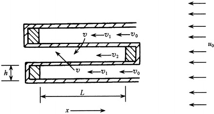
Model for passage of air filter
Fig. 5.2.

Relationship between the velocity and distance in the passage
Table 5.1.
Calculation result about the velocity distribution in passage of air filter with low initial velocity (m/s) and high corrugation (several millimeters)
| x/L | v 1/v 0 |
|---|---|
| 0.1 | 0.899 |
| 0.2 | 0.800 |
| 0.3 | 0.701 |
| 0.4 | 0.603 |
| 0.5 | 0.505 |
| 0.6 | 0.407 |
| 0.7 | 0.308 |
| 0.8 | 0.207 |
| 0.9 | 0.105 |
The conclusion obtained is that under the condition of low initial velocity, high corrugation, and high pressure drop, the flow in the passage is close to laminar flow with linear distribution of velocity (Re < 2,000), i.e.,
 |
5.1 |
 |
5.2 |
Otherwise, the nonlinear distribution will be obvious.
Experiment with Laser Doppler velocimeter has proved the above conclusion, which is shown in Fig. 5.3 [1]. In terms of outlet passage, the linear correlation coefficient of velocity distribution is more than 0.99.
Fig. 5.3.

Measured axial distribution of velocity along the outlet passage
Total Pressure Drop of HEPA Filter
According to 10.1007/978-3-642-39374-7_4, the total pressure drop of air filter can be expressed as:
 |
5.3 |
where
ΔP 1 is the pressure drop of filter media;
ΔP 2(1) is the frictional resistance of inlet passage;
ΔP 2(2) is the frictional resistance of outlet passage;
C is the local resistance of both inlet and outlet passages;
ΔP 3 is the local resistance of inlet passage;
ΔP 4 is the local resistance of outlet passage.
The core purpose of structural design is to calculate the pressure drop. Foreign scholar has proposed other kind of the expression for the total pressure drop [2]. It did not reflect the influence of the flow rate, so the meaning is not clear. But in 10.1007/978-3-642-39374-7_4 we know that ΔP 2 is related to the n power of the velocity, where the exponent n should be determined by experiment. It reflects the property, but it is not convenient for calculation. From the above theoretical and experimental analysis for the flow state in the air passage, the flow velocity is approximately linear. This finding provides the condition for obtaining the more accurate expression of the pressure drop in the passage, i.e., the frictional resistance in the structural resistance, with various structural parameters.
Cheng Daiyun investigated the flow state in the air passage, and obtained the pressure drop of filter material in filters with separator, as well as the frictional resistance. Then the derivation with some parameters was performed. On this basis, various kinds of pressure drop expressions with the actual process conditions of HEAP filters are derived.
Pressure Drop of Filter Media ΔP1
From 10.1007/978-3-642-39374-7_4, we know
 |
where A is the structural coefficient or the drag coefficient. It is equivalent with the pressure drop of filter media under the filtration velocity v = 1 m/s, (Pa·s/m).
The number of corrugation is ( ) for filter media. According to the manufacturing process of air filter, the two corrugations near the frame are pasted to it. So the total area of filter media is Σf − 2 f.
From Fig. 5.4, we know:
 |
5.4 |
where
Q is the flow rate per second through air filter;
a and b are the side length of air filter and the net length after the frame thickness is subtracted;
L is the depth of air passage, i.e., the length of corrugation line on the separator;
f is the area of filter media on each corrugation;
T is the thickness of filter media;
δ is the depth of adhesive at two ends of filters (including the altitude of glue on filter media) or the height of head glue.
Fig. 5.4.

Calculation dimension for HEPA filter
For wooden frame, the depth of adhesive with new process can be as less as 5 mm. For iron frame, the surface of adhesive is within the thickness of frame. For both cases, there is no head glue. The height of glue can be thought to be 5 mm (it can be larger than this value for poor process). For the old process of gluing, the thickness of the head glue can be 15 mm or even more.
When labels a′ and b′ are introduced with the following expressions:
 |
 |
then the above expression can be written as:
 |
5.5 |
According to the detail investigation on air filter [3], the part of filter media near the top of the corrugation does not play a role in filtration. The effective filtration area reduces to 92 %. So ΔP
1 should be enlarged by  times. Then the above expression is rewritten as:
 |
5.6 |
where j = 1.087.
Frictional Resistance of Air Passage ΔP2
From the Ref. [1], the flow inside the air passage is laminar. According to the fluid dynamics, the frictional resistance can be expressed as:
 |
5.7 |
where
ΔP 2(1) is the frictional resistance of inlet passage;
L is the depth of air filter (m);
D p is the equivalent diameter of air passage (refer to the next section about corrugation angel) (m);
v is the velocity in the air passage (m/s);
ρ is the air density, 1.2 kg/m3.
Suppose the corrugation height is h (m), and the corrugation angle is 90°, we can obtain the following expression:
 |
5.8 |
Suppose the nominal effective size of the cross section for air filter is a × b(m2), where in practice b is replaced by b′. The total number of air passage is  . The net height of passage is h. The total net height of all air passages is
  . In all the air passage, one half of the area is inlet, and the other half is outlet. The passage area F′ for real inlet is:
 |
5.9 |
On the other hand, there are hundreds of separators in a filter. The space they occupied in air passage cannot be neglected. So the actual value of a is that when the total thickness of all separators are subtracted. Since the separator is tortuous and its length is  times more than the side length of air filter, the total thickness is
  . So the value of a is
  . The inlet velocity becomes:
 |
5.10 |
When we set  , we know:
 |
5.11 |
Differential is performed on Eq. (5.7). When  and
and  are inserted, we obtain:
 |
and
 |
5.12 |
It is obvious that frictional resistance of inlet passage is equal with that of outlet passage, i.e.,
 |
So
 |
5.13 |
When the expressions of v 0 and D p are inserted, we can get the following expression:
 |
5.14 |
Local Resistance of Both Inlet and Outlet C
The local resistance of inlet passage ΔP 3 can be thought as the abrupt contraction resistance.
 |
5.15 |
Where ξ 1 is the inlet drag coefficient, which can be found with the following value:
 |
the inlet drag coefficient ξ 1 can be found with the above value.
The local resistance of outlet passage ΔP 4 can be thought as the abrupt expansion resistance.
 |
5.16 |
The outlet drag coefficient ξ
2 can be found with the value of  .
.
 |
5.17 |
Total Pressure Drop ΔP
 |
5.18 |
Optimal Height of Corrugation
When the crest is lower, the number of corrugation becomes large, which will cause the pressure drop of filter media lower, but the pressure drop of structure will increase. The conclusion of the case for higher crest is the opposite. Therefore, there is an optimal height of corrugation crest, which corresponds to the minimum pressure drop.
According to the common mathematic method, the first order and second order of the partial derivative of Eq. (5.18) can be performed with certain values of Q and cross-sectional area, i.e.,
 |
5.19 |
 |
5.20 |
Since h > 0, we know  . So when
  , there is a limit value for ΔP, which is the minimum value. At the same time, the optimal height of h is h
0, i.e.,
, there is a limit value for ΔP, which is the minimum value. At the same time, the optimal height of h is h
0, i.e.,
 |
5.21 |
When both sides of the equation are multiplies with  , it can be simplified to:
 |
 |
 |
 |
5.22 |
Then the value of h 0 can calculated with the trial method.
Now with the structural sizes and related parameters of A, C, and K type filters (the thickness of filter media is 0.25 mm), the parameters needed in the equation can be calculated. Then various pressure drops can be obtained, which is shown in Table 5.2. The optimal heights h 0 of corrugation crest can be derived, which are 3.3, 3.3, and 4.6 mm, respectively. The total pressure drops calculated with these data are indeed smaller than that with the original corrugation crest height.
Table 5.2.
Calculation result of resistance and corrugation crest height
| Type | Known parameters | Calculation result | Measured value | ||||||||||||||||||||||
|---|---|---|---|---|---|---|---|---|---|---|---|---|---|---|---|---|---|---|---|---|---|---|---|---|---|
| Q (m3/s) | a(m) | b (m) | L (m) | h (m) | T (m) | e (m) | μ (Pa·s) | A (Pa·s/m) | a′ (m) | a″ (m) | b′ (m) | i | j | v 0 (m/s) | ξ 1 | ξ 2 | ΔP 1 (Pa) | ΔP 2 (Pa) | C (Pa) | ΔP (Pa) | ΔP 1 (Pa) | ΔP 2 + C (Pa) | ΔP (Pa) | ||
| To obtain the optimal corrugation crest height | A | 0.2778 | 0.55 | 0.52 | 0.18 | 0.003 | 0.00025 | 0.0002 | 1.83 × 10⁻⁵ | 3.3 × 10³ | 0.5468 | 0.502 | 0.49 | 1.082 | 1.087 | 2.40 | 0.28 | 0.31 | 68 | 41 | 2 | 111 | 76 | 54 | 130 |
| C | 0.2778 | 0.55 | 0.52 | 0.18 | 0.005 | 0.00025 | 0.0002 | 1.83 × 10⁻⁵ | 3.3 × 10³ | 0.5468 | 0.52 | 0.49 | 1.038 | 1.087 | 2.30 | 0.28 | 0.31 | 110 | 14 | 2 | 126 | 105 | 53 | 158 | |
| K | 0.2778 | 0.37 | 0.52 | 0.30 | 0.005 | 0.00025 | 0.0002 | 1.83 × 10⁻⁵ | 3.3 × 10³ | 0.3648 | 0.35 | 0.49 | 1.027 | 1.087 | 3.43 | 0.28 | 0.31 | 96 | 35 | 4 | 135 | 93 | 59 | 152 | |
| h 0 | |||||||||||||||||||||||||
| A | 0.0033 | 0.543 | 0.508 | 0.49 | 74 | 34 | 2 | 110 | |||||||||||||||||
| C | 0.0033 | 0.543 | 0.506 | 0.49 | 74 | 34 | 2 | 110 | |||||||||||||||||
| K | 0.00455 | 0.36 | 0.348 | 0.49 | 88 | 42 | 4 | 134 | |||||||||||||||||
Now taking the GB-01 HEPA filter as an example, the optimal corrugation crest heights with different drag coefficients of filter media can be calculated, which are shown in Table 5.3.
Table 5.3.
Optimal corrugation crest height h 0 of GB-01 HEPA filter (484 × 484 × 220, 1,000 m3/h, with the head glue)
| A (Pa·s/m) | T (m) | e (m) | h 0 (m) | ΔP 1 + ΔP 2 (Pa) |
|---|---|---|---|---|
| 3.3 × 10³ | 0.00028 | 0.00017 | 0.0037 | 101.9 + 45.4 = 147.3 |
| 4.0 × 10³ | 0.00028 | 0.00017 | 0.0036 | 111.2 + 50.3 = 161.5 |
| 4.5 × 10³ | 0.00028 | 0.00017 | 0.0034 | 121.2 + 53.2 = 174.4 |
| 5.0 × 10³ | 0.00028 | 0.00017 | 0.0033 | 130.7 + 56.9 = 187.6 |
From the above calculation results, it is found that they are very close to the measured values. The key is that if some parameters in these examples are accurate. Taking the drag coefficient as an example, two different values can be calculated with the data shown in literatures. This is the important reason for the difference above.
Another reason is the error of measurement. For example, except that the corrugation crest height of C type filter is much larger than that of A type filter, other parameters are all the same; the structural pressure drop of C type should be much higher than that of A type, but in measurement the difference between them is only 1 Pa, which is not correct obviously. At present, the value of A is about 4.7 × 10³ for filter media with efficiency “four 9,” and the total pressure drop of filer can reach 190 Pa (including that of inlet and outlet), which is very close to the actual situation.
Secondly, it can be seen that the crest height varies in a small range. For example, for conventional filters, this value is only between 3 and 4 mm.
Thirdly, the following derivation can be performed. Suppose T = xh 0, both sides of Eq. (5.21) can be multiplied with (T + h 0), so that it can be simplified as:
 |
5.23 |
 |
5.24 |
The left is the pressure drop of filter media ΔP 1, and the right side means (3x + 2) times of frictional resistance ΔP 2. So it can be rewritten as:
 |
5.25 |
The above calculation shows that if T = 0.1 h 0, then ΔP 1 = 2.3ΔP 2. Therefore, for the conventional HEPA filter, when the structural resistance is smaller than half of the filter media resistance, the total resistance reaches the minimum. The crest height of this type is the optimal height with the condition of L. From Table 5.3, it can be seen that the conclusion is correct. So the opinion that the total pressure drop reaches the minimum when the resistance of filter media equals to that of structural is wrong.
Optimal Depth
With the fixed value of crest height, the increase of passage depth of filter can increase the filtration area, which reduces the resistance of filter media. But at the same time the structural resistance along the air passage increases, so there is a smallest depth L 0 corresponding to the total resistance.
The first-order and second-order derivative of L are performed for Eq. (5.18), i.e.,
 |
5.26 |
 |
5.27 |
Since  , ΔP is the minimum for the condition of
  , i.e.,
 |
5.28 |
 .
.
 |
5.29 |
So we know
 |
5.30 |
Values of L 0 for three kinds of filters in Table 5.2 can be obtained, which is illustrated in Table 5.4. It is shown that the structural resistance with L 0 is smaller than that with h 0. This also applies for the total resistance.
Table 5.4.
Optimal calculated depth L 0 of air passage
| Filter type | h (m) | Original L (m) | ΔP with L (Pa) | L 0 (m) | ΔP = ΔP 1 + ΔP 2 with L 0 (Pa) |
|---|---|---|---|---|---|
| A | 0.003 | 0.18 | 109 | 0.23 | 53 + 63 = 106 |
| C | 0.005 | 0.18 | 124 | 0.51 | 38.8 + 39.7 = 78.5 |
| K | 0.005 | 0.3 | 131 | 0.51 | 56.5 + 59.5 = 116 |
It is found that compared with Eqs. (5.6) and (5.14), both sides of Eq. (5.29) do not have the item  . When both sides of Eq. (5.29) are multiplied this item, the following expression can be obtained:
 |
5.31 |
It means that left and right sides represent the filter media resistance and structural resistance with the optimal depth.
Conclusions can be obtained by the above calculation.
First of all, for the general HEPA filter its depth may increase.
Secondly, due to the extreme small resistance at inlet and outlet, as long as the filter media resistance equals to the structural resistance, the depth of this filter under the condition of h is optimal. It should be noted, the optimal values of L 0 and h 0 are calculated when h or L is fixed.
Corrugation Crest Angle
From the expression of the frictional resistance, with the fixed velocity and length, the influence of the equivalent diameter is the largest among all the influencing factors. When the corrugation crest height is required to be fixed, the corrugation angle will influence the equivalent diameter.
The traditional corrugation angle is 90°. The influence of angle can be expressed as (refer to Fig. 5.5) [4]:
Fig. 5.5.

Schematic for calculation of corrugation angle
With the corrugation angle 90°, the equivalent diameter  .
.
With the corrugation angle 60°, the equivalent diameter 
where
F is the cross-sectional area of air passage;
S is the perimeter of air passage.
For the separator plate with poor quality, during the folding process the corrugation is lowered by the exerted force (this happens frequently) and the angle becomes 120°, the new corrugation height becomes h′ = 0.75 h, which is less than the original height by h′ = 0.25 h. At this time, the equivalent diameter is:
 |
The equivalent diameter for the corrugation crest angle 120° and the same corrugation height h is:
 |
The equivalent diameter for the corrugation crest angle 150° and the same corrugation height h is:
 |
The structural resistance is inversely proportional to d 2 according to Eq. (5.13). When the corrugation angle is 60° and 90°, the structural resistance is mainly dependent on the frictional resistance, i.e.,
 |
Similarly, the ratio of structural resistance between the case of corrugation crest angle 120° with less corrugation height h′ to the above case with corrugation crest angle is 90° is:
 |
The ratio of structural resistance between the case of corrugation crest angle 120° with the same corrugation height h and the above case with corrugation crest angle is 90° is:
 |
The ratio of structural resistance between the case of corrugation crest angle 150° with the same corrugation height h and the above case with corrugation crest angle is 90° is:
 |
The following conclusions can be reached with the above analysis:
With the constant corrugation height, the larger the corrugation crest angle is, the smaller the structural resistance is.
When the corrugation crest angle increases to 150°, the equivalent diameter of the air passage is near the crest height. So it has little effect on increase of crest angle.
For the widely used partition board at present, which is not dipped with glue (gluing or adhesive spraying only happens on the surface or even one side of the surface), the texture is very soft and is not rigid. With very little pressure, the crest angle becomes larger and crest height decreases, which increases the structural resistance.
If the production process of separator improves, which means neither the past dipping method with serious pollution nor the chrome paper coated with glue will be used, instead one fixed process of crest height is adopted, the crest angle can increase from the traditional 90° to about 150°, which can reduce the structural resistance by about 30 %.
Structural Parameters for Filters Without Separator
For the filter without separator, suppose the partition (line) height is h and partition interval is B, the equivalent diameter of air passage is:
 |
Because the magnitude of B is centimeter and B ≫ h, so:
 |
5.32 |
Since the linewidth occupies a very small proportion of the effective area, j can be neglected in the above process of derivation. Since the corrugation number for filters without separators is more than that with separator, the filter media pasted onto the two ends can be neglected. So the value of i can also be neglected. The total resistance can be obtained with Eqs. (5.14), (5.18), and (5.32) as follows:
 |
5.33 |
The expression to calculate the optimal crest height is:
 |
5.34 |
The expression of optimal depth is:
 |
5.35 |
The conclusion about the optimal match between the filter media resistance and the structural resistance is also valid for the filter without separator.
Let A = 3.5 × 10³ Pa·s/m, the depth of common filter without separator L = 0.08 m, and the thickness of filter material 0.0003 m, we can obtain the following expression:
 |
 |
With the trial method, we get h 0 = 1.14 mm. Insert it into the above equation, we obtain:
 |
Suppose the dimension of filter is 484 mm × 484 mm × 80 mm and the flow rate is 1,000 m3/h (the side width is 15 mm), the filter material resistance and structural resistance with h 0 = 1.14 mm can be calculated with Eq. (5.33) (the third item about inlet and outlet resistances is neglected):
 |
 |
 |
According to Sect. 5.3, we know:
 |
So with Eq. (5.25), we know:
 |
and
 |
It is reasonable to consider that there is no difference between this value and 84.9 Pa obtained beforehand. It proves that the resistance of filter media should match with the frictional resistance.
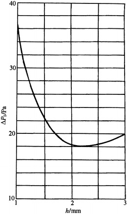
Because of the process that aims to reduce the installation height of filter, the thickness of filter without separator at present is usually less than 80 mm. The relationship between ΔP and h can be calculated, which is shown in Fig. 5.6 (A = 3.5 × 10³).
Fig. 5.6.

Relationship between ΔP and h for HEPA filter without separator (L = 0.08 m, A = 3.5 × 10³)
But now the height of partition line (the height for the adhesion of two lines) is 1.5 mm, instead of 1.14 mm. Other parameters are almost the same as before mentioned values. We can get:
 |
 |
 |
For the common products, A is about 5 × 10³. The theoretical total resistance is about 180 Pa, while the actual resistance of the product is higher than this value by 20 %. Except for the uncertainty of the calculated parameters, there is also space for the discussion in theory.
But 80 mm is not the optimal depth for the case h = 1.5 mm. According to Eq. (5.35), the optimal depth for the case h = 0.0015 mm should be:
 |
After calculation, ΔP = 84.9 Pa, which is smaller than the case L = 0.08 m by 38 Pa. Figure 5.7 shows the relationship between ΔP and L for this kind of filter (A = 3.5 × 10³).
Fig. 5.7.

Relationship between ΔP and L for filter without separator (h = 0.0015 mm, A = 3.5 × 10³)
From the technical and economic point of view, it is still appropriate to choose the depth 0.08 m.
For the corrugated air filter without separator which is made of polypropylene fiber, A = 0.3 × 10³ while other parameters remain the same, we know:
| h = 0.0015 m | L 0 = 0.06 m | ΔP = 24.6 Pa |
| h = 0.001 m | L 0 = 0.032 m | ΔP = 32.6 Pa |
Figure 5.8 illustrates the relationship between ΔP and L (A = 3.5 × 10³). It shows that L = 0.06 m is indeed the optimal value for h = 0.0015 mm.
Fig. 5.8.

Relationship between ΔP and L for sub-HEPA filter without separator (h = 0.0015 mm, A = 3.5 × 10³)
For the sub-HEPA filter without separator when L = 0.08 m, the optimal crest height can be thought as h 0 = 2.2 m from Fig. 5.9 (A = 3.5 × 10³). When in practice h = 1.5 mm, the resistance is higher than that with optimal crest height by 4 Pa, where the difference is very small.
Fig. 5.9.
Relationship between ΔP and h for sub-HEPA filter without separator (h = 0.08 mm)
Calculation of Tubular Filter
If the resistance of filter is required to be lower, one method is to choose filter material with less resistance and the other one is to reduce the structural resistance. The tubular structure may meet the requirement of the second method. Now analysis for the structure of tubular sub-HEPA filter is performed as 10.1007/978-3-642-39374-7_4.
The frictional resistance of inlet passage is supposed to be equal to that of outlet passage, i.e.,
 |
From the process point of view, the tubular diameter which is easy for process is determined at first. The appropriate number of tubes within the area a × b is chosen. Then the total resistance can be calculated with the following expression (refer to Fig. 5.10):
 |
5.36 |
where ΔP 1 is the filter media resistance (Pa)
 |
5.37 |
Fig. 5.10.

Calculation parameters of tubular filter. 1 filtration tube, 2 plug head, 3 vane, 4 frame
ΔP 2(1) is the frictional resistance of inlet passage (Pa), which can be obtained with the method for corrugated filter
 |
ΔP 2(3) is the resistance of inlet perforated plate (Pa)
 |
5.38 |
ΔP 2(4) is the resistance of outlet (Pa).
In the above items, n is the number of tubes;
d is the diameter of tube, m;
v is the filtration velocity, m/s;
v 0 is the inlet velocity of tube, m/s;
d′ is the equivalent diameter of air passage. For the case in Fig. 5.11, the vane is placed in the middle of the tube, where the tubular space is divided into two parts. For half circle, d′ = 0.61d;
u is the velocity at the weather side, m/s;
ζ 1 is the inlet drag coefficient
 |
5.39 |
where c is the contraction coefficient of the pore where air passes through. Usually it is 0.9. When the tubular diameter is as small as 15 mm, filter paper will become corrugated at the throat where the plug is placed. The air passage becomes narrower or even half when c is 0.5.
Fig. 5.11.

Filtration tube with space divided into two parts: 2 plug head, 3 vane
S is the porosity
 |
5.40 |
where
F 1 is the net total area of pores, which is equivalent to the subtraction of the cross-sectional area of vane 0.001d 1 from the total area (which is dependent on the plug diameter d 1 (m), d 1 = d − 0.002 m).
F 2 is the area at the weather side, which is assumed the same as that of corrugated HEPA filter, i.e., 0.484 × 0.484 m2.
Since the outlet of filtration tube is flat, the actual outlet cross-sectional area is very close to that of air filter and it is gradually changed. ΔP 2(4) can be neglected.
Taking the parameters of YGG low-resistance sub-HEPA filter introduced in 10.1007/978-3-642-39374-7_4 as an example, various resistances are calculated with the above method, which is shown in Table 5.5. From this table, the calculated result is very close to the experimental value, which means the calculation method is feasible. It is also shown that with the same dimension and flow rate, the structural resistance of tubular filter is much smaller than that of corrugated filter. At present, due to other reasons, the tubular HEPA filter made of polypropylene fiber has not appeared in the market.
Table 5.5.
Calculation example of tubular filter
| Filtration tube (m) | Number of filtration tubes (#) | Tube lengt (h/m) | Opening area (m2) | Filtration velocity v (m/s) | Face velocity u (m/s) | Velocity v 0 in tube (m/s) | A (Pa·s/m) | C | ζ 1 | S | Calculation result (Pa) | Measured result (Pa) | ||||
|---|---|---|---|---|---|---|---|---|---|---|---|---|---|---|---|---|
| ΔP 1 | 2ΔP 2(1) | ΔP 2(3) | ΔP | ΔP | ΔP 2 | |||||||||||
| 0.019 | 330 | 0.215 | 0.0692 | 0.066 | 1.35 | 4.01 | 5.5 × 10² | 0.9 | 10 | 0.336 | 36.3 | 3.7 | 10.9 | 50.9 | 50 | 13.7 |
| 0.019 | 330 | 0.215 | 0.0692 | 0.066 | 1.35 | 4.01 | 7 × 10² | 0.9 | 10 | 0.336 | 46.2 | 3.7 | 10.9 | 60.8 | 60 | 13.8 |
| 0.019 | 347 | 0.215 | 0.0728 | 0.0624 | 1.35 | 3.81 | 7.5 × 10² | 0.9 | 9 | 0.353 | 46.8 | 3.5 | 9.8 | 60.1 | 60 | 13.2 |
| 0.019 | 347 | 0.215 | 0.0728 | 0.0624 | 1.35 | 3.81 | 5.6 × 10² | 0.9 | 9 | 0.353 | 34.9 | 3.5 | 9.8 | 48.2 | 50 | 15.1 |
| 0.019 | 347 | 0.215 | 0.0728 | 0.0624 | 1.35 | 3.81 | 7.8 × 10² | 0.9 | 9 | 0.353 | 48.6 | 3.5 | 9.8 | 61.9 | 60 | 11.4 |
| 0.015 | 630 | 0.215 | 0.0753 | 0.044 | 1.35 | 3.69 | 7 × 10² | 0.9 | 29.3 | 0.336 | 31 | 5.5 | 31.9 | 68.4 | 75 | 44 |
References
- 1.Cheng DY Fluid dynamics model of air filter. Mech Eng. 1983;1:34–37. [Google Scholar]
- 2.Пречистенский СА (1961) РадиоаkтивHые выбросы в атмосферу, Москва: Γосатом нздат, p 36 (In Russian)
- 3.Institute of HVAC of China Academy of Building Research (1973) Assembly cleanroom (In Chinese)
- 4.Xu ZL Discussion of enlarging the corrugation crest angle of the separator on HEPA filter. J HV&AC. 1991;6:26–28. [Google Scholar]