Abstract
Cleanroom is the most important and most representative measure to create the clean microenvironment with air cleaning technology. The principle of cleanroom is the theoretical base for the design, operation, and maintenance of the cleanroom well.
Keywords: Differential Pressure, Flow Line, Incoming Flow, Unidirectional Flow, Triangular Region
Cleanroom is the most important and most representative measure to create the clean microenvironment with air cleaning technology. The principle of cleanroom is the theoretical base for the design, operation, and maintenance of the cleanroom well.
Approach to Control Contaminants
In terms of the controlled objects, cleanroom can be divided into two kinds: industrial cleanroom and biological cleanroom.
The main task of industrial cleanroom is to control the pollution of nonbiological particles, while that of biological cleanroom is to control the biological particles.
However, no matter it is nonbiological or biological particles, non-vital or vital particles, they are considered to be particles in the air cleaning technology field, which has the feature of particles. Therefore, no matter what kind of cleanroom it is, the approach to control particular pollution is the same. These methods have the following features:
Prevent the outdoor pollution from entering indoors (or effectively prevent indoor pollution from emission outdoors). This is the main approach to control the pollution in the cleanroom, which mainly includes the method of air cleaning and indoor pressurization, etc.
Exhaust the pollution that occurs indoors effectively, which mainly includes the indoor air distribution. This represents the key function of cleanroom.
Control the pollution source and reduce the generation of pollution, which mainly includes the method to place and manage the equipment which generates pollution, as well as the cleaning of people and objects entering into the cleanroom. The former belongs to the process problem, which will not be discussed. The latter will be introduced later.
The above three items will be illustrated in this chapter and later.
Flow State
Several Fundamental Fluid States
In order to illustrate the principle of cleaning function by cleanroom from the airflow aspects, the following concepts of fluid dynamics are emphasized.
Steady-State Flow and Unsteady-State Flow
Various parameters of fluid particles (such as velocity, acceleration speed, density, and stress including the pressure, tension, shear force, and viscous force) differ with position of fluid particles, but remain the same with the time t. This kind of fluid is called steady-state flow. If various airflow parameters are function of both position (x, y, z) and time (t), it is called unsteady-state flow.
Gradually Varied Flow and Mutation Flow
When the flow has the following characteristics, it is called gradually varied flow, which is shown in Fig. 8.1.
The angle β between flow lines is very small, which means the distance between flow lines is almost equidistant.
The radius of curvature R is very large, which means the flow line is close to be straight (combined with the above item, the flow lines are almost parallel). So the inertial force can be neglected.
Fig. 8.1.
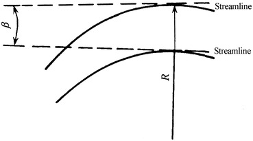
Gradually varied flow
If the flow does not have the above two features, it belongs to the mutation flow.
Uniform Flow and Nonuniform Flow
When the flow of the gradually varied flow has the following features, it is termed as uniform flow:
The shape and scale of the flow at any cross section are the same along the flow stream.
The velocities at any two positions along the same flow line are the same.
It is clear that uniform flow is the limit case for gradually varied flow.
As long as any condition is missing, it is nonuniform flow. The example of the nonuniform flow is shown in Fig. 8.2a which does not have either features. Figure 8.2b shows the example which does not have the second feature at the inlet section. Figure 8.2c shows the example which has both features.
Fig. 8.2.

Uniform flow and nonuniform flow
Laminar Flow and Turbulent Flow
When there is no exchange of fluid particles between fluid layers, it is called the laminar flow, and vice versa, it is the turbulent flow.
For pipeline flow, it is laminar flow when Re number decreases to be less than 2,400. When Re number increases to about 13,800, it becomes the turbulent flow. But the critical value of Re number is usually not fixed. In some cases the flow keeps laminar even if Re number increases to 105. The critical value of Re number for the transition of flow mainly depends on the stability of the incoming flow.
With the state of turbulent flow, fluid particles mix randomly, which differs with the time t. So in fact the turbulent flow is not one type of steady flow.
When a longer time period T is chosen, the average velocity (also called time averaged velocity) can be obtained:
 |
If the condition of incoming flow remains the same (such as the flow rate or disturbance condition), the time averaged velocity can also be unchanged even for turbulent flow, so it is still called steady flow. This means although the transient flow line cannot be plotted for this kind of turbulent flow, the time averaged flow line can be obtained. On the contrary, if the time averaged velocity is unchanged, it is obviously not the steady flow. The field we investigated belongs to the former case.
In cleanrooms, it is turbulent flow in terms of the Re number.
Based on the above analysis, the flow situations can be divided into the following groups:
 |
Physical State of Turbulent Flow
The flow state in cleanroom belongs to the turbulent flow. The physical state of turbulent flow is the fundamental concept of fluid dynamics, which has been introduced in many monographs about fluid dynamics. Here the following two points are emphasized.
Formation Process of Turbulent Flow
- Formation of Eddy
- Viscous Property. In the flow field with relative movement, the shear stress forms between fluid layers because of the viscous property. For one side of fluid layer, the effect of shear stress on it by the fluid layer with relative high velocity is following the flow direction, while that by the fluid layer with relative low velocity is against the flow direction. Therefore, the moment of force and eddy are likely to be formed on this fluid layer.
- Fluctuation Property. If the fluctuation perpendicular to the flow direction occurs by certain reasons, the velocity increases at the convex side since the cross-sectional area reduces by fluid squeezing, while the velocity decreases at the concave side. The difference of velocity at both sides further forms the eddy. Figure 8.3 shows the schematic for the process of eddy formation, where the situation between the fluid line with ordinary turbulence and eddy is presented.
Once the eddy is formed, it detaches from the original fluid layer and enters into the adjacent fluid layer.
Fig. 8.3.

Eddy formation
Once the eddy is formed, the flow direction of fluid layer with higher velocity is consistent with the rotation direction of eddy, and it is opposite for the flow direction of fluid layer with lower velocity. So the velocity of fluid layer with higher velocity becomes larger and that of fluid layer with lower velocity becomes smaller. The pressure reduces at the place where the velocity increases, and the pressure increases at the place where the velocity decreases. So the pressure difference perpendicular to the flow direction is formed. When the force of this pressure difference is larger than that of resistance, the eddy is forced to detach from the original fluid layer and enters into the adjacent fluid layer.
As long as these two conditions exist, which includes the formation of eddy and the entering of eddy into adjacent fluid layer, the exchange of eddy and mutual supply between fluid layers can occur because of the continuity of the flow. The chaos formed will influence the further fluid layer. If many initial eddies are formed, the whole fluid state will change completely.
Properties of Turbulent Flow
With the analysis of physical state about the formation process of turbulent flow, the following conclusions about the feature can be obtained:
Large Re number.
Irregular.
Diffusional.
Eddy flow at three dimensions.
Energy dissipates quickly because of viscosity.
Except for the above features, the turbulent flow is also dependent on the incoming flow condition. If the incoming flow is not uniform, tiny fluctuation can be generated and thus the eddy is formed. This explains the reason why there is no fix upper critical value of Re number.
Principle of Cleanroom with Mixed Flow
Principle of Cleanroom with Mixed Flow
According to the flow state, cleanrooms can be classified as cleanroom with mixed flow (non-unidirectional flow), cleanroom with unidirectional flow, and cleanroom with radial flow (also called vector flow). In this section, the cleanroom with turbulent flow is introduced. As mentioned before, the flow in any kind of cleanroom is turbulent. So why not all of them are called turbulent flow cleanroom?
The term “mixed flow cleanroom” was referred to the Japanese language. In Japanese language, the meaning of mixed flow is the same as the turbulent flow in hydrodynamic field, while it differs in the monograph “Air cleaning technical measures” in China. At present, this kind of cleanroom is customarily called non-unidirectional cleanroom.
There are various kinds of air supply for mixed flow cleanrooms:
Ceiling supply air with HEPA filter (with or without diffuser plate), shown in Fig. 8.4a
Ceiling supply air with streamlined diffuser, shown in Fig. 8.4b
Ceiling supply air with local perforated plate, shown in Fig. 8.4c
Sidewall supply, shown in Fig. 8.4d
Fig. 8.4.
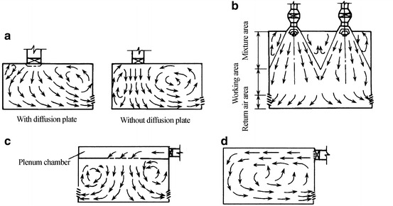
Air supply form of mixed flow cleanroom. (a) Air supply through HEPA filter ceiling. (b) Air supply through concentrated streamlined diffuser ceiling. (c) Air supply through local perforated plated ceiling. (d) Side air supply
When the flow type is determined on the Re number, it is obvious that all these cleanrooms have the turbulent flow. But it is inappropriate to call them turbulent flow cleanroom. Take the type in Fig. 8.5 as an example, when air is supplied from all the ceiling with the velocity more than 0.25 m/s, it is also turbulent. But it will be illustrated later that although both two kinds of air supply cause turbulent flow in the room, their principles to clean indoor air are different, because for the latter case, the principle of cleanroom with unidirectional flow or parallel flow applies. Therefore when the former case is called turbulent flow cleanroom, the latter case should also be included.
Fig. 8.5.
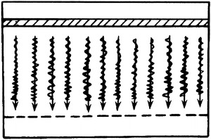
Unidirectional flow of turbulent flow
It is shown in Fig. 8.4 that the main feature of mixed flow cleanroom is that the cross-sectional area changes along the flow stream from the incoming flow towards the outlet flow (from air supply inlet to return air grille). Since the cross-sectional area of cleanroom is larger than that of air supply inlet, uniform flow cannot be formed at the whole cross section or at the cross section of working area. The streamlines after leaving the air supply inlet will have a large included angle which will become larger and larger. The radius of curvature is very small, so air cannot flow unidirectionally in the room, and steamlines will impact on each other, which generates the backflow and vortex. This results in the essence of flow state in the mixed flow cleanroom: mutation flow and nonuniform flow.
It is more accurate and comprehensive to describe the cleanroom with the mixed flow instead of with turbulent flow. Turbulent flow is mainly dependent on Re number, which is mainly influenced by the velocity. If the ceiling supply air with HEPA filter was used, the above consequences will occur even for extreme low velocity, because it is mutation flow and nonuniform flow. Therefore in this case, the mixture occurs between fluid layers not only because of turbulent flow but also because of the backflow and vortex in the whole room.
To summarize, the principle of mixed flow cleanroom is that when a certain amount of clean air is supplied into the room, it will disperse and mix with the surrounding air, and at the same time the same amount of air is exhausted from the return air grille. The clean air dilutes the indoor polluted air, which reduces the indoor pollution concentration from original state and arrives at the equilibrium state. Therefore, the faster and the more uniform the air diffuses, the better the effect of dilution it is.
So the principle of mixed flow cleanroom is the effect of dilution. Figure 8.6 shows the general situation of this principle.
Fig. 8.6.
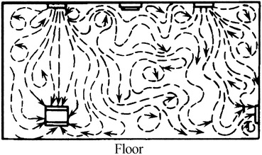
Schematic for the principle of mixed flow cleanroom
Air Inlet in Mixed Flow Cleanroom
Air Supply Outlet
According to the principle of mixed flow cleanroom, if low particle concentration in the whole room, instead of only the region below the air inlet, is needed, the clean air should play the role of dilution sufficiently after leaving the air inlet, and more space before the working area is diluted. So this kind of air inlet should have the enough capability of dilution. If the air inlet has high velocity and small diffusion angle as shown in Fig. 8.7, the proportion of clean air is likely to be exhausted from the return air grille directly, and its capability of dilution in other space is not shown.
Fig. 8.7.
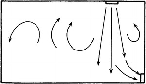
Air distribution with poor performance of dilution
Usually the air supply inlet with HEPA filter has the diffusion angle of tens degrees, which are shown in Figs. 8.8 and 8.9. However, when the perforated diffusion plate with the thickness of 65 mm is added, the diffusion angle can be as large as 45° or even larger according to the air flow test abroad, which is shown in Fig. 8.10. In this case, the velocity near the air supply inlet is more uniform than that without diffusion plate.
Fig. 8.8.
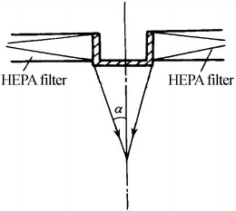
Dispersion angle of supplied air through HEPA filter
Fig. 8.9.
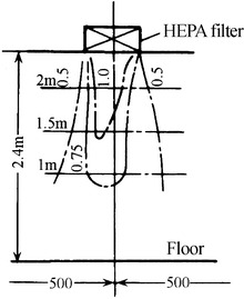
Velocity field with HEPA filter air supply outlet without diffusion plate
Fig. 8.10.
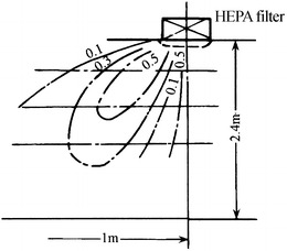
Velocity field with HEPA filter air supply outlet with diffusion plate
According to the experiment performed by No. 10 Design Institute of the former Fourth Ministry of Machinery and Industry, under the same air change rate, the ratio of average particle concentration in the working area of the cleanroom and the concentration at the return air grille, for the case with the HEPA filter air supply inlet and nonuniformly perforated diffusion plate, is 20 % less than that without this kind of diffusion plate. It means the air inlet with this kind of diffusion plate can dilute the whole room air very well, which makes the indoor particle concentration more uniform and the average concentration much lower. Since this kind of diffusion plate has nonuniform perforation, it is much difficult to manufacture, so it is less popular compared with the diffusion plate with uniform perforation.
However, because of the attenuation effect of hole, the velocity at the four sides of diffuser outlet becomes small. So the region below the ceiling between two air supply outlets is likely to be stagnant, which is not good for the dilution of mixed flow. Therefore one kind of air supply outlet appears as shown in Fig. 8.11. Except for the orifice below the outlet, slot outlets are placed at four sides. The upper velocity is 3 times more than the middle velocity, so that the clean air can arrive at the corner of cleanroom and the air stagnant region is eliminated.
Fig. 8.11.

Diffuser outlet with slot and orifice: 1 orifice, 2 slot outlet, 3 ceiling, 4 side (inclined or vertical)
Return Air Grille
In order to remove indoor particles rapidly and effectively, return air grilles should be placed at the underpart of the room, so that the flow direction is consistent with that of particle deposition. As mentioned in 10.1007/978-3-642-39374-7_6 that the difference between particle velocity and flow velocity is very small, so particles can be removed towards the return air grille easily because of the consistence between flow direction and particle deposition direction. Therefore, the upper supply and bottom return mode is usually used in cleanroom, which is a fundamental principle of cleanroom.
The upper side of return air grille at the underpart of the room should not be too high from the floor. Since the working area starts from 0.7 m above the floor, so the upper side of return air grille should be lower than this level, and the minimum safety distance should be 0.2 m. Otherwise, except for the air above the working table flows through it, air from other places will also pass through, and the working table will be polluted. The related experimental analysis will be presented in Sect. 8.8 in this chapter.
If the return air grille is placed on the upper side of the room, i.e., the upper supply and upper return mode, the following three phenomena will occur at least:
At a certain height such as the respiratory height, big particles with diameter 5 μm are popular. So it is qualified up to the standard in terms of 0.5 μm, while it is not qualified in terms of 5 μm.
For application with local cleanliness of Class 100, the velocity at the working area is usually very small, so it is difficult to be qualified.
The self-purification period is very long. Experiment has shown that it is two times longer. (the self-purification period will be introduced in the latter chapters).
Therefore, although the designed air cleanliness level can be reached for the as-built test with the upper supply and upper return mode, it is very unfavorable to remove pollutant in the operational status. It is not recommended to adopt this mode for the following reasons:
With the upper supply and upper return mode, the air of a certain region at the certain height is likely to be stagnant. When the buoyant force of the particle is balanced with the gravitational force, large particles (mainly particles with diameter 5 μm) are apt to stay in this space, which is not good for particle removal, and the velocity at the working area is not guaranteed (for local Class 100 cleanroom).
The shortcut of airflow is easily formed. Part of the clean air and fresh air will not be efficiently used in the room, so the cleaning and hygiene effect is reduced.
Pollutant particles are likely to pass through the working place during the process of removal. According to the item 17.25 of GMP by WHO, “the airflow in the cleanroom should be verified that no pollution risk exists, for example, particles generated by occupant, operation and machine should not disperse into the high risk region close to the product.” However, there is the risk for this upper supply and upper return mode. For the clean corridor, there is no working place, so there’s no risk of this kind for upper supply and upper return mode. When there is no special cross contamination between the rooms at two sides, it is permissible to use the upper supply and upper return mode.
Effect of Mixed Flow Cleanroom
According to the principle of mixed flow cleanroom, the corresponding limit for air cleanliness level has been calculated. As proved by practice, the highest level of air cleanliness is Class 1000. In order to obtain Class 100 or even higher, only unidirectional flow cleanroom should be used. In the related chapters about cleanroom calculation, this will be discussed in detail.
Principle of Cleanroom with Unidirectional Flow
The unidirectional (parallel) flow cleanroom appeared in the USA in 1961 at the earliest, which was called laminar flow cleanroom. The appearance of this kind of cleanroom is an important milestone in air cleaning technology field. It makes the creation of extreme clean environment possible.
Classification of Unidirectional Flow Cleanrooms
Unidirectional flow cleanroom can be divided into two main categories:
Vertically Unidirectional Flow Cleanroom
HEPA Filter Air Supply Outlet Fully Placed at the Ceiling and Return Air Grille Fully Placed at the Floor
This is the typical type of vertically unidirectional flow cleanroom, which is shown in Fig. 8.12.
Fig. 8.12.
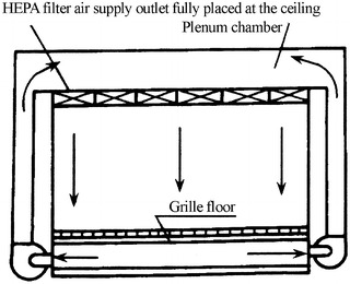
Vertically unidirectional flow cleanroom with HEPA filter air supply outlet fully placed at the ceiling
The feature of this kind cleanroom is that uniform parallel unidirectional air flowing downwards can be obtained. The self-purification ability is very good. The highest cleanliness level can be achieved. The processing equipments can be arranged in any place. The facility to clean the occupant can be simplified. For example, the airshower is not necessary and workers can wear long smock. But the ceiling structure is complex, and the construction and maintenance costs are very high. It is difficult to prevent the leakage on HEPA filter. Figure 8.13 is the scenograph of this kind of cleanroom.
Fig. 8.13.
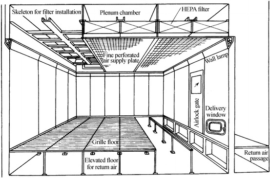
Scenograph of vertically unidirectional flow cleanroom
Leakage-Preventing Layer Air Supply at the Ceiling with HEPA Filter Installed at the Side and Return Air Grille Fully Placed at the Floor
The main shortcoming of vertically unidirectional flow cleanroom is the high construction cost. One of the main reasons is that HEPA filters are placed fully at the ceiling. The role of HEPA filters is to distribution air and filter particles. In order to further make the airflow uniform and the ceiling artistic, the leakage-preventing layer with grille and orifice is placed below the HEPA filter. If the cleanroom area is very small, the airflow rate is not large, and the room width is not large, HEPA filters can be installed at the side as recommended by AACC CS-6T, which is shown in Fig. 8.14. However, it is not easy to meet the requirement of flow rate for the area of HEPA filters installed at the side, especially when the flow rate should not be larger than 80 % of the rated flow.
Fig. 8.14.
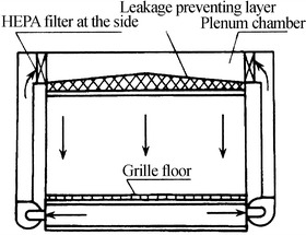
Leakage-preventing layer air supply at the ceiling with HEPA filter installed at the side
When HEPA filters are placed at the side, the metal orifice plate plays the role of distributing the air. This orifice plate is termed as “leakage-preventing layer.” The leakage-preventing layer should also guarantee the uniformity of parallel unidirectional flow, so the aperture ratio should be larger than 60 % (it will be illustrated in detail later). In the same technical requirement of Class 100 unidirectional cleanroom by the USA was given [2].
Materials which contain particles itself cannot be used as the leakage-preventing layer, such as the nonwoven cloth. Except for the metal pore plate, other materials with good air permeability such as the nylon yarn can be used. For example, nylon yarn is fastened to the frame which is placed onto the ceiling skeleton [3]. The skeleton is made of light metal material, so it is easy to install and uninstall. The pressure drop for this kind of nylon yarn (diagonal grain or twill) and nylon screen (pore size ≥ 100 μm × 100 μm) at the velocity 0.01 m/s is about 2–3 Pa. Because of the small pressure drop for these materials, the space between itself and HEPA filter is not closed. There is a great disadvantage that particles will inevitably deposit on the interior surface of this space.
HEPA Filter Air Supply Outlet Placed at the Ceiling and at the Side and Return Air Grille Fully Placed at the Floor
This kind of vertically unidirectional flow cleanroom is the comprehensive of two air supply and return modes [1, 4]. This kind of vertically unidirectional flow cleanroom was firstly adopted in the USA for cleaning the container filled with moon rocks. The purpose is not only to obtain high cleanliness but also to reduce the frequency of changing HEPA filters at the ceiling. The ceiling can be regarded as the semipermanent ceiling. Figure 8.15 shows the schematic of the cleanroom designed in China. It is obvious that it will not be used under usual condition.
Fig. 8.15.
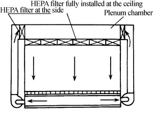
Vertically unidirectional flow cleanroom with HEPA filters placed at both sides
HEPA Filter Air Supply Outlet Fully Placed at the Ceiling and Return Air Grille at Both Sides
The other reason of high construction cost for vertically unidirectional flow cleanroom is to use grille floor. Usually this kind of floor is made of cast aluminum, plastic, and steel. Figure 8.16 shows the photo of grille floor with cast aluminum in the first fabricated cleanroom in China. People do not feel comfortable by vision, since both walking and placing objects seem unstable and tiny objects are likely to fall down underground. Therefore, this kind of floor is not good for promotion of vertically unidirectional flow cleanroom. To improve the air return mode by this kind of grille floor, the mode with HEPA filter air supply outlet fully placed at the ceiling and return air grille at both sides appears, which is shown in Fig. 8.17. Abroad, it is called quasi-laminar flow cleanroom. It is thought to be able to provide the environment with air cleanliness Class 100 when the width is only 3.6 m (USA) [2]. It is also believed to provide the environment with air cleanliness Class 1000 (former Soviet) [6]. Studies at home evaluated this kind of cleanroom comprehensively from theory, experiment, and actual application for the first time [7]. It is concluded that when the distance between two return air grilles is within 6 m, unidirectional flow with cleanliness Class 100 can be obtained (illustrated later in detail).
Fig. 8.16.
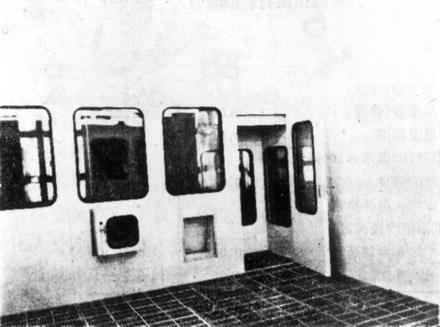
Grille floor with cast aluminum
Fig. 8.17.
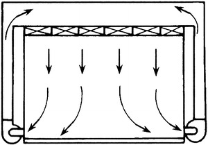
Cleanroom with return air grille at two sides
HEPA Filter Air Supply Unit Fully Placed at the Ceiling and Return Air Grille at the Floor or Both Bottom Sides
The way of air supply in this kind of cleanroom is different from that of common HEPA filter air supply. Instead, HEPA filter air supply unit is used, which can be divided into two types:
-
Fan filter unit – abbreviation form is FFU.
The unit is composed of one fan and one filter. Several FFUs are placed at the ceiling as the air supply outlets. The feature is that air supply and return pipelines are not needed, and most air needed in cleanroom is circulated by FFU. Fresh air is treated for temperature and humidity control in a central way. When the load is not enough, additional dry cold coil can be placed at the return air passage, which is shown in Fig. 8.18. The shortcoming is that the failure rate is large because of so many fans. Since both fan and filter are placed in a box, the air cleanliness will be affected during the maintenance of fans, and it is a little difficult to maintain it in the ceiling.
-
Fan module unit – abbreviation form is FMU.
One fan corresponds to several air filters, and the fan chamber is separated from the air filter chamber. Also supply and return pipelines are not needed. But the shortcoming of FFU does not appear here. Its energy consumption is lower than that of FFU. It is easy to maintain. It is shown in Fig. 8.19.
Fig. 8.18.
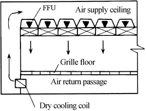
FFU fully placed at the ceiling
Fig. 8.19.
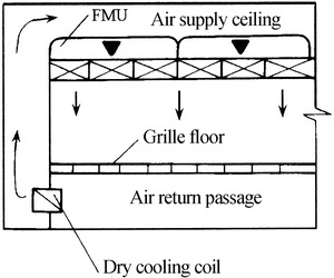
FMU fully placed at the ceiling
Leakage-Preventing Layer Air Supply Outlet Fully Placed at the Ceiling and Return Air Grille on the Floor or at Both Bottom Sides
It is an air supply mode to get rid of the shortcomings by the terminals with HEPA filters. It is abbreviated with “clean air supply ceiling with leakage-preventing layer,” which will be introduced in 10.1007/978-3-642-39374-7_15.
Horizontally Unidirectional Flow Cleanroom
Horizontal Air Supply with HEPA Filters Fully Placed at the Side Wall and Return Air Fully Placed at the Side Wall
This is a typical type of horizontally unidirectional flow cleanrooms, which is shown in Fig. 8.20. Fine air filters are usually installed at the return air wall in the cleanroom. But for the cleanrooms with certain purpose, such as cleanrooms for pharmaceutical production and bacteria cultivation, HEPA filters are installed on the wall for return air and fine air filters on the wall for supply air under the full circulation situation, so that pollutant particles generated from the operation indoors will not influence the pipeline system and these particles can be collected for centralized process.
Fig. 8.20.
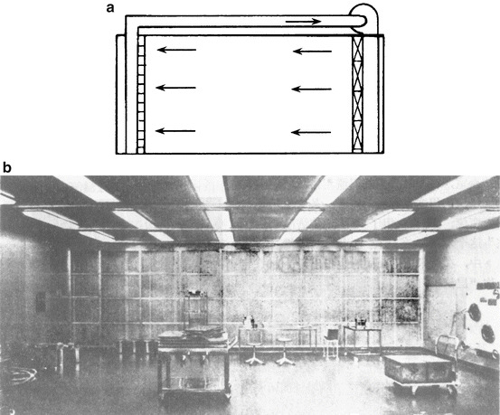
Horizontally unidirectional flow cleanroom. (a) Typical structure. (b) Scenograph
The characteristic of this kind of cleanroom is that the environment with highest cleanliness can only be obtained in the first working area (the concept of first working area will be introduced in 10.1007/978-3-642-39374-7_17). When air flows to other side, the particle concentration increases gradually, which is suitable for the application of multiple air cleanliness levels. It is obvious that the construction cost is lower than vertically unidirectional flow cleanroom.
“Tunnel” Unidirectional Flow Cleanroom
This kind of cleanroom is shown in Fig. 8.21. The difference with the above kind is as follows:
On the opposite wall of the supply air wall which installs HEPA filters, there is no return air wall. It is open to the outside.
There is no circulation air, and indoor air is exhausted to the surrounding environment.
For this kind of cleanroom, it is not the elevated pressure that prevents the pollution from surrounding environment; instead, it is the air velocity that prevents the invasion of pollution.
The temperature and humidity indoors should be the same as that of the surrounding environment.
Fig. 8.21.
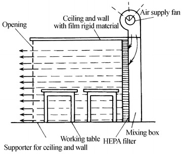
“Tunnel” unidirectional flow cleanroom
It is customary to call it the “tunnel” unidirectional flow mode, which is the cheapest of unidirectional flow cleanrooms and is portable. It is especially useful for the assembly of large-scale equipment and temporary maintenance.
Principle of Unidirectional Flow Cleanrooms
Fundamental Principle
According to various kinds of unidirectional flow cleanrooms mentioned above, the cross-sectional area almost remains the same along the flow passage from the air supply outlet and return air grille in the cleanroom. Besides, with the uniform effect by the plenum chamber and HEPA filter, velocity at the cross section is comparatively uniform. At least in the working area, the streamlines are parallel and unidirectional, and vortex does not exist. These are the three characteristics of unidirectional flow cleanrooms. That the streamlines are parallel and unidirectional means the time averaged streamlines are parallel with each other and the direction is unique, which are shown in Figs. 8.22 and 8.23.
Fig. 8.22.

Schematic diagram of time averaged parallel flow
Fig. 8.23.
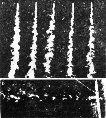
Actual photo of the time averaged flow in unidirectional flow cleanroom. (a) Vertical unidirectional flow. (b) Horizontal unidirectional flow
As mentioned in the previous section, the flow in unidirectional flow cleanroom is turbulent in terms of Re number. So the concept of “laminar flow” in the so-called laminar flow cleanroom is completely different from that of fluid dynamics. Therefore, it is inappropriate to use the name “laminar flow cleanroom.” This has also been pointed out in some standards and papers abroad. For example, British Standard BS-5295 defines the “laminar flow cleanroom” as “unidirectional flow cleanroom,” where the laminar flow is marked in the bracket to take account of the habit. The former German Federal Standard VDI-2083 adopts the term “nonturbulent replacement flow,” where the concept of laminar flow is used to distinguish from the mixed flow cleanroom which appeared before. The exact meaning of “laminar flow” is not stratified flow but is the replacement flow of turbulent flow. It is the gradually varied flow of turbulent flow in this chapter. In German Standard DIN1946-4 published in Dec. of 2008, the laminar flow region is divided into “laminar flow” and “low turbidity flow” (LTF). In the field of hydrodynamics, it is also termed as parallel flow or unidirectional flow. In 1977 the term “parallel flow” was adopted in the monograph “measures of air cleaning technology,” where the customary term “laminar flow” was also mentioned. In Sweden Standard “Mikrobiologisk renheti operationsrum” published in 2011 also adopted the concept of “parallel flow,” which is defined as the air flows in a certain (same) direction.
In unidirectional flow cleanroom, the cross section of whole room is full of the clean air. So it is not the mixed dilution effect of clean air on the polluted air indoors but the pushing effect of the clean air which exhausts the polluted air indoors towards outdoors, so that the indoor air is cleaned. Therefore, the flow in unidirectional flow cleanroom was called “piston flow” and “pushing flow” in the former Federal Germany [8]. In the former Soviet, it was called “jet of squeezed air” [9]. Clean air is similar as an air piston, which pushes forward along the room as the cylinder. Particles are forced to move forward, and the air with high particle concentration is squeezed out of the room. The process of the squeeze is shown in Fig. 8.24.
Fig. 8.24.

Schematic diagram of the principle for unidirectional flow cleanroom
In the unidirectional flow cleanroom and equipment, the reversed flow appears along the wall and the region under the connection of two filters. This kind of flow brings the pollution from downwards to upwards, which damages the status of “piston flow” and is very harmful. For the locally cleaning equipment with open outdoors, such as the cleaning bench, this kind of flow will induce the polluted air outdoors, which is shown in Fig. 8.25. Therefore, the noneffective area occupied by the filter frame must be reduced during the design, and the wall should be as close as possible to the effective air supply cross section of air filters.
Fig. 8.25.
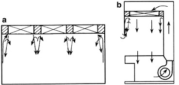
Locally reversed flow. (a) Cleanroom. (b) Clean working bench
According to the above analysis, two preliminary conditions should be met to guarantee the feature of unidirectional flow cleanroom (high level of air cleanliness and fast self-purification ability): (1) the air cleanliness level of incoming flow and (2) the status of piston flow from incoming flow.
As for the air cleanliness level of incoming flow, it is not a problem for the unidirectional flow cleanroom when HEPA filter air supply unit is used. But as for the status of piston flow from incoming flow, further analysis is needed.
According to the principle of fluid dynamics, the status of incoming flow will have important influence on the future flow directly. Air from the air supply outlet is the incoming flow of the working area.
When the turbulent fluctuation of the incoming flow is large, it will influence the characteristic of unidirectional flow in the future. When the cross section is not filled with the incoming flow, it will affect the formation of “piston flow” and the speed of formation. That the cross section is not full of the incoming flow is also one factor of the turbulent fluctuation for the incoming flow. Therefore, when HEPA filters are installed, the essential condition for keeping the characteristic of unidirectional flow cleanroom is “piston flow.” The essential condition of “piston flow” is that the cross section is full of the incoming flow. However, compared with the pipeline, it is impractical to make the cross section full of the flow from the air supply outlet to the air exhaust grille for the whole room.
At first, it was thought that parallel unidirectional flow should fill in the whole cross section of cleanroom, which is not unfavorable from the technical and economic point of view. With the development of understanding, this kind of unidirectional flow was believed to mean all the air in a certain limited region flows parallel with a constant velocity, which could be used to restrain the generation of vortex. The room where the characteristic of unidirectional flow with clean air in the whole space is dominant can also be called “unidirectional flow cleanroom” [10]. This means that it is not required that the whole room is full of parallel unidirectional flow with uniform velocity and without vortex, but it is only required that the characteristic of unidirectional flow is dominant in the room. For example, when the flow in the space of working area is unidirectional, the room is a unidirectional flow cleanroom. The high level of air cleanliness, which is for unidirectional flow cleanroom mentioned before in related standard and measures at home and abroad, means the air cleanliness level achieved in the working area. Therefore, the measures to install streamlined diffuser intensively and full orifice supply at the ceiling are also considered to be the way to realize the vertically unidirectional flow.
In the space navigation auxiliary building for the Mars Explorer built in Feb. of 1971, the height of the room is 15 m, and streamlined diffusers were installed intensively. Unidirectional flow becomes dominant at 1.93 m distance below the air supply outlet, which provides the air cleanliness level with Class 100 [12].
In order to improve the airflow situation under the frame of air filters, wedge can be placed under the frame of filters. The angle of the wedge is about 20°, which is shown in Fig. 8.26 [11]. Special attention should be paid on these palaces during the test. If high concentration appears locally, the above reasons should be considered.
Fig. 8.26.
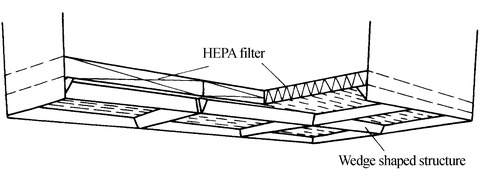
Wedge installed under the frame of filters
Main Features
Understanding of the above concepts is beneficial for the development of unidirectional flow cleanrooms. But two main features should also be emphasized:
In the past, parallel flow was emphasized in unidirectional flow cleanrooms, while the parallel of time averaged flow lines was not pointed out. Since the flow in unidirectional flow cleanrooms is still turbulent in nature, it is impossible for the instant flow lines to be parallel as the laminar flow in the fluid dynamics. It is only required that polluted air can be exhausted at the same time along all cross sections in this kind of cleanroom, so time averaged parallel flow lines are enough.
In the past, unidirectional flow was emphasized in unidirectional flow cleanrooms, so that the secondary contamination caused by backflow can be avoided. However, since the actual cleanroom is not empty, the flow cannot be unidirectional absolutely. In order to avoid backflow and vortex generation, the radius of curvature should be small and the angles between flow lines should be small, which means the gradually varied flow can meet the requirement of this kind of cleanroom. Therefore, the gradually varied flow is the actual status existing in unidirectional flow cleanrooms.
Therefore, when the dominant flow in cleanrooms is uniform flow or gradually varied flow, it can be called unidirectional flow cleanroom. This means when the working area (the space between 0.7 and 1.5 m above the floor) is full of unidirectional flow, this cleanroom can be treated as unidirectional flow cleanroom.
In order to obtain this effect, the area of HEPA filters horizontally placed in the plenum chamber at the ceiling should occupy a certain proportion of the total area. The ratio is defined as “ratio of blowing area”
 |
Under usual situation (when only the frame between filters and wall is subtracted), the “ratio of blowing area” ≮80 %.
The minimum value (when a certain amount of air filter is still installed):
For vertically unidirectional flow, the “ratio of blowing area” ≮60 %.
For horizontally unidirectional flow, the “ratio of blowing area” ≮40 %.
For the decoration layer parallel to the air filter, or the so-called damping layer, its pressure drop is extreme low and it is close to the air filter, so the space between it and the air filter cannot be similar as the plenum chamber. If the “ratio of blowing area” for air filter is very small and at the same time the permeability area ratio of the damping layer (which means the ratio of clean air passage area to the whole cross-sectional area) is large, i.e., the “ratio of blowing area” for the clean air is larger than that of the air filter, clean air flow lines will connect with each other at the lower position, which is not helpful for the formation of “piston flow” in advance, which is shown in Fig. 8.27.
Fig. 8.27.
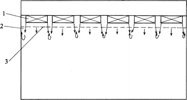
The situation which is not helpful for the formation of “piston flow” in advance. 1 HEPA filter, 2 dead zone by damping layer, 3 decoration damping layer with small resistance
On the contrary, if the “ratio of blowing area” for the clean air is smaller than that of the air filter, air filter cannot play its role properly. But when the damping layer is the orifice plate whose porosity cannot be very large, there is a problem of jet flow lapping after the jet leaves the pore. The allowable porosity should be larger than 60 %.
There must be a certain amount of height for the combination of the plenum chamber and air filter. For HEPA filter with isolator, the height reaches 800 mm. For HEPA filter without isolator, the height reaches more than 600 mm. When the height for installation is not enough, HEPA filters were reported to be installed at the side instead of being installed horizontally. In most cases, HEPA filters cannot be installed properly at the side, and the airflow rate and the pressure drop have to be increased. Moreover, since the pressure drop of the decoration layer, i.e., the damping layer, is very small, the airflow inside the plenum chamber is very turbulent because of the side arrangement of air filters, although the “ratio of blowing area” for the clean air may be large. The turbulent incoming flow will influence the characteristic of unidirectional flow downstream greatly. Even for this case, the “ratio of blowing area” for air filters is expected to be more than 80 % with this installation mode (corresponding to the side cross-sectional area). Otherwise, the incoming flow will be more turbulent, which may cause backflow.
When HEPA filters are installed outside of the plenum chamber and the leakage-preventing layer is used at the surface of air supply outlet, the leakage-preventing layer has a certain value of pressure drop and good performance of comprehensive permeability and filtration of submicron particles (shown in 10.1007/978-3-642-39374-7_15), so the continuous clean space between HEPA filter and leakage-preventing layer is formed, and it is a closed system before the air supply outlet. Therefore, the damping layer is actually the extension of the HEPA filter terminals. The area of air permeability of the damping layer can be treated equal with that of air filters. The “ratio of blowing area” can be expressed as:
 |
Three Characteristic Indexes for Unidirectional Flow Cleanroom
The feature of unidirectional flow has never been completely and quantitatively described. Until the later twentieth century, ISO 14644-3 only generally points out that unidirectional flow is defined as “the controlled flow is parallel at the whole cross section of the cleanroom, and the velocity is stable.” Three characteristic indexes describing the performance of unidirectional flow are proposed in the Chinese version of “Principle of Air Cleaning Technology” published in 1983, including the parallel degree of flow lines, the turbidity, and the lower-limit velocity. In order to realize the purpose of the unidirectional flow cleanroom, these three indexes must be satisfied.
Parallel Degree of Flow Lines
It is not easy for the flow lines to be unidirectional and parallel with each other completely for the unidirectional flow cleanroom. As mentioned before, the gradually varied flow can meet the requirement. The problem is that what the allowable extent of the streamline inclination angle is.
The purpose of the parallel flow lines is to prevent the particles from dispersion in the direction which is perpendicular to the flow direction. If this kind of dispersion is within the allowable range, the slight inclination of the flow lines is also allowable. Therefore, for the unidirectional flow cleanroom, there is a problem about the allowable parallel degree for the flow lines.
At first, take a look at the specification of the working area in the cleanroom at home and abroad, which is shown in Table 8.1.
Table 8.1.
Specification for the range of the working area
| Country | Above floor (cm) | Below ceiling (cm) | Working height (cm) | Remark |
|---|---|---|---|---|
| USA | 76 | 92 | 102 | Minimum room height 2.7 m |
| China | 80–150 | 70 |
It is shown from the table that the height of the unidirectional flow cleanroom should not be less than 2.7 m, which means the clear height of the working area in the American specification is comparatively large. The working area is the region where the main process occurs. So the air cleanliness level is expressed with the particle concentration in the working area. However, some auxiliary operations may occur in the place where it is above the working area, for example, opening the valve or screwing the component. Given the common height of the cleanroom and the convenience of the occupant operation, the height of these auxiliary operations and the equipment is usually less than the occupant height, which is about 1.8 m.
The lower limit of the working area specified in “Air Cleaning Technology Measures” was 0.8 m. Here the more stringent value 0.75 m is used (the height of the working table can be lower than this value).
When the staff stands up to operate, particles are released at the height of 1.8 m above the floor. It is expected that when these particles fall to the height of 0.75 m above the floor, they will not enter the region of adjacent staff which is outside of the working area of this staff, which will cause pollution. From Fig. 8.28, it is shown that the maximum distance between the people and the two sides is about 50 cm, when the operational area of the staff is in the middle of the table. If particles, released at the place where it is 1.05 m above the table, are still within the operational area during its fall down to the height of the table when people stand up to operate, the adjacent area will not be polluted. In this case, when the flow is inclined straight lines, the inclination angle between the flow line and the horizontal should be larger than  . For horizontally unidirectional flow cleanroom, the above value of 1.05 m can meet the requirement of the length for the first working table. So this angle of inclination can also be valid for horizontally unidirectional flow cleanroom.
Fig. 8.28.
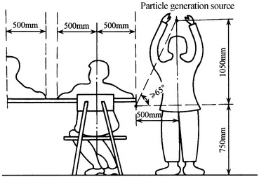
Crosswise pollution distance for vertically unidirectional cleanroom
If the flow lines are the profile of gradually varied flow, the angle between it and the lower-limit surface of the working area, as well as between it and the connection line with the upper-limit surface at the height 1.05 m, should be larger than 65°, which is shown in Fig. 8.29.
Fig. 8.29.
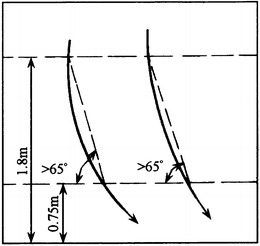
The inclination angle of the gradually varied flow lines
In the specification of acceptance check for Class 100 unidirectional flow cleanroom in the USA [2], the requirement for the parallel degree of flow lines is as follows: For the region where is 92 cm below the ceiling and 76 cm above the floor, the horizontal component of velocity should not be so large that the distance of particle dispersion is larger than 60 cm. But there’s no reason to explain about this specification. Since the height of cleanroom is 2.7 m, the inclination angle of the flow lines can be obtained. It is about 61°, which is 4° smaller than the calculation result above. It is obvious that the requirement based on the above calculation is much higher.
According to the requirement of the parallel degree and angle, the inclination angle of each flow line should be larger than 65°, and the angle between two adjacent flow lines should be as small as possible. For example, when the angle between two closing flow lines changes from 65° to almost 90°, the flow status will change intensively and thus the vortex will be generated. In the extreme case, the angle of two flow lines is (90°–65°) = 25°. According to the illustration about the horizontal dispersion distance, the distance should not be less than 0.5 m, which is shown in Fig. 8.30. Therefore, there are two aspects for the requirement of the parallel degree: (1) the minimum of the inclination angle is about 65° and (2) flow lines incline gradually from the vertical position, and the extent of the inclination that equals to the increase of the angle per unit centimeter distance is less than 0.5°.
Fig. 8.30.
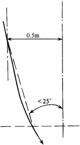
Angle of flow lines
Turbulence Intensity
As mentioned before, it is required for the indoor air to be uniform flow based on the essence of unidirectional flow cleanroom. Since various cross-sectional areas are the same along the streamline for uniform flow, the flow fields at each cross section are uniform. It is extremely important for the flow field to be uniform in the uniform flow cleanroom. Nonuniform flow field will increase the fluctuation of velocity, which promotes the mixture of fluid particles between fluid lines. If the flow field is nonuniform, obviously, the difference between the maximum and the minimum velocities will be large, which will generate large vortex indoors.
Fluctuation Velocity
The air velocity at a certain place indoors is not constant. When accurate velocimetry is used, the change of velocity with time can be measured, which is shown in Fig. 8.31. At any time t, the velocity u can be thought to be composed of two parts, i.e.,
 |
8.1 |
where
 is a positive constant value;
Δu changes with time t. It may be positive or negative, large or small. For a longer time, the time averaged value
 is zero.
u is called the transient velocity,
 is called time averaged velocity, Δu is called fluctuation velocity. When the velocimetry with needle is used, only the time averaged velocity can be obtained.
Fig. 8.31.
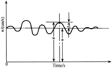
Fluctuation of velocity field
Although the fluctuation velocity may be positive and negative from time to time, the frequency of the fluctuation velocity with the smaller absolute values is large, and that with the larger absolute values is small. Normal distribution can be used to describe the variation pattern of time averaged velocity [13], which is shown in Fig. 8.32.
Fig. 8.32.
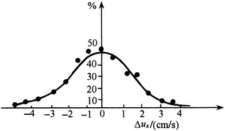
Change characteristic of fluctuation velocity
The normal distribution feature of the fluctuation velocity also results in the normal distribution of transient velocity. The fluctuation of velocity field in the room with air-conditioning system was measured and presented in Fig. 8.33 [14]. The abscissa is the time. The former five data are corresponding to 1 s. The total sampling time is 222 s. The ordinate is the flow velocity. The time averaged velocity of this flow field is  m/s, and the maximum fluctuation velocity is Δu
max ≈ 0.1 m/s.
Fig. 8.33.
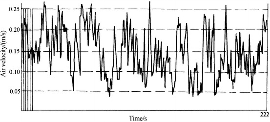
Experimental data of the velocity
With the total number of 222 s, the proportion of each time period with this total number can be calculated, which can be plotted with the statistical data of velocities on the normal probability paper in Fig. 8.34. It is shown from the approximated linear line that the characteristic of the velocity meets the normal distribution.
Fig. 8.34.
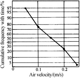
Characteristic of the velocity change with time
There are many reasons for the fluctuation of indoor air velocity. Both the characteristic of air supply outlet and the air distribution will pose influence, and the supplied air itself is also one factor. For example, the periodic change of the gap between the fan blades will also play a role in the fluctuation of airflow.
Next the influence of the fluctuation velocity will be investigated. Suppose the time averaged velocity at the place A in the flow field is  , which is shown in Fig. 8.35. The fluctuation velocities at the x- and y-directions are Δu
x and Δu
y, respectively. According to fluid dynamics, for the tiny area ds with the center located at A, the fluid transport mass per unit time from layer A to the adjacent layer B is ρΔu
yds. Since there is the fluctuation velocity along x-direction, the momentum in this direction is ρΔu
ydsΔu
x. The force exerted on the place B by this momentum in this direction is ρΔu
xΔu
yds. Therefore, the shear stress generated by the fluctuation velocity is:
 |
8.2 |
Fig. 8.35.
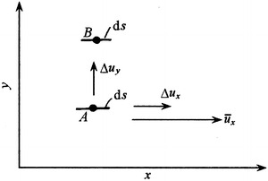
Influence of the fluctuation velocity
The time averaged value is:
 |
8.3 |
This is a kind of attached shear stress. The real shear stress for the velocity with fluctuation can be obtained when the pure viscous shear stress is added [15]:
 |
8.4 |
Because of the continuity of the fluid, when the fluctuation velocity Δu x is positive for one controlled volume, there will be the extension deformation along x-direction, which will result in the shortened deformation along y-direction (Fig. 8.36). So for two-dimensional case, Δu y will be negative, which means the sign of Δu x and Δu y will be opposite and that of Δu xΔu y is negative. So according to Eq. (8.4), the shear stress τ with the fluctuation velocity will be larger than that without the fluctuation velocity. This means the friction force of the former is larger than that of the latter, which further drives the airflow to be turbulent.
Fig. 8.36.
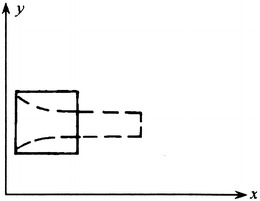
Deformation along x- and y-directions
Turbulence Intensity
Although the magnitude of the fluctuation velocity can be used to describe the strength of the exchange of the fluid particles between layers for indoor air, it is not easy to measure the fluctuation velocity. So it is not convenient to evaluate the turbulent flow with this index. It is hoped that it can be linked with the time averaged velocity.
According to the general monograph about the fluid dynamics, the fluctuation velocity is greatly influenced by the velocity gradient between layers. When the velocity difference between adjacent layers is very large, i.e.,  is large, the driven effect on the current layer is strong, and Δu
x is much larger.
It is supposed that
 |
 |
When they are inserted into Eq. (8.4), the following equation can be obtained:
 |
8.5 |
The item  in the above expression is much smaller. When it is omitted, the above equation can be simplified as [15]
 |
8.6 |
 |
Where l 1, l 2, and l are proportional coefficients which have the dimensions of length. They are also called the mixture lengths. It is a parameter which is proportional to the actual average mixture distance and is also related to the velocity gradient.
It is shown that when the nonuniform extent of the velocity field indoors is reduced, i.e., the velocity gradient between layers is reduced, the fluctuation velocity and fluid particle exchange between layers will be smaller. This is why it is required that the uniform flow in the unidirectional flow cleanroom must be the gradually varied flow at least.
The meaning of the uniform extent of the velocity field is similar as that of the concentration degree of the particle sizes. Therefore, the similar expression can be used, i.e.,
 |
8.7 |
where u
i is the measured velocity at each sampling position. n is the sampling number; when it is less than 30, it can be treated as small sample, so Bessel correction should be made, namely, n is replaced by n − 1.  is the average velocity.
β u can be termed as the turbulibity (or turbidity, nonuniformity of velocity). For unidirectional flow cleanroom, it should not be larger than 0.2, and meanwhile the measured self-purification time is less than 1 min. But practice has shown that it is quite difficult to fulfill this aim. In terms of the self-purification ability, it cannot be larger than 0.25 or even 0.3. If it is too large, the performance of this unidirectional flow cleanroom is rather poor. Other factors should also be referred to evaluate, which will be analyzed in detail in 10.1007/978-3-642-39374-7_10.
In the appendix of American Federal Standard 209B, the uniformity of the velocity field is specified that the local nonuniformity without disturbance should be less than ±20 %. This means all the velocities at every sampling position must be within the range of ±20 % compared with the specified velocity. It is obvious that for the empty room during the acceptance check, there is no disturbance, so the velocity at every place should be within the range of ±20 % compared with the specified velocity. Suppose all the velocities are close to the average velocity except one velocity is larger by 20 %, this velocity field is not qualified according to this specification. It is obvious that the uniformity of the whole velocity field is not considered while only one larger value is considered. In fact, this case will not pose great influence on the usage effect. When the turbulivity is calculated, the value of β u may be smaller than 0.2 or even smaller. It means the flow field is quite uniform. It is shown that it is more appropriate to use the turbulivity at the cross section to evaluate the flow in the unidirectional flow cleanroom. The condition for the comparison of uniformity between velocity fields is also given.
In German Standard DIN 1946-4 published in 2008, one kind of more detailed division method for medical cleanroom was proposed. At the height 1.2 m above the floor, when the turbidity for every sampling point is < 5 % (Comparison is performed with 100 samples taken during 100s when probes are placed horizontally and vertically, respectively.), it is designated as “laminar flow”. The case with the turbidity between 5 % and 20 % is thought as “low turbidity flow”. The case with the turbidity > 20 % is thought as “turbulent flow”. In fact, in German Standard it corresponds to the airflow turbidity at every sampling position (The difference of air velocity at each sampling position within the planar velocity field cannot be reflected). While in this book it means the airflow turbidity of the planar velocity field in the working area (The difference of air velocity at each sampling position within the planar velocity field can be reflected). They are different from each other. In our opinion, it is inappropriate to define the “laminar flow” in the room with the German classification method.
Lower-Limit Velocity [16]
Effect of Flow Velocity in Unidirectional Flow Cleanroom
There are three main reasons for the large construction cost of unidirectional flow cleanroom. Two reasons have been introduced before. The third reason is the large flow rate. As for the flow rate of the unidirectional flow cleanroom, the air change rate reached 400–500 h-1 in early times. The large flow rate is caused by the large velocity at the cross section.
In some standards, the specified velocity is large for the unidirectional flow cleanroom (e.g., in 209B, it is 0.45 m/s), and there’s no difference for the different applications. Some only specifies a value for the velocity, and others suggest a value of the velocity for each kind of cleanroom. This is not convenient for the usage. For example, although the requirement of the air cleanliness for some application is extremely high, when the indoor air is not disturbed since few staff enter in or out according to the process (such as the atom clock in the metering department, which is an equipment with very low heat generation and is placed quietly in the room), or high velocity is not allowed because of the process (e.g., the biological cleanroom for bacterial cultivation and breeding, cleanroom in hospitals), it is inappropriate to design with high velocity. In order to investigate the relationship between the velocity change and air cleanliness in unidirectional flow cleanroom, as well as the allowable lower limit of the velocity, the effect of flow velocity in this kind of cleanroom will be used. Part of the content has been introduced in 10.1007/978-3-642-39374-7_6.
There are mainly four aspects about the effect of flow velocity in unidirectional flow cleanroom:
When polluted air flows in all the directions, the supplied air should control not only the pollution area effectively but also the elevation height and the dispersion distance in the crosswise direction.
When the pollution air flows in the same direction as the supplied air, the supplied air should effectively control the polluted air towards the downstream of the dispersion area.
When the pollution air flows in the opposite direction as the supplied air, the supplied air should control the elevation or advance distance of the polluted air.
When the whole room is polluted, it should take reasonable time for the quick self purification of the room.
When the above four requirements are met, the so-called lower-limit velocity can be obtained.
Pollution Control in All Directions
Pollution in all directions means particles generated from holes emit in all directions, or particles generated from occupant’s movement disperse all around.
The Encompassing Profile of Pollution to Control the Particle Source
The experimental and theoretical analysis has been performed for the encompassing profile of the pollution source in 10.1007/978-3-642-39374-7_6. The semiempirical equation has been obtained. According to the result mentioned in the previous part of this chapter, the pollution at the working height cannot disperse into the region where it is more than 0.5 m from the pollution source. With Eq. (10.1007/978-3-642-39374-7_6#Equ50), the relationship between the ratio of the velocity v of the pollution air to that of the supplied air v ∞ and the radius of the pollution source can be obtained. For the case of θ = 90°, we know:
 |
So we can get:
 |
8.8 |
Therefore the relationship between r and v/v ∞ can be plotted as shown in Fig. 8.37.
Fig. 8.37.
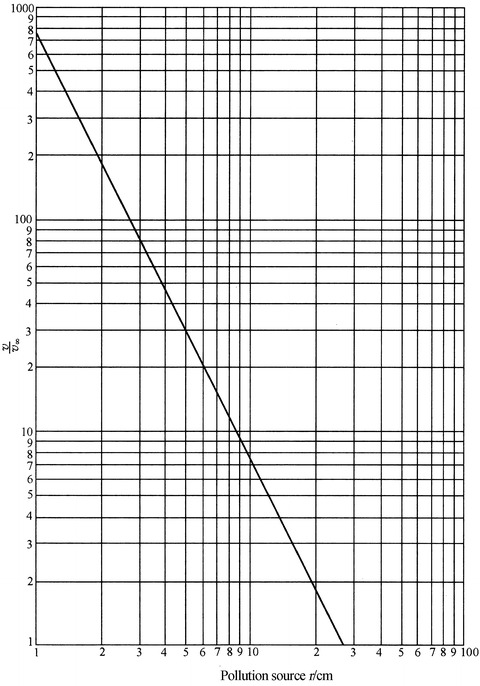
Relationship between the scale of pollution source r and v/v ∞
From the above equation and figure, the trend can be seen that:
The influence of the scale of pollution source on the pollution radius is more than that of the air velocity emitted from the pollution source. So it is the priority to control the scale of pollution source at first during the pollution control process.
When the radius of the pollution source reaches the magnitude of 10 cm, the air velocity which is larger than the polluted air velocity must be adopted. In other words, when the velocity of polluted air is smaller than that of the indoor air, the allowable radius of the pollution source should be larger than 10 cm.
With the same scale of the pollution source, the range of the crosswise pollution mainly depends on v/v ∞. When v ∞ ≥ 0.25 m/s, the radius r of the pollution source can reach 3 cm. The pollution source in all directions with v/v ∞ equals 8.5 is very large.
Influencing Radius of Particle Generation from Occupant
Since occupant’s activities are versatile, which becomes a complex pollution source, it is difficult to find the pollution profile through theoretical analysis and experimental investigation. For the cleanroom, the influencing radius of particle generation from occupant is the concern, which means how far the distance is from the occupant for the pollution to disappear under the supplied air velocity. According to Fig. 8.38, the experiment of this topic was performed [16]. Experimental results are plotted in Fig. 8.39. Squat stand and rotation are the types with the most energy-consumption activities. The particle generation for one activity was measured with 10 times of squatting and standing up or rotation. The particle generation quantity was presented in Table 8.2. Comparison with foreign data was also given. It is shown that the particle generation quantity is large. From the table, when the velocity reaches 0.22 m/s, the pollution concentration at 30 cm from the human body reduces to 1 pc/L, which is much lower than the upper limit of concentration for Class 100 cleanroom.
Fig. 8.38.
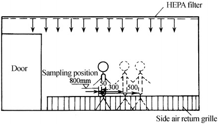
Influencing radius of particle generation from occupant
Fig. 8.39.
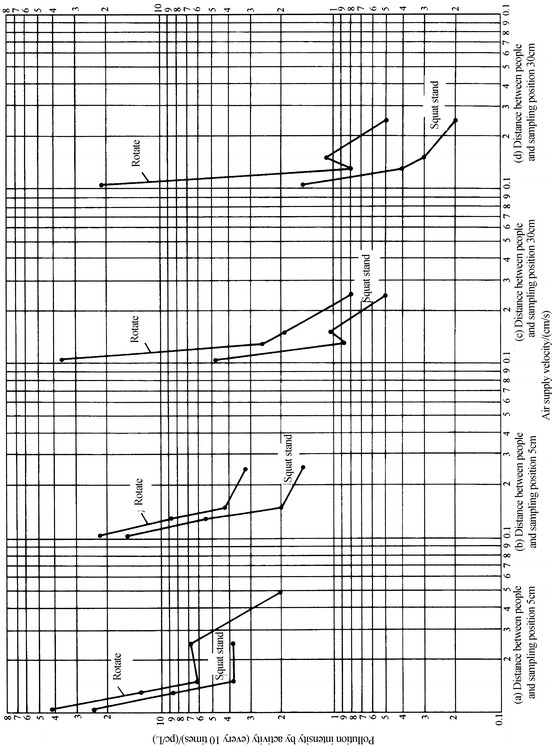
Influencing radius of particle generation with different types of activities
Table 8.2.
Particle generation for different activities
| Particle size (μm) | Particle number [pc/(p · mm)] | Working cloth | Activity intensity | Ref. |
|---|---|---|---|---|
| ≥0.5 | 2 × 10⁶–3 × 10⁷ | Perform gymnastic activity | [17] | |
| 0.63 × 10⁶ | Head move around | |||
| 0.85 × 10⁶ | Upper body movement | |||
| 2.7 × 10⁶ | Clean working garment | Bend body | [18] | |
| 2.8 × 10⁶ | March on the spot | |||
| (0.25–0.5) × 106 | Walk with average velocity 0.8 m/s | [19] | ||
| 0.27 × 10⁶ | Walk with velocity 110 steps/min | [20] | ||
| 2.6 × 10⁶ | Fabric working garment | Walk with velocity 110 steps/min | ||
| (0.7–3) × 106 | Clean working garment | Squat, stand, or rotate | [16] | |
| ≥0.3 | 5 × 10⁶ | Walk with velocity: 3.6 km/h | ||
| 7.5 × 10⁶ | Clean working garment | 5.6 km/h | [21] | |
| 10 × 106 | 8.8 km/h |
Pollution Control with the Same Direction
Air should be supplied with enough velocity, so that the pollution upstream can be driven to the downstream quickly, which will not disperse outside of the allowable range. Figure 8.40 shows the experimental results [16]. As proposed in the section about the parallel degree of fluid lines, the requirement of the crosswise distance of the fluid lines downstream is that pollution generated at the height of 1.8 m disappears at the downstream height of 0.75 m. The relationship between the distance from the projected position of the pollution source and the air velocity is given. This distance is termed as the furthest pollution boundary. The distance of 0.5 m is called the limit pollution boundary. It is shown that when the furthest pollution boundary is located in the limit pollution boundary, the air supply velocity should not be less than 0.3 m/s.
Fig. 8.40.
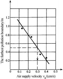
Relationship between the crosswise pollution distance downstream and velocity
Pollution Control with the Opposite Directions
For Vertically Unidirectional Flow Cleanroom
The main pollution with opposite directions in vertically unidirectional flow cleanroom is the flow aroused from the heat source. As illustrated in 10.1007/978-3-642-39374-7_6, for the vertically unidirectional flow cleanroom with heat source inside, the necessary air supply velocity should be determined with the parameters of heat source. Or the parameters of heat source should be limited with the given air supply velocity. Or strict measures should be adopted to isolate the heat. Table 8.3 presents the relationship between velocity and parameters of heat source. In the table, l is the characteristic length of the heat object, and R y is the equivalent radius of the planar heat source.
Table 8.3.
Relationship between velocity and parameters of heat source
| △t (°C) | Air supply velocity (m/s) | |||||||||||
|---|---|---|---|---|---|---|---|---|---|---|---|---|
| 0.2 | 0.25 | 0.3 | 0.35 | 0.4 | 0.5 | |||||||
| l (m) | R y (m) | l (m) | R y (m) | l (m) | R y (m) | l (m) | R y (m) | l (m) | R y (m) | l (m) | R y (m) | |
| 10 | 0.24 | 1 | 0.38 | 2 | 0.54 | 3.4 | 0.735 | 5.4 | 0.96 | 8.1 | 1.5 | 11.5 |
| 30 | 0.08 | 0.23 | 0.125 | 0.46 | 0.18 | 0.78 | 0.245 | 1.25 | 0.32 | 1.87 | 0.5 | 2.7 |
| 50 | 0.05 | 0.11 | 0.08 | 0.23 | 0.113 | 0.4 | 0.153 | 0.63 | 0.2 | 0.95 | 0.313 | 1.3 |
| 70 | 0.035 | 0.08 | 0.055 | 0.15 | 0.079 | 0.27 | 0.107 | 0.40 | 0.14 | 0.60 | 0.22 | 0.86 |
| 100 | 0.024 | 0.05 | 0.04 | 0.1 | 0.054 | 0.16 | 0.073 | 0.25 | 0.096 | 0.40 | 0.15 | 0.53 |
| 150 | 0.017 | 0.03 | 0.027 | 0.06 | 0.037 | 0.1 | 0.05 | 0.15 | 0.067 | 0.22 | 0.104 | 0.37 |
| 200 | 0.012 | 0.02 | 0.019 | 0.04 | 0.027 | 0.07 | 0.037 | 0.10 | 0.048 | 0.15 | 0.075 | 0.21 |
For Horizontally Unidirectional Flow Cleanroom
The main pollution flow with opposite directions of the horizontally unidirectional flow cleanroom is the secondary flow caused by occupant’s walk. As for the magnitude of the secondary flow, it has been illustrated in detail in 10.1007/978-3-642-39374-7_6, which will not be repeated again.
Reasonable Self-Purification Time
When all the room is polluted, indoor air should be self-purified rapidly within a reasonable time period, which is greatly related to the air velocity in the cleanroom. With the increased flow velocity, the self-purification ability is stronger and the self-purification time is short, but it is not economical. Therefore, the lower limit of velocity should be determined, with which the shortest self-purification time can be guaranteed. Figure 8.41 presents the relationship between the self-purification time and velocity performed abroad and by the author.
Fig. 8.41.
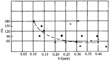
Relationship between self-purification time and velocity: Δ vertically unidirectional flow cleanroom with grille floor [6], × measured data of the cleanroom. ○ domestic assembled vertically unidirectional flow cleanroom with full air supply at the ceiling and air return at both bottom sides (authenticated data), ● vertically unidirectional flow cleanroom with full air supply at the ceiling and air return at one bottom side
It is shown that when the velocity is larger than 0.25 m/s, the self-purification time almost remains the same, which is about 1 min. The effect of increased velocity on shortening the self-purification time is not obvious. Therefore, it is advisable to choose the lower limit of velocity 0.25 m/s corresponding to the shortest self-purification time. As for the self-purification time of the cleanroom, it will be illustrated in detail in 10.1007/978-3-642-39374-7_10.
Comprehensive Analysis
The difference of the velocity needed to consider the above four aspects is small, which are listed in Table 8.4. According to the comprehensive conditions and the abovementioned viewpoint, it is suitable to divide the lower limit of velocity into three categories for vertically and horizontally unidirectional flow cleanroom, which are listed in Table 8.5.
Table 8.4.
Velocity needed to control pollution [15]
| Pollution control type | Air velocity (m/s) and situation |
|---|---|
| Pollution from multiple directions | |
| Envelope line of pollution generation | ≥0.25 (this is common for ordinary pollution source) |
| Radius of pollution generation from people | ≥0.22 |
| Pollution from the same direction | ≥0.3 |
| Pollution from opposite directions | |
| 1. For vertical unidirectional flow cleanroom | |
| Heat source | Generally determined by the size and the temperature of heat source (e.g., it is 0.64 for the heat plane with surface temperature 200 °C and size 0.3 m × 0.6 m) |
| Thermal plume from people | 0.18–0.22 |
| 2. For horizontal unidirectional flow cleanroom | ≥0.34 (the ordinary walk velocity is 1 m/s, and the maximum velocity of secondary air is considered) |
| ≥0.28 (the ordinary walk velocity is 1 m/s, and the average velocity of secondary air is considered) | |
| ≥0.4 (the walk velocity is about 1.5 m/s) | |
| ≥0.5 (the walk velocity is about 2 m/s) | |
| Self-cleaning ability | ≥0.25 |
Table 8.5.
Suggested lower limit of velocity [16]
| Cleanroom | Lower limit of air velocity (m/s) | Condition |
|---|---|---|
| Vertical unidirectional flow | 0.12 | No occupant during ordinary times or rare pass in and out, no obvious heat source |
| 0.3 | With the general condition without obvious heat source | |
| ≯0.5 | With occupant inside and obvious heat source. If it is still not feasible to set 0.5, the size of the heat source should be controlled, and isolation measures should be taken | |
| Horizontal unidirectional flow | 0.3 | No occupant during ordinary times or rare pass in and out |
| 0.35 | General condition | |
| ≯0.5 | With higher requirement or frequent pass in and out |
It is clear that the lower limit of velocity means the minimum velocity that cleanroom should always keep. During the design process, the increased pressure drop caused by air filter should be considered. The flow rate will be reduced. So this will be used to determine the initial velocity, and it should be adjustable for the flow rate.
It should be mentioned that the data in the middle is usually fit for most cleanrooms. When there is not occupant or activity, the lower limit of velocity can be used, such as the night situation of ward and the equipment monitoring room without entering in and out. Experiment has been performed in the control room of the atom clock, it was found that with the velocity 0.11 m/s, the requirement is met when twice and three times of instrument check every day is done. The upper bound of the lower limit of velocity should be 0.5 m/s; otherwise, the draught effect will be felt.
The average velocity suggested for unidirectional flow cleanroom in ISO14644-4 in 2000 is: 0.2–0.5 m/s for Class 5 (equivalent with Class 100) and 0.3–0.5 m/s for higher than Class 5. This is the first breakthrough of the specification ≮0.45 m/s in American Federal Standard 209. But the exact condition for choosing the value is not given. They are all within the theoretical range of lower limit of velocity shown in Tables 8.4 and 8.5.
Principle of Radial Flow Cleanroom
Type of Radial Flow Cleanroom
Radial flow cleanroom appeared later than turbulent flow cleanroom and unidirectional flow cleanroom. It is a novel type of cleanroom with the significance of energy saving. It has application abroad, but it is almost blank in China.
This kind of cleanroom was ever termed as “arrow flow cleanroom.” However, the concept of “arrow” cannot completely represent the meaning of the radial streamline. Since any streamline can be called “arrow,” author calls it as “radial flow cleanroom” [22].
The type of radial flow cleanroom is shown in Fig. 8.42, where fan-shaped, semispherical, or semicylinder air supplier combined with corresponding type of HEPA filter is used to supply air at the top side of the room and air is returned at the opposite bottom side (Fig. 8.43).
Fig. 8.42.
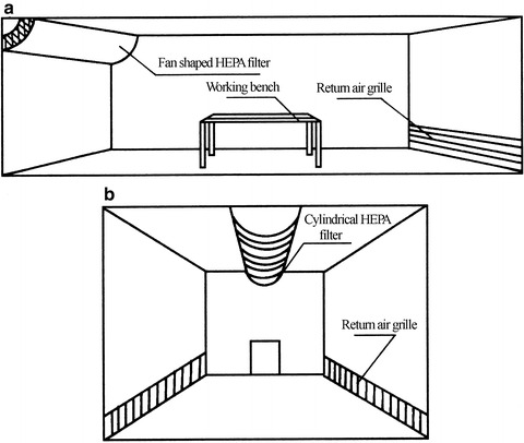
Schematic of radial flow cleanroom. (a) Fan shaped air supply outlet. (b) Cylindrical air supply outlet
Fig. 8.43.
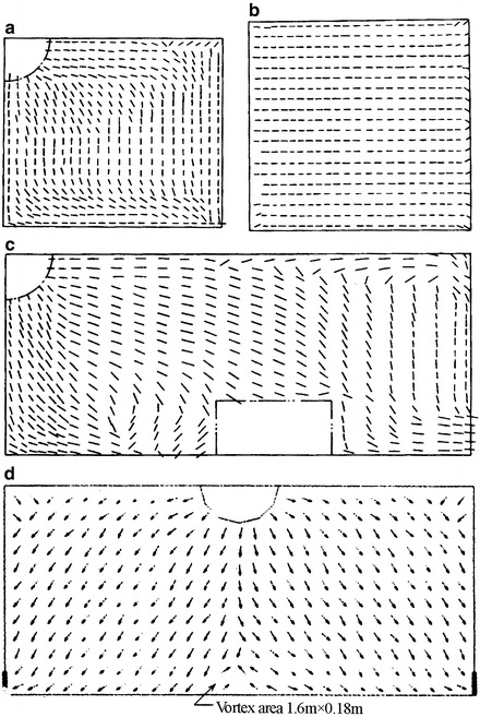
Calculated flow field of radial flow cleanroom. (a) Profile of as-built room. (b) Horizontal profile of as-built room. (c) Profile of at rest room (with fan shaped air supply outlet). (d) Profile of as-built room (with fan shaped air supply outlet)
Principle of Radial Flow Cleanroom
Fundamental Principle
The principle of radial flow cleanroom is different from the mixture and dilution effect of turbulent flow cleanroom and also different from the “piston” flow of unidirectional flow cleanroom. The streamlines are neither unidirectional nor parallel. This is the same as the turbulent flow cleanroom. But the difference with the turbulent flow cleanroom is that streamlines do not intersect. So it is not the mixture effect, but the squeezing effect with “inclined push” instead of “flat push” that works in this kind of cleanroom.
Feature of the Flow Field
A study about this kind of cleanroom has been reported in China [23–25]. Calculated and experimental flow fields in the above literatures are presented in Figs. 8.34 and 8.44.
Fig. 8.44.
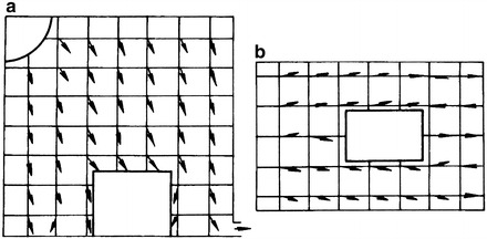
Experimental flow field of radial flow cleanroom with fan-shaped air supplier. (a) Profile of at rest room. (b) Vertical profile of at rest room
Feature of the Concentration Field
With the method of smoke release ball at the working area, the experimental data about the concentration field in radial flow cleanroom with fan-shaped air supplier were obtained, which is shown in Fig. 8.45 [24]. The air change rate with circulated air in cleanroom is  . The velocity of polluted air v = 1.5 m/s. The flow rate is 16 L/min. The pollution source is a Balan cigarette.
Fig. 8.45.
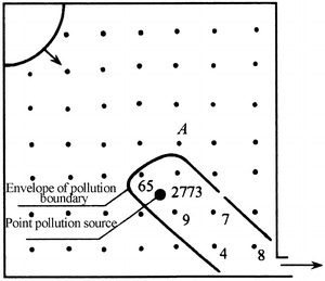
Measured concentration field in as-built radial cleanroom
The numerical simulation of the concentration field is presented in Fig. 8.46 [24]. In the figure, “1” presents the concentration of particles with diameter ≥0.5 μm less than 1 pc/L. “2” represents the concentration less than 3.5 pc/L. “3” represents the concentration ≥3.5 pc/L. The trend of concentration distribution is almost consistent with experimental result.
Fig. 8.46.
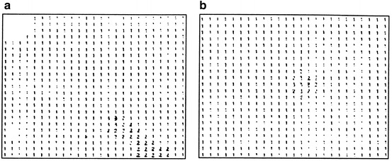
Calculated concentration field in radial flow cleanroom. (a) Profile of as-built room. (b) Horizontal profile of as-built room
Basic Features
From the comparison between calculated and experimental result in the above literature, the radial cleanroom is thought to have the following features:
The streamlines do not intersect in the as-built situation. The lateral diffusion between streamlines is very weak. At the upper corner of the downwind side, there is a very weak backflow, which will not influence the exhaust of polluted flow to downwind. Although the detention time of pollution is longer than that of unidirectional flow cleanroom, it is shorter than the self-purification time of turbulent flow cleanroom, which meets the requirement for the feature of cleanroom which can exhaust the polluted flow in a comparatively short or even the shortest route.
In the status of at-rest, eddy appears on the downwind side or two sides of the obstacle. So in this kind of cleanroom, obstacles should be avoided along the streamline. For example, the bottom of the table shown in Fig. 8.44 should be perforated.
In the cleanroom with fan-shaped air supplier, the influence of return air grille on the flow field and concentration field is very small. In the cleanroom with semicylinder air supplier, return air grille installed at low position is good for pollution control. The height of return air grille is usually 0.3 m.
The appropriate design parameters for radial flow cleanroom were proposed by experimental result:
For fan-shaped air supplier,
 |
For semicylinder air supplier,
 (room width should be between 6 and 12 m)
 |
 |
 |
 |
 |
 |
In short, although the air distribution in radial flow cleanroom is not uniform as that in unidirectional flow cleanroom, both air supplier and air filter are much complex than the common case, and eddy is easily formed in the status which is not as-built. The construction cost is much lower than that of unidirectional flow cleanroom. The surface cleanliness level can reach Class 100. So this is one kind of cleanroom worthwhile for attention.
Pressure of Cleanroom
In order to prevent the cleanliness of cleanroom from the contamination by adjacent room, the pressure of the cleanroom is maintained to a value which is higher or lower than adjacent room. This is the important feature of cleanroom which is different from ordinary air-conditioning room. This is also the important component for the principle of cleanroom. It is usual to set a positive differential pressure (abbreviated as “positive pressure” in the following section) between cleanroom and the adjacent environment, which is the situation for industrial cleanroom and ordinary biological cleanroom. Negative differential pressure is only maintained in special biological cleanroom (abbreviated as “negative pressure” in the following section).
Physical Meaning of Differential Pressure
When doors, windows, and any kinds of pore exist between cleanroom and adjacent space, a relative positive pressure should be kept between them when these doors, windows, and pores are closed. The value of differential pressure corresponds to the resistance of the air flowing through the closed aperture with a certain amount of flow rate. So the differential pressure reflects the resistance characteristic of the aperture.
Suppose pressures at both sides the aperture are P 1 and P 2, respectively. The differential pressure according to the hydrodynamics theory is:
 |
8.9 |
where
h w is the frictional resistance for air flowing through the aperture. Since the aperture is very short, and v c is usually smaller than 4 m/s with the usual differential pressure in the cleanroom, h w can be neglected.
ξ 1 is the local resistance of abrupt contraction. Since the cross-sectional area of the aperture is extreme small, ξ 1 ≈ 0.5.
ξ 2 is the local resistance of abrupt expansion. With the same reason, ξ 2 ≈ 1.
Therefore
 |
8.10 |
 |
A study by author has shown the actual value of φ is usually between 0.2 and 0.5 [26].
The relationship between the flow rate and the resistance through the aperture is:
 |
8.11 |
where
ε is the contraction coefficient;
μ is the flow rate coefficient, and it is usually 0.3–0.5.
If the aperture structure is very complex, the above proportional relationship between Q and the square of ΔP is no longer valid; instead, Q is linearly proportional to 1–1/2 order of ΔP. But the above calculation expression can also be used for the aperture of cleanroom since the surface is very flat and the aperture is not complex.
Since the differential pressure reflects the resistance feature of aperture relative to the region outside of the room, the resistance will disappear when the aperture is open, so the differential pressure will disappear accordingly. So the differential pressure appears and plays its role only when the door is closed.
Figure 8.47 shows the time characteristic of the differential pressure [37].
Fig. 8.47.
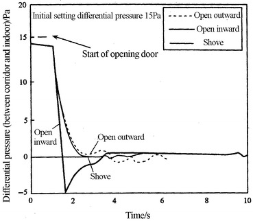
Variation of differential pressure with time during opening of door
Function of Differential Pressure
The general function of differential pressure has been introduced in the beginning of this section. From the theoretical point of view, there are two functions for differential pressure:
With the closed door and window, it can prevent the infiltration of pollution outside of the cleanroom into the room.
At the moment of opening the door, it can provide enough air flowing outwards. The amount of airflow entering the room by the opening of door and the entering of the occupant should be reduced as much as possible. When the door is open, the direction of airflow should be guaranteed to be outwards, so that the pollution generated can be minimized.
As for item (1), it does not mean the larger the differential pressure is, the stronger the ability to prevent the pollution infiltration is. It is known from Eq. (8.10) that in theory the differential pressure 0.22 Pa is enough, which can generate the air velocity 0.5 m/s at the aperture. A study performed by author has shown that the variation of blockage effect is relatively large when the differential pressure changes from 0 to 6 Pa while it is relatively small when the differential pressure varies from 6 to 30 Pa, which is shown in Fig. 8.48.
Fig. 8.48.
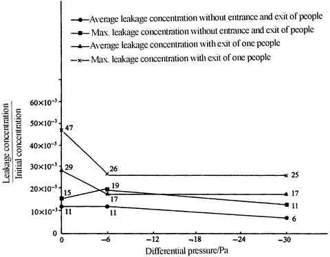
Relationship between the concentration of leakage and the differential pressure
Figure 8.49 presents the data from Japan [27]. When the differential pressure increases from 0 to 6 Pa, the dispersion amount of particles reduces by about 40 %. But it only reduces by 60 % when the differential pressure increases from 0 to 30 Pa.
Fig. 8.49.
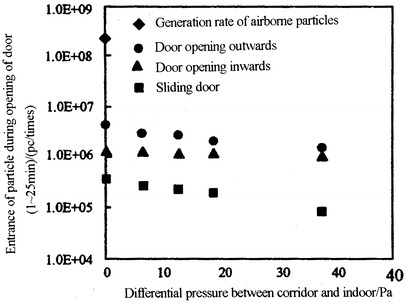
Number of particles entering into the negative pressure cleanroom with the closed door
The above results are basically consistent.
As for item (2), in the initial standard about cleanroom, i.e., American Air Force Design Manual (AD295408, TDR-62-138 Report) and US Federal Standard 209A, only the second item was mentioned. From the calculation introduced later, we can see that it is difficult to realize the second item. Therefore, since the beginning of 209B, the first item was made as the compulsory one, while the second item was optional and used for guidance. It is the same for NASA NHB 5340-2. In British Standard BS5295(I), only the first item was mentioned. Experiment has shown that the second item is very important for the cleanroom with cleanliness Class 100 or higher. So in the standard “Test and Acceptance Evaluation of Industrial Cleanroom” (AACC CS-6 T) published by American Association of Contamination Control and other standards published by some companies, except for the requirement of differential pressure between inside and outside of the cleanroom when the door is closed, the upper limit of particle concentration at 60 cm away from the door in the cleanroom with air cleanliness Class 5 or lower was specified. It is aimed to prove that the invasion flow from outside of the room is extreme small and the invasion flow is resisted by the external flow. The requirement of this item is not so strict in Chinese Industrial Standard GB50591-2010 Code for construction and acceptance of cleanroom. This is the compulsory standard for cleanroom with air cleanliness Class 5 or higher. The effect of differential pressure is not clearly presented in related standards and regulations in China before this standard. But in national standard GB 50591 implemented since 2010, this is required for cleanroom with air cleanliness Class 5 or higher.
Determination of Differential Pressure to Prevent Leakage from Gap Between Cleanroom and Adjacent Room
From Eq. (8.10), the velocity can be 1.06 m/s when the positive pressure between cleanroom and the adjacent room is ΔP = 1 Pa. This air velocity with this magnitude can prevent the infiltration of air flowing through the aperture. Of course 1 Pa is an extreme small value and not stable. For two rooms connecting with each other, their pressures will vary with waxing and waning effect for the differential pressure with 1 Pa. When the fresh air varies with the volume corresponding to the need of one people, i.e., dozens cubic per hour, the change of differential pressure will be larger than 2 Pa. This easily occurs because of the untimely adjustment of air filter and valve. So the differential pressure needed for the room should be a little larger. In those countries (such as China and Japan) where the metric system was used in the past, mmHg was used to express the differential pressure. So the minimum unit, namely, the half of 1 mm H2O (5 Pa), is the minimum readable value. It is 5 times larger than 1. So 5 Pa is habitually used as the necessary value of differential pressure. In those countries (such as the UK and USA) where the imperial system of unit was used, inch H2O was used to express the differential pressure. So the minimum unit, namely, the half of 0.1 in. H2O (1.27 mm H2O, 12.4 Pa), is the minimum readable value. So 0.05 in. H2O is habitually used as the necessary value of differential pressure.
Determination of Differential Pressure to Prevent Leakage from Gap Between Cleanroom and Outdoor (or the Room Open to the Atmosphere)
Among all kinds of the apertures and pores connected to atmosphere, apertures, doors, and windows are the most common. Even for the sealed windows, infiltration will occur under the effect of wind pressure if the indoor pressure is negative. When air flow is perpendicular to the building envelop, positive pressure will be formed at the weather side and negative pressure at the lee side, which is shown in Fig. 8.50. The pressure at the weather side is:
 |
8.12 |
where
u is the calculated infiltration velocity at the weather side (m/s);
ρ is the air density, and at normal temperature it is 1.2 kg/m3;
C is the wind pressure coefficient, which can be set 0.9 on average.
Fig. 8.50.
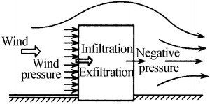
Pressure on the wall by wind
Calculated infiltration velocity at the weather side is related to many factors, including air velocity at the weather side, building shape, layer height, orientation, and temperature difference. If the assurance rate is set larger than 90 %, it can be calculated by equation. Table 8.6 shows the calculated air velocity at various orientations in ten Chinese cities [28]. The trend is that it is the strongest in the region near the ocean. It is in the middle for cities in eastern area. It is weak in cities like Xian and Urumqi.
Table 8.6.
Calculated air velocity at various orientations in ten Chinese cities
| City | N | NW | W | SW | S | SE | E | NE | Partition of air velocity regions |
|---|---|---|---|---|---|---|---|---|---|
| Urumqi | 1.0 | 0.9 | 0.3 | 0.3 | 0.6 | 0.3 | 0.3 | 0.3 | I, weak |
| Xi’an | 0.8 | 0.3 | 0.3 | 0.7 | 0.7 | 0.3 | 0.3 | 1.0 | |
| Hohhot | 1.8 | 2.8 | 1.1 | 0.3 | 0.3 | 0.3 | 0.3 | 0.3 | II, intermediate |
| Shenyang | 3.6 | 2.5 | 0.3 | 0.3 | 1.5 | 0.3 | 0.3 | 2.0 | |
| Tianjin | 3.8 | 3.8 | 1.5 | 0.3 | 0.3 | 0.3 | 0.3 | 1.8 | |
| Zhangjiakou | 4.0 | 4.0 | 1.2 | 0.3 | 0.3 | 0.3 | 0.3 | 1.4 | |
| Beijing | 4.5 | 4.2 | 1.4 | 0.3 | 0.3 | 0.3 | 0.3 | 2.7 | |
| Harbin | 2.2 | 4.1 | 4.7 | 5.2 | 4.9 | 2.5 | 0.3 | 0.3 | |
| Dalian | 6.6 | 5.6 | 3.0 | 3.4 | 3.4 | 0.9 | 0.3 | 5.0 | III, strong |
| Qingdao | 7.0 | 7.0 | 4.5 | 2.9 | 3.6 | 3.4 | 2.0 | 4.7 |
If the middle zone is selected, the maximum air velocity can be set 5 m/s, so ΔP =14 Pa, which is larger than the value 10 Pa specified in current standard by 40 %. If it is much stricter, 6 m/s can be used as the calculation basis, so ΔP = 20 Pa. Of course, this is not the strictest situation.
Determination of Differential Pressure to Prevent Air Pollution During the Open of Door in Turbulent Flow Cleanroom
When people enter Cleanroom B from Cleanroom A (shown in Fig. 8.51), it was measured that at the moment people enter the room along the direction of door, the air velocity generated at the entrance is within the range 0.14–0.2 m/s.
Fig. 8.51.
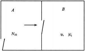
Situation of occupant’s entrance into cleanroom with the open door
At the moment people enter the room against the direction of door, the air velocity generated at the entrance is within the range 0.08–0.15 m/s, which is smaller than the previous situation. From measurement, it is found that only when people enter the room and the door is open, the air velocity reaches the maximum, and it lasted for 2 s.
The flow rate by the entrance of people into the room is:
 |
Next two situations will be discussed:
When the particle concentration of the entrance flow is 10 times higher than N which is inside the room, namely, it corresponds to the air cleanliness lower by 1 level, and the unfavorable volume V of the cleanroom is assumed 25 m3 (the less it is, the more disadvantage it will be).
Suppose two people enter the room, the increased ratio of indoor particle concentration by the entrance flow is (here the particle generation from people is not considered, which is needed for the design of cleanroom; transient self-purification of indoor air circulation is also not considered):
 |
This means the indoor particle concentration increases by 1.19 times instantaneously because of the entrance of two people. Since normal concentration indoors N should be less than the upper limit of concentration corresponding to the related air cleanliness, 1/3–1/2 of this value is used during the design process (refer to 10.1007/978-3-642-39374-7_13 about the design calculation). The cleanroom is operated in the limit of 2/3, i.e., 0.7 N, for most of the time. So there is an ascensional range for the allowable concentration less than N. It is appropriate to set this range 0.2 N, which means the increase of instantaneous value can be not larger than 1.2 N. The larger the cleanroom volume is, the less the increase of the ascensional range will be.
So when people enter room B from room A, where the air cleanliness of Room A is one class lower than that of Room B, the disturbance of entrance does not pose any threat for the air cleanliness of Room B, and self-purification will complete within several minutes. The detailed information is shown in 10.1007/978-3-642-39374-7_10#Sec10.
-
2.
When the particle concentration of the entrance flow is 100 times higher than N which is inside the room, namely, it corresponds to the air cleanliness lower by 2 levels, and the volume V of the cleanroom is assumed 25 m3, so we know:
 |
This means the indoor particle concentration increases by 3.14 times instantaneously at most.
If the limit to surpass the corresponding concentration is set 1.2 N, the following expression can be written:
 |
 |
When ΔV = 0.27 is inserted, we can obtain V ≥ 267 m3.
This means when the volume of the cleanroom is larger than 270 m3, the concentration can be increased instantaneously by 1.2 times at most when two people enter in.
Let V = 25 m3, the allowable air velocity intruding into the cleanroom can be obtained as follows:
 |
So
 |
So the squeezing velocity from the cleanroom is:
 |
When it is the single-leaf door, and the open area is 1.5 m2, the flow rate of positive pressure needed is:
 |
It is quite difficult for the small room with volume 25 m3. So other measures are needed, which is shown in Sect. 8.8 about the buffer chamber.
If ΔV = 75 m3, we can obtain n = 0.08 m/s, which corresponds to the flow rate with positive pressure 432 m3/h.
The flow rate Q with positive pressure can be calculated with the following expression:
 |
8.13 |
where
α 1 is the safety coefficient and the suggested value is 1.2;
α 2 is the coefficient when both the door aperture and other apertures, and the suggested value is 1.2;
q is the leakage flow rate per unit length through non-seal door [m3/(h · m)], and it can be found in Table 8.7 [29];
l is the aperture length of non-seal door (m). For single-leaf door, it is 6 m.
Table 8.7.
Leakage flow rate through non-seal door
| Differential pressure (Pa) | 4.9 | 9.8 | 14.7 | 19.6 | 24.5 | 29.4 | 34.3 | 39.2 | 44.1 | 49 |
| q [m3/(h∙m)] | 17 | 24 | 30 | 36 | 40 | 44 | 48 | 52 | 55 | 60 |
It is calculated that only when the differential pressure is 39.2 Pa (4 mm H2O), the flow rate with positive pressure can be 449 m3/h. When the requirement of 432 m3/h is satisfied, the air change rate of the flow rate with positive pressure is equivalent to 6 h−1, which is the flow rate of fresh air (this value is usually not surpassed for other applications for the requirement of the fresh air).
If the aperture is very small, with the requirement of relative large flow rate during the process of opening the door, the differential pressure needed should be above 40 Pa, which will influence the process of opening the door and generate noise easily. So in terms of this aspect, except the strict requirement for the sealing of other places, the requirement for the door is not necessarily strict. For example, there is a certain aperture between the door and the floor, which is easy for the manufacture and open of the door but also for prevention of the particle generation because of the friction by the sealing strip. It can also adapt to the comparatively large flow rate with positive pressure under the specified differential pressure, so that part of the invasion flow can be offset. If the calculated flow rate with positive pressure through the aperture is not enough, the flow rate can be increased and the excess pressure damper can be installed. The excess pressure damper is used to exhaust the superfluous flow rate. The room pressure decreases once the door is open, then the excess pressure damper turns small automatically. The pressurized air flows outwards with the required velocity to offset the invasion-polluted flow rate.
There is another opinion for this aspect, which requires the door to be very sealed (actually it is hard to be realized). The method of constant exhaust system is adopted. Most flow rate of the positively pressurized air is exhausted when the door is closed. When the door is open, most positively pressurized air is still exhausted, and the available flow rate outwards is extreme less, which cannot meet the requirement of the second item about the differential pressure. So this method cannot completely solve the pollution problem from outside (suppose this pollution exists). If necessary, the buffer chamber should be placed, which will be analyzed in detail later. If it is not allows for the indoor air flowing outwards, the cleanroom should be designed as negative pressurized.
Determination of Differential Pressure to Prevent Air Pollution During the Open of Door in Unidirectional Flow Cleanroom
The ability of anti-disturbance is extremely strong for the unidirectional flow cleanroom, since the self-purification time is extremely short (analyzed in detail later). The pollution brought by the invasion flow during the opening of the door will be exhausted by the unidirectional flow quickly, and it is impossible to exchange the air transversely. So this problem should not be considered during the determination of the differential pressure.
But according to the requirement of Code for construction and acceptance of cleanroom (GB 50591-2010) for cleanroom with air cleanliness Class 5 or higher, the indoor air cleanliness level at 0.6 m from the door during the opening of the door should not be lower than the corresponding air cleanliness level with the negative pressure. This means the pressurized air should prevent the instantaneous invasion flow from entering into the place 0.6 m from the door, which is shown in Fig. 8.52.
Fig. 8.52.
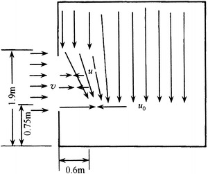
Allowable depth of invasion flow through the door hole
When the lower velocity 0.3 m/s is set for the indoor air velocity u 0, and the door height is assume 1.9 m, we can get:
 |
So we obtain:
 |
This means the allowable air velocity of invasion flow should be less than 0.16 m/s. When the air velocity caused by the entrance of people is assumed 0.2 m/s as mentioned before, the air velocity needed to push outwards should be:
 |
With the same parameters as the above case, the pressurized flow rate should be larger than 216 m3/h, and ΔP should be larger than 10 Pa.
Recommended Differential Pressure
Combined with the analysis in above sections, the recommended differential pressure is proposed, which is shown in Table 8.8.
Table 8.8.
Recommended differential pressure
| Purpose | Difference between turbulent flow cleanroom and the adjacent room with air cleanliness level lower by one Class level (Pa) | The same as the left condition but with air cleanliness level lower by more than one Class level (Pa) | Difference between unidirectional flow cleanroom and the adjacent communicating room (Pa) | Difference between cleanroom and outdoors (or the space communicating with outdoor air) | |
|---|---|---|---|---|---|
| General | To prevent infiltration through gap | 5 | 5–10 | 5–10 | 15 |
| Strict | To prevent entrance of pollution during door opening | 5 | 40 or it is 5 relative to buffer chamber | 10 or it is 5 relative to buffer chamber | It is 10 relative to buffer chamber |
| Sterile cleanroom | 5 | It is 5 relative to buffer chamber | It is 5 relative to buffer chamber | It is 10 relative to buffer chamber | |
The detailed information about the calculation method for the fresh air and exhaust airflow rates with the requirement of positive and negative pressure is illustrated in other monograph [22].
Buffer and Isolation
The purpose of the pressure kept in the cleanroom is to prevent the entrance of pollution into the cleanroom. But sometimes it is too large to be realized. The auxiliary measures should be taken, including setting the buffer chamber, the airlock chamber, the air curtain chamber, and the airshower chamber. All these measures aim to reduce the entrance of the pollution into the room or reduce the generation of pollution indoors.
Airlock Chamber
It is the Technology Regulations T.O.00-25-203 published by US Air Force that first proposed the airlock chamber which has the buffer effect. “Airlock chamber is the small room at the entrance of the cleanroom. There are several doors in the airlock chamber, and only one door can be open at the same time. The purpose is to prevent the external pollution from entering into the cleanroom and to play the role of sealing.” Other standards in America later and the Good Manufacture Practice (GMP) from WHO have the same definition.
WHO proposed that “the airlock chamber means the sealed space with two doors, which is placed between two or several rooms, such as the rooms with different air cleanliness levels. The purpose is to control the air flow between rooms with airlock chamber when people enter in or out of these rooms. The airlock chamber should be designed for people or goods.” It is obvious that the airlock chamber is only the room where doors are interlocked and cannot be opened at the same time. Although the air change rate was required in some literatures, for example, in NASA NHB5340-2 it was proposed that “enough ventilation and air exchange should be provided in the airlock chamber”; the supplied air was required to be clean in some literatures, the air cleanliness level is not clearly presented. The room without supplying clean air can act as the buffer at most. However, this kind of buffer cannot effectively prevent the invasion of outside pollutants. Because when people enter this airlock chamber, the dirty air from ambient enters into the chamber. When the other door is opened, the already polluted air in the chamber will enter the cleanroom. This has been illustrated in the previous sections.
In the literature from Japan [30], the airlock chamber was also translated into the antechamber, which has the implication of preparation room and is shown in Fig. 8.53. Although the air cleanliness level is not specified, it is suggested to supply clean air. It should be negatively pressurized relative to the cleanroom and positively pressurized relative to the ambient.
Fig. 8.53.
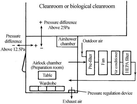
Setting of the airlock chamber in Japan
British Standard BS5295 I has also pointed out that “airlock chamber can be used as the antechamber.”
The implication of airlock chamber is inconsistent in China. One adopted the definition from the Technology Regulations T.O.00-25-203 published by US Air Force. The other considered the airlock chamber as the small room with air curtain at the entrance of the cleanroom, which is illustrated in Fig. 8.54.
Fig. 8.54.
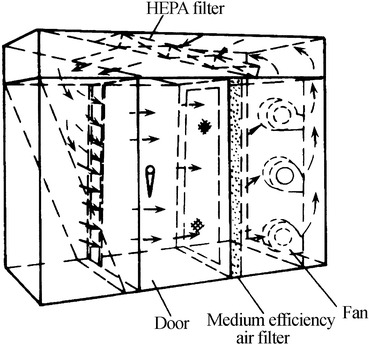
Airlock chamber with air curtain
The above airlock chamber with air curtain is called air curtain equipment. Doors in this kind of air curtain chamber do not need to be interlocked. It is the air curtain that seals the door hole. There can be one air curtain or two air curtains, which is shown in Fig. 8.55.
Fig. 8.55.
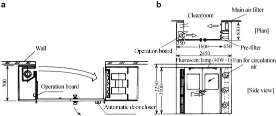
Air curtain equipment in Japan. (a) One air curtain. (b) Two air curtains
At present, the term of airlock chamber used in America is not appropriate. But since it has been popular, it is not good to change the term. The airlock chamber with air curtain in domestic area can be called airlock chamber with air curtain, while the air curtain equipment without door interlock in Japan can be called air curtain chamber. This will help people distinguish between the two situations.
Buffer Chamber with Positive Pressure
From the analysis in the above section, only when the volume of the cleanroom is less than 270 m3, the buffer chamber should be installed at the entrance, so that the pollution caused by the entrance and exit of the people can be controlled. When polluted particles are the same kind and it is allowable for the self-purification time larger than 2 min, the buffer chamber is not needed. But when cross infection occurs and the damage caused is very serious, it should be placed even for two adjacent cleanrooms with the same air cleanliness level.
It is shown in Fig. 8.56 that when a buffer chamber is placed between two cleanrooms with two levels of air cleanliness difference (N 1 and N 100), its air cleanliness level should be the same as that of the higher level (N 1).
Fig. 8.56.
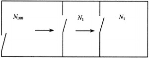
Design of buffer chamber
Suppose only when the concentration of the buffer chamber increases to x times, the increase of the concentration in the cleanroom with higher air cleanliness level will be less than 1.2 times because of the entrance of the air from the buffer chamber to the cleanroom with higher air cleanliness level (every time two people enter and the cleanroom has the most unfavorable volume). We can obtain:
 |
So
 |
If the increase of the concentration in the buffer chamber is less than 10.3 times, the volume should be calculated as follows:
 |
So
 |
This means the volume of the buffer chamber should be ≥6 m3.
The above calculation is valid for turbulent flow cleanroom. For unidirectional flow cleanroom, the difference between its air cleanliness and Class 8 is 1,000 times. Because the ability of anti-disturbance is extremely strong, pollution entering the cleanroom will be exhausted quickly by unidirectional flow, which will not influence the indoor distribution. So the buffer chamber is not needed for this case. Moreover, in Technology Regulations T.O.00-25-203 published by US Air Force and Federal Standard 209, airlock chamber and airshower chamber are not needed at the entrance of this kind of cleanroom. Only the aerospace standard specifies that airlock chamber should be considered to set for unidirectional flow cleanroom for the situations of product and people. This also applies for the buffer chamber. If buffer chamber is set for the cleanroom with Class 5, its cleanliness level can be Class 6, given the strong ability to anti-disturbance.
Buffer chamber plays the role of preventing pollution from entering the room and offsetting the differential pressure.
Two cleanrooms A and B are shown in Fig. 8.57. When positive pressure should be kept in Room A relative to Room B in the design process, where the volume of Room A or the door aperture is very large (such as the tall workshop for the assembly of satellite), a large amount of positively pressurized flow rate is needed to maintain this differential pressure. This means it is quite difficult to realize and maintain this status.
Fig. 8.57.
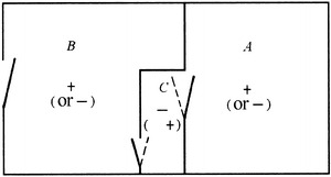
Buffer chamber with the function of offsetting the differential pressure
In this case, a buffer chamber is placed at the gate of Room A, where negative pressure is kept in Room C relative to Room A. Since the volume of Room C is very small, it is easy to maintain this negative pressure. This means positive differential pressure is maintained between Room A and Room C. Of course, Room C is also negatively pressurized relative to Room B.
This also applies for the case when Room A should be negatively pressurized relative to Room B. Buffer chamber C can also be placed, where positive pressure should be maintained in Room C relative to both Room A and Room B. The purpose of the original design is obtained.
Buffer Chamber with Negative Pressure
In order to design the isolation ward with negative pressure, the calculation formula for the isolation coefficient of the negatively pressurized buffer chamber was proposed by author [31]. The isolation coefficient means the increased ratio of the protection ability with buffer chamber to that without buffer chamber, which is expressed with β.
Figure 8.58 shows the so-called “three rooms with one buffer chamber” mode, where β 3,1 = 42.9.
Fig. 8.58.
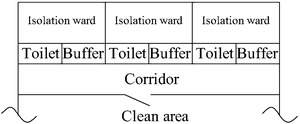
Three rooms with one buffer chamber
Figure 8.59 shows the so-called “five rooms with two buffer chambers” mode, where β 5,2 = 2042.
Fig. 8.59.

Five rooms with two buffer chambers
According to investigation result, the effect with air supply through HEPA filter in negatively pressurized buffer chamber is better by two times than that without air supply. The air change rate of exhaust air is better to be 60 h−1 (actual flow rate is very small). Even when it increases to 120 h−1, the effect only increases by 100 %.
Airshower Chamber
Since it was found that the indoor pollution concentration in cleanroom is related to the activity of the personnel, the number of occupants in the cleanroom should be limited, and the capture of particles on the surface of cloth which will generate particles during the activity should be reduced. For the latter reason, the measures to use airshower chamber was proposed in the Technology Regulations T.O.00-25-203 published by US Air Force in 1961.
The schematic of airshower chamber is shown in Fig. 8.60. But when the captured particles on the cloth surface need to be removed, vibration must be made on cloth.
Fig. 8.60.
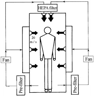
Schematic of airshower chamber
According to the hydrodynamics theory, the boundary layer is formed near the surface when air flows around an object, which is very thin. The flow inside the boundary layer is laminar. Since the laminar streamlines are parallel and the velocity is uniform, it cannot generate vibration on cloth, so the attached particles are difficult to be blown away. Only when the laminar flow in this boundary layer becomes turbulent, the movement trajectory of fluid particles is extremely irregular. The displacement occurs not only along the flow direction but also perpendicular to the movement direction. This may vibrate the cloth.
The condition for the conversion from laminar flow to turbulent flow is that Re number reaches a critical value, which is usually 1× 10⁵–5 × 10⁵.
Austin made the following calculation for Re = 5 × 10⁵ according this principle in this monograph [32]:
 |
where
V m is the critical airshower velocity (m/s);
ρ is the air density. At normal temperature it is 1.2 kg/m3;
μ is the dynamic viscosity of air (Pa · s). At normal temperature it is 1.83 × 10⁻⁵;
D is the object diameter (m).
Austin assumes the human body as circular cylinder with D = 40.6 cm, and it was obtained V m = 18 m/s (with the above parameters it should be 18.8 m/s), which is shown in Fig. 8.61. But it is not close to the real situation when the human body is considered as circular cylinder, compared with rectangle. This assumption was made during the design of slot scanning airshower chamber [33]. Given the thickness of cloth, all is based on the upper part of the cloth. Let the long side length of rectangle be b = 55 cm and the short length a = 30 cm; the equivalent diameter D′ of human body is:
 |
Fig. 8.61.
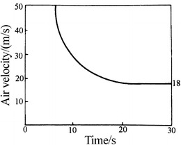
Relationship between airshower velocity and time
When average value of Re number is 3 × 10⁵,
 |
If Re number is 5 × 10⁵, V m = 19.6 m/s.
Airshower velocity does not necessarily mean the air supply velocity at the nozzle. It depends on the distance between the human body surface and the nozzle.
The net width of airshower chamber with spherical nozzle is 750–800 mm. When the length of the extruded part for both sides of the nozzles is 80 × 2 = 160 mm, which should be subtracted, the average distance between human body surface and nozzle is 108 mm. Nozzles are placed at four corners in airshower chamber with slot nozzle. The distance between the two slots is 0.9 m, so the average distance between human body surface and nozzle is 158 mm. According to hydrodynamics [34], air exiting the nozzle is the jet with circular cross section with the following core length S n at the beginning section:
 |
8.14 |
Air exiting the slot nozzle is the planar jet with the following core length S n at the beginning section:
 |
8.15 |
where
d 0 is the diameter of spherical nozzle;
b 0 is the half width of slot nozzle;
a is the turbulent coefficient of nozzle. It is 0.07 for spherical nozzle and 0.11 for slot nozzle.
Let d 0 = 38 mm and b 0 = 4 mm, we can obtain:
 |
This means the distance between human body surface and nozzle is within the beginning section in airshower chamber with spherical nozzle. Since the velocity at the beginning section is the same as the air supply velocity, the axial velocity arriving at human body surface is the exit velocity from nozzle, i.e., V 0 = V n. While in airshower chamber with slot nozzle, the distance between human body surface and nozzle is out of the beginning section. In this case, the axial velocity should be calculated with the main section instead of the beginning section for slot nozzle:
 |
8.16 |
Where V 0 is the exit velocity from nozzle, which is also called the velocity blowing towards the human body by free jet. The calculated results are shown in Table 8.9.
Table 8.9.
Exit velocity from nozzle
| Nozzle | Air supply outlet velocity V 0 (m/s) | |
|---|---|---|
| Spherical | 11.7 | 19.6 |
| Slot | 21.3 | 35.6 |
It is shown from Table 8.8 that when Re number is considered, the exit velocity from spherical nozzle should not be less than 20 m/s. When the safety coefficient is considered, it should be not less than 25 m/s.
Experiment for slot nozzle [35] has proved that the shear force with its scanning activity is larger than that of the spherical nozzle by one time. The effect of the airshower chamber with velocity 25 m/s is apparently better than that with spherical nozzle. So the exit velocity from nozzle can be 25–30 m/s.
There are different opinions about the effect of airshower chamber. First of all, the airshower chamber is effective in our opinion. Take a look at the experimental data in China [36]. The effect on “strip fabric” was tested at first. Particles attached were observed with microscope (with magnification ratio 150) before and after airshower. Results are shown in Table 8.10. Efficiency with 113 % appears in the table, which means airshower under the vibration condition can blow away the background particles on the original blank sample.
Table 8.10.
Effect of airshower on strip fabric
| Sampling state | Airshower time (s) | Efficiency for single row of nozzles with V 0 > 28 m/s (%) | Efficiency for double rows of nozzles with V 0 > 24 m/s (%) |
|---|---|---|---|
| No vibration | 30 | ~68 | ~71 |
| 60 | ~71 | ||
| 120 | ~71 | ~76 | |
| Vibration | 30 | 94–100 | 86–96 |
| 60 | 96–113 |
The second step is to paste the sample on various positions of the human body. The airshower time is 30 s. Results are shown in Table 8.11.
Table 8.11.
Effect of airshower on various positions of human body
| Position | Efficiency for single row of nozzles with V 0 > 28 m/s (%) | Efficiency for double rows of nozzles with V 0 > 24 m/s (%) |
|---|---|---|
| Top of head | 31.8 | 72.8 |
| Chest | 52.0 | 72.0 |
| Below armpit | 30.8 | 72.0 |
| Knee | 41.8 | 55.8 |
| Foot | 17.9 | 34.3 |
Since it was measured using the microscope with the magnification ratio 150, submicron particles may not be seen. The actual efficiency may be a little higher.
Next take a look at the data about particle generation after airshower with different time period in Japan [35], which is shown in Fig. 8.62. It is shown from the figure that the particle generation of particles with diameter ≥0.5 μm after 30 s of airshower in the airshower chamber with spherical nozzle reduces to about 1/6 of that before airshower, while it reduces to about 1/10 in the airshower chamber with slot nozzle.
Fig. 8.62.
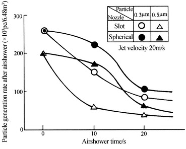
Reduce of particle generation from cloth after airshower
From the above data, we can see that the domestic effect is lower than the foreign effect, which may be related to the measurement observed by microscope.
The effect of airshower can also be evaluated from the falling particles, which is also Japanese experiment.
In the experiment, people enter the airshower chamber with the clean cloth. In the chamber the velocity is 20 m/s and the variation of particle concentration in the chamber was measured. Results in Fig. 8.63 show that the concentration (≥0.5 μm) in the airshower chamber increases by 80 times after 20 s of airshower. With the longer time, the increase of effect becomes slow.
Fig. 8.63.
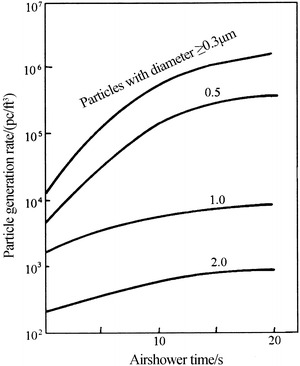
Relationship between falling particle number and airshower time
Secondly, the actual effect of airshower chamber is not so good as the theoretical and experimental effects. The reasons are as follows:
Some operators overestimate the function of airshower chamber which prevents large amount of particles from entering the cleanroom.
The airshower chamber is designed improperly. The number of nozzles can be different by more than one time. Some chamber has no nozzle at the ceiling. Some only set a row of nozzle, while it is shown from the previous data that the effect with two rows is better than one row, because of the enlarged exposed area on human body to the airflow. Some only place nozzle at one side.
The airshower velocity is too small. According to some measurements, the velocity at the nozzle exit is usually 10 m/s or even lower.
During usage, people usually try to avoid the airflow, or open the door with shortened time (doors are not interlocked).
The flow direction should be inclined to, instead of perpendicular to, the cloth surface. This means the angle of nozzle should be adjusted not to face people directly. The opposite nozzles should not be face-to-face. It is recommended to install as shown in Fig. 8.64 [34].
People in the airshower chamber do not cooperate to rotate or vibrate the cloth.
Fig. 8.64.
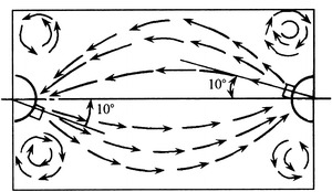
Direction of nozzles
It should be emphasized that given the interlock relations between two doors in the airshower chamber, the airshower chamber can be considered as the airlock chamber which can be used to perform the airshower process. The Technology Regulations T.O.00-25-203 published by US Air Force has ever pointed out that “the entrance and exit doors can be interlocked with the combination of airshower chamber and airlock chamber” and “the standing airshower chamber in the cabinet should be placed in the middle of the airlock chamber.”
In the monograph of Austin [32], “airshower process is usually placed in the airlock chamber,” and “after the entrance of personnel and the close of the door, air with high speed flows towards the cloth. After the airshower process is complete, people can enter the working area with higher requirement.”
There is certain efficiency for airshower chamber, but it does not mean airshower chamber must be placed for any cleanroom.
Suppose the occupant density is 0.2 p/m2, namely, there are two people in the space 25 m3 (10 m2). If people do not pass through the airshower chamber, the average particle generation during activity is 0.45 × 10⁶ pc/(min · p) (with white nylon clean working garment). The influence on various air cleanliness levels is shown in Table 8.12.
Table 8.12.
Influence with no airshower process
| Air cleanliness level | Average particle concentration (pc/L) | Air change rate (h−1) | Particle generation rate (pc/h) | Increase of particle concentration for each liter of air (pc) | Increase of particle concentration (%) | Variation of air cleanliness level |
|---|---|---|---|---|---|---|
| 100,000 | 2000 | 15 | 5.4 × 10⁷ | 144 | 7.2 | 100,000 |
| 10,000 | 200 | 25 | 5.4 × 10⁷ | 86.4 | 43.2 | 10,000 |
| 1,000 | 20 | 50 | 5.4 × 10⁷ | 43.2 | 216 | 10,000 |
| 100 | 2 | 450 | 5.4 × 10⁷ | – | – | – |
The design concentration of cleanrooms with various air cleanliness levels cannot be the upper limit of the corresponding concentration, which is usually 1/3–1/2 of the upper limit. Now assume the average concentration between the upper and lower limits is used. It is known from the above result that for cleanroom with air cleanliness Class 8, the concentration will increase by 144 pc/L when no airshower chamber is used, but it will not influence the designed air cleanliness level. For cleanroom with air cleanliness level Class 7, the air cleanliness level will not be affected with the above assumptions, but it will be influenced when the average concentration is 300 pc/L. So for cleanroom with air cleanliness level Class 7, the airshower chamber is usually not necessary. But if the requirement is higher, it should be considered. The airshower chamber should be placed for cleanroom with Class 6. For cleanroom with Class 5, it should not be considered with the above principles. Because the flow in cleanroom with Class 5 is unidirectional, the generated particles from occupant will not mix with the room air; instead, they will be exhausted away by unidirectional flow. Transverse exchange will not be considered. This is the reason why the anti-disturbance ability is strong in unidirectional flow cleanroom, and it is not necessary to install airshower chamber. In both the Technology Regulations T.O.00-25-203 published by US Air Force and the Federal Standard 209A and 209B, it is specified that “airlock chamber and airshower chamber are usually not necessary for this kind of cleanroom.” For unidirectional flow cleanroom with special purpose, NASA NHB 5340-2 specified that “airlock chamber and airshower chamber should be applied according to the purpose of product and personnel.” This means these two kinds of chambers should be considered to install for unidirectional flow cleanroom, or sometimes it may be not necessary. But from another point of view, airshower chamber is placed even when it is not necessary, which aims to strength the impression and generate the psychological effect. The inner side of airshower chamber is already the clean area! This has already been noticed in the foreign literatures.
There are some applications where the airshower chamber cannot be installed. In some place the airflow with high speed is not allowed. For example, at the entrance of the operating room or some intensive care unit, patient cannot bear the airshower with high speed. The entrance process will be affected because the floor of the airshower chamber is higher than the outside. The airshower chamber will not operate properly when the object is too long or too wide, which is larger than that of the airshower chamber. The time to pass through is very long and continuous that the airshower chamber cannot operate. There are too many personnel that it takes a lot of time to pass through the airshower chamber.
Someone may be afraid that after the airshower process, will particles and bacteria falling down from the human body enter the cleanroom?
As long as it is properly designed, the door will be opened only when the airshower process is completed. In this way, particles will not leave from the chamber. The airshower chamber should be negatively pressurized. According to the Technology Regulations T.O.00-25-203 published by US Air Force, the airshower chamber should be positively pressurized relative the outside, so that no problem will appear. But this has not been realized for the current chamber. Only zero pressure is realized. According to the foreign report, the influence of the opening of the door after the airshower process is meaningful only for cleanroom with air cleanliness level higher than Class 5.
Feature of Cleanroom with Full-Ceiling Air Supply and Two-Bottom-Side Air Return
The technological and economic meaning of the cleanroom with full-ceiling air supply and two-bottom-side air return mode has been understood from the previous introduction about the classification of unidirectional flow cleanroom. But what is the characteristic of this kind of cleanroom? Can it replace the vertical flow cleanroom with the standard air return on the grille floor? What is the maximum width? If it is too wide, it is natural to worry about whether unidirectional flow can be formed in the working area, or whether the above index can be satisfied. A foreign study has put forward that when the width of the cleanroom of this kind is less than 3.6 m, the air cleanliness level can reach Class 5 in American Federal Standard [5]. But results of further study were not provided. Since 1970s, the comprehensive investigation from line sink theory, experiment, and field test was initiated in China [7]. The allowable width of this kind of cleanroom and many features of the flow field were obtained, which provides the basis for the promotion of the cleanroom. It is easy to obtain the flow field of this kind of cleanroom with computational simulation. But it is much easier for understanding the physical meaning by the line sink theory. The derivation of this theory will be introduced below.
Line Sink Model
Flow Pattern of the Line Sink
Figure 8.65 shows the flow pattern along x- and y-directions for the cleanroom with full-ceiling air supply and two-bottom-side air return. Along the z-direction which is perpendicular to the paper, the flow properties (such as velocity and pressure) are the same. This properties (mainly the velocity) are only related to x and y, while it is not related to z. This kind of flow pattern is the special case of the flow field, namely, planar flow, and there is no eddy in the flow field.
Fig. 8.65.
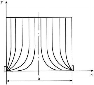
Flow field along x- and y-directions with two-bottom-side air return
For ideal planar flow without eddy, there exists a function ψ(x, y):
 |
where u x and u y are the components of the velocities along x- and y-directions, respectively. ψ is the stream function.
According to the physical meaning of ψ, ψ is a function for the planar position (x, y). One value of ψ will be given for every position (x, y). Let
 |
We obtain:
 |
i.e.,
 |
This is the streamline function. When the positions with the same value of ψ are linked together, the streamlines are generated. The problem is how to obtain the value of ψ.
According to the hydrodynamics, there is a complex potential for planar flow without eddy. This complex potential is composed of stream function and potential function, where the imaginary part is the stream function.
 |
8.17 |
If the complex potential W(Z) of the flow field can be found and decomposed into the real and imaginary parts, the stream function can be found.
It is shown in Fig. 8.66 that two rows of infinite sinks, i.e., line sinks, with interval distance b have the similar flow pattern as shown in Fig. 8.65.
Fig. 8.66.
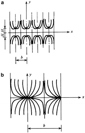
Flow field with two rows of line sinks
Stream Function
If there is a pair of sinks parallel to the y-axis and the distance from x-axis approaches zero (which is equivalent to the situation when the return air grille is at the floor, the bottom of Fig. 8.66), the flow pattern is as shown in Fig. 8.65. So when the condition of the problem is the same as that in Fig. 8.66, the corresponding stream function and complex potential are that in Fig. 8.65.
The conditions to form the sink flow as in Fig. 8.66 include the following items:
The streamlines along y-direction are parallel, and they bend with the effect of sink.
Flow properties do not vary along z-direction.
x-axis, y-axis, and the longitudinal axis are streamlines. If the partition wall is placed along these axes, the shape of streamlines will not be affected.
The actual flow field shown in Fig. 8.65 meets the above three conditions.
Since the height of the room has a certain value. After air passes through HEPA filter or the damping layer at the ceiling, the streamlines are almost parallel, which meets the first condition.
It is planar flow and the flow properties are independent of z-axis, which meets the second condition.
The side wall and the floor are equivalent with y-axis and x-axis in Fig. 8.61, respectively. So other streamlines are not affected by these walls. There is an invisible wall at the position b/2, which separates the room into two parts. It meets the third condition.
Except for the above three aspects of similarities, the most difference is that the return air grille is not a line sink since it has a certain amount of height. So it is approximated when the sink model is used. This should be investigated through experiment.
The complex potential in Fig. 8.66 is known [37]:
 |
8.18 |
where Q 0 is the flow rate of return air at each side and b is the interval between two rows of sinks, namely, the width of the cleanroom:
 |
From Eq. (8.18), we know
 |
8.19 |
Since we know
 |
 |
Let  , so we obtain
 |
8.20 |
The derivation process is omitted.
According to the definition of complex number, the magnitude of P = U + iV is:
 |
8.21 |
And the angle is:
 |
8.22 |
Because we know
 |
With Eqs. (8.19) and (8.20), we obtain
 |
8.23 |
The stream function can be obtained with Eqs. (8.17) and (8.23):
 |
8.24 |
Since positions with the same value of stream function are located in the same streamline, we obtain the following expression for every streamline:
 |
8.25 |
With the value of each constant, the corresponding values of x and y can be obtained. The streamlines can thus be obtained. Figure 8.67 shows the plotted flow field. It fits well with the measured results by water model with 1/40, 1/30, 1/20, and 1/10 scales, as well as the field test results.
Fig. 8.67.
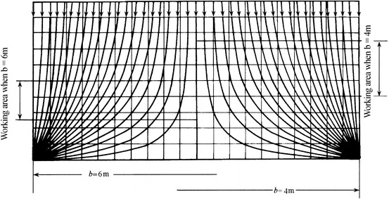
Theoretical flow field of cleanroom with full-ceiling air supply and two-bottom-side air return
Figure 8.68 shows the schematic of water model. Figure 8.69 shows the cleanroom model made with organic glass.
Fig. 8.68.
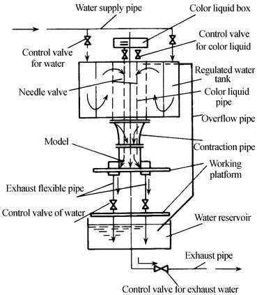
Schematic of water model system
Fig. 8.69.
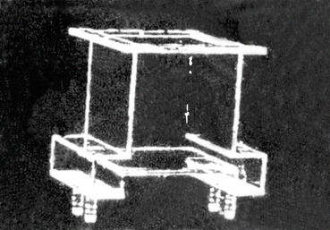
1/30 cleanroom model. The black line represents the streamline of the colored liquid, i.e. the airflow streamline.
In the model experiment, water with common temperature was used as the working medium in the model. Colorful liquid was injected into the water, so that the streamline is visible and it is easy for observation and photograph. The scale of test equipment can be reduced when water is used as the working medium, because the dynamic viscosity of water with common temperature is much smaller than that of air with common temperature and the ratio is 1/15. When the geometric size of the model is fixed, the proportional scales of velocity and flow rate with the ratio of 15 were obtained. When the streamline at the position  is used as the reference (the reason will be shown later), the measured and theoretical streamlines of four models will be plotted on Fig. 8.70. It is shown that various streamlines are similar when Re is above 6,000.
Fig. 8.70.
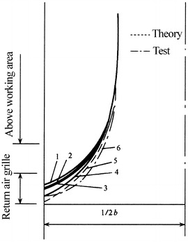
Streamlines at the position b/4 of four models (Re > 6,000). 1 1/30 model, Re = 8,500, 1/40 model, Re = 6,000; 2, 3 1/10 and 1/20 models, Re = 6,800–20,000; 4 1/40 model, Re = 5,000 and height of return air grille = b/13; 5 theoretical streamline; 6 1/10 model, Re < 2,000
When the theoretical model with extrapolated sink point was used for calculation, the difference between the ordinates of the theoretical and measured streamlines at the position  is about
  . The inclination degree is almost seldom changed, which is shown in Figs. 8.71 and 8.72.
Fig. 8.71.
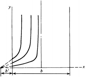
Situations with extrapolated sink point
Fig. 8.72.
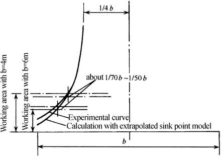
Deviation of calculated curves
The actual return air grille has a certain amount of height itself, and its bottom side is also a certain distance away from the floor. This is equivalent with the case when there is a distance between sink and floor, which is assumed to be H. The stream function can be derived:
 |
8.26 |
H is usually very small, and it is less than 0.05b. So  , which is a little larger than the value “1” in Eq. (8.24). This has small influence on calculated results. Streamlines bend downwards slightly near the sink position and then upwards, which is shown in Fig. 8.80 in the next section.
Fig. 8.80.
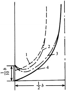
Streamlines with different distances between the bottom of return air grille and the floor; 1 experimental streamlines when height of return air grille is b/10, and distance from the floor is b/20; 2 experimental streamlines when height of return air grille is b/20, and distance from the floor is b/10; 3 experimental streamlines when height of return air grille is b/10, and distance from the floor is b/10; 4 Experimental streamlines when height of return air grille is b/10, and the bottom is on the floor
Feature of Flow
Basic Feature
Two streamlines at two sides and in the middle (including these near the floor) are straight lines. Curved streamlines appear firstly at the position of 1/4 width (i.e., b/4). The streamlines become straighter when it goes towards two sides. This is completely opposite with the opinion that the farther it is from the return air grille, the much curved the streamline is. Theoretical, experimental fields (Fig. 8.73) and field tested flow field (Figs. 8.74 and 8.75, both are cited from the test report from Institute of HVAC at Chinese Academy of Building Science) all show the same trend, which can be used to provide the proof.
It is shown from the theory of sink that the flow field is already determined when the value of b is fixed. The flow field will be contracted with smaller b, when the streamlines tend to move downwards.
In the middle bottom region, the velocity gradient between streamlines becomes larger when it approaches to the center, and the curvature of the streamline gets larger. The triangular region appears which is opposite from the definition of unidirectional flow. This kind of triangular region appears in both experimental and field test, and the scale of the latter is relatively small. In experiment, since colorful liquid is used, the scale of the triangular region is larger. When the velocity increases a little, it will appear. The height is about 0.15b, especially 0.1b, away from the bottom, which is shown in Fig. 8.76.
Fig. 8.73.
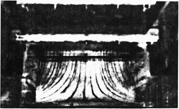
Photograph of flow field measured with water model (1/10 model) with the height of return air grille  . The black line represents the streamline of the colored liquid, i.e. the airflow streamline.
Fig. 8.74.
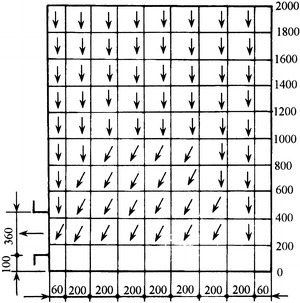
Measured flow field in the cleanroom with bottom return air at one side
Fig. 8.75.
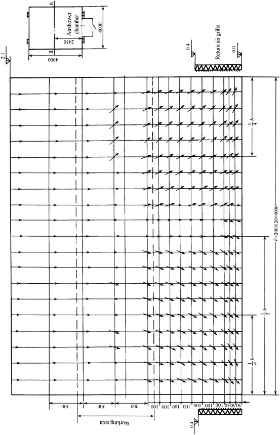
Measured flow field in JJS20 type assembly cleanroom with two-bottom-side air return
Fig. 8.76.
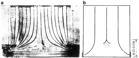
Situation of triangular region at the central bottom place. (a) Photo. (b) Visual inspection record (1/40 model, Re = 50,000)
The triangular region in the experiment was not obvious, which can be found in the flow field figure shown above. The possible reasons include: (1) The widths of two examples were both narrow. It was only 1.52 m in the latter case (one side). (2) Thread method was adopted to measure the streamlines. Since the weight itself caused influence, the streamlines measured in experiment show straighter. But when particles were generated in the triangular region, the self-purification process was quite difficult, which means the flow in this place is different from unidirectional flow. Although the theoretical calculation above did not provide the basis for the existence of eddy in this triangular region, the recent computational simulation also presents the same conclusion (shown in Fig. 8.77 [38]). So it is not certain that there must be an eddy flow in the center of cleanroom. Even though the triangular region exists, the turbidity will not influence the flow field in the working area. But it is clear that the streamlines in this triangular region is different from unidirectional flow without a doubt. In this aspect, this kind of triangular region with obvious curved bifurcation of streamlines is not allowed to exist in the working area of cleanroom with full-ceiling air supply and two-bottom-side air return mode, where the flow field in this kind of cleanroom is thought as unidirectional. So the height of the triangular region is an important feature to evaluate the unidirectional flow property of this kind of cleanroom. Therefore it is necessary to limit the width of this kind of cleanroom. It should be mentioned that since the boundary conditions cannot be given precisely, it is very difficult to simulate the turbulent flow and eddy with computer.
Fig. 8.77.
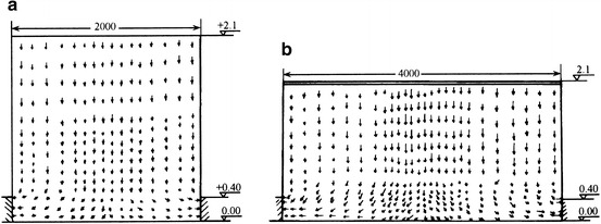
Simulated flow fields. (a) Room width 2 m. (b) Room width 4 m
Influence of Return Air Grille
Influence of the Resistance of Return Air Grille
The resistance of return air grille has significant influence on the turbidity of the streamlines. For the return air grille with complete opening, streamlines will vibrate even for very low velocity according to experiment. When perforated plate is added, no vibration will occur in streamlines even when the velocity is much larger. Figures 8.78 and 8.79 show the streamline photo with the same velocity, which proves this point. The reason may be that the resistance of return air grille is uniformly distributed with perforated plate, so that each pore on the perforated plate is equivalent with the sink with the same intensity, which is beneficial for the uniformities of velocity field and streamlines. Therefore, during the actual design process, it is not enough to place net and grille on return air opening. When the resistance is allowed, coarse and medium air filters should also be installed, which is the requirement of cleanroom itself.
Fig. 8.78.
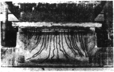
Streamlines when return air grille is opened (1/10 model) (height of return air grille = b/10)
Fig. 8.79.
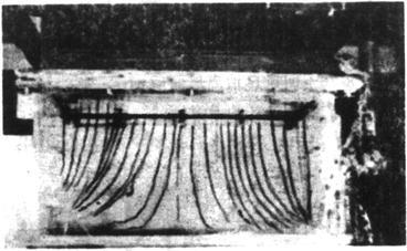
Streamlines when perforated plate is added on return air grille (1/10 model) (height of return air grille = b/10)
Influence of the Height of Return Air Grille
The variation of opening height of return air grille itself has little influence on the streamline trajectory. But with simulated results, it is shown that the less the height is, the smaller the inclination degree of the streamlines above the working area is. So this means the streamlines are straightened [38].
Influence of the Distance Between the Bottom of Return Air Grille and the Floor
Figure 8.80 shows the experimental and calculated results of the streamlines with different distances between the bottom of return air grille and the floor. It is shown in the experiment that when the bottom is elevated, the trend of the streamlines does not change, except that streamlines bend slightly downwards near the return air grille. When the elevated distance is very small, it is hard to observe the shape of curvature (such as curve 1). Moreover, when it is elevated more, streamlines tend to be close to the center. At the same time, the curved streamline may reach the floor, which will blow particles on the floor easily. These results are consistent with the theoretical law.
This means for whatever kinds of cleanroom, it’s better not to elevate the return air grille on the side wall; otherwise particles on the floor will be blown away, and pollution range will be expanded. It is shown in Fig. 8.81.
Fig. 8.81.
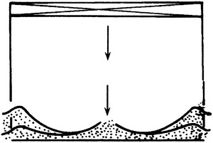
Schematic of the expanded pollution range when the return air grille is elevated
Influence of Number of Slot Return Air Grille
Slot air return grilles are usually placed at the bottom of side wall in cleanroom with two-bottom-side air return model and can also be placed on the floor. Figures 8.82 and 8.83 present the experimental streamline photo when return air grille with three slots and four slots is placed on the floor respectively. It is shown that streamlines with four slots are straighter than three slots. This is because the case with three slots is equivalent with the room width b/2, while the case with four slots is equivalent with the room width b/3. With the theoretical calculation, streamlines are much straighter. It can be conceived that for the cleanroom with large width, return air channel with multiply slots on the floor can be used, as long as the suitable unit length b is kept, which is shown in Fig. 8.66.
Fig. 8.82.
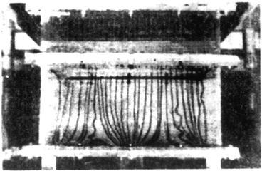
Air return grille with three slots on the floor (the total area of return air grille is 20 % of the floor)
Fig. 8.83.
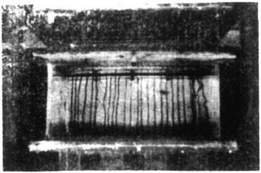
Air return grille with four slots on the floor (the total area of return air grille is 40 % of the floor)
Influence of Return Air at One Side and Nonequivalent Return Air at Two Sides
Figure 8.84 is the experimental streamline photo for return air at one side, which is equivalent with the doubled room width. It is shown that streamlines are more inclined compared with two-side air return mode. The triangular region originally located in the central bottom of the cleanroom moves to the left corner.
Fig. 8.84.
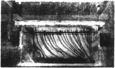
One-side air return mode
It is imaginable that when appropriate air return is provided at the left corner, the flow condition will be ameliorated. Results are shown in Fig. 8.85. When return air with a few amount of flow rate is added on the left corner (which means flow rates at left and right sides are different), the streamlines’ condition is improved. The triangular region is reduced and the position also changes.
Fig. 8.85.
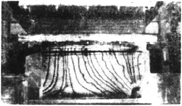
Nonequivalent return air at two sides
The above introduction shows that nonequivalent return air at two sides (when the room width is small, return air with small amount of flow rate can be placed) can be used, if two-side air return mode is not possible, because of the allocation of process or the narrow room width. It also applies for the case when larger triangular region may appear with one-side air return mode for relatively large room width, or it is hoped to remove the triangular region since the process should be placed in the center of the room. For example, there is one cleanroom with width 3 m, one-side air return mode is used, and an opening with many holes is placed at the other side, so that air is exhausted here with the positively pressurized air. It is not organized return air, but the flow field condition is also ameliorated. The triangular region is too small at one side to be measurable, which is shown in Fig. 8.86. All these methods make it flexible to apply the two-bottom-side air return mode.
Fig. 8.86.
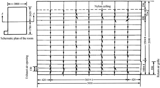
Flow field in one cleanroom with one-side air return and one-side air exhaust mode
Allowable Room Width
With above features of the flow field in the cleanroom, two aspects are mainly considered for determination of the allowable room width.
With the allowable room width, the working area (0.8 m above the floor) should be above the height of the triangular region.
It is shown from the above water models that the average height of this triangular region can be 0.125b. When the height of working area is assumed 0.8 m, b can be a little larger than 6 m.
-
2.
With the allowable room width, the inclination angle of streamlines in the specified region should be larger than 65°.
From the flow field figure obtained by theoretical calculation, the streamlines are used as reference at the place b/4 where curve first appears. The inclination angle in the region between 0.75 and 1.8 m above the floor can be obtained:
 |
 |
So when b is slightly less than 6 m, the inclination angle of the streamline can be larger than 65°.
The above results are shown in Figs. 8.87 and 8.88.
Fig. 8.87.
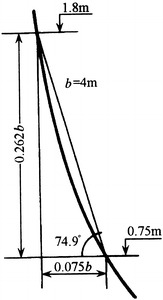
Inclination angle of streamline when b = 4 m
Fig. 8.88.
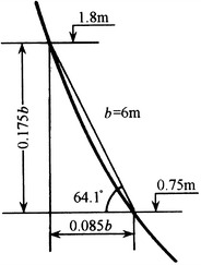
Inclination angle of streamline when b = 6 m
From the above two aspects of analysis, when the width of cleanroom with full-ceiling air supply and two-bottom-side air return mode is not larger than 6 m, it can be thought as the unidirectional flow cleanroom. When the room width is less than 5 m and the limit is supposed 5 m, it is much stricter and the corresponding inclination angle is 69°. This is why it is recommended so in “Design guideline of cleanroom factory” published in 1984 (GBJ 73-84). According to field test, the air cleanliness level can reach Class 5. For the above two examples with field test, the indoor particle concentrations under as-built status are 0.026 pc/L (≥0.5 μm) and 0.24 pc/L (≥0.5 μm), respectively.
References
- 1.NASA SP-5076 (1969) Contamination control handbook, Sandia National Laboratories
- 2.Morrison PW (1973) Environmental control in electronic manufacturing. Van Nostrand Reinhold Company, New York, USA
- 3.Institute of HVAC of China Academy of Building Research (1973) Assembly thermostatic cleanroom, pp 6–7 (In Chinese)
- 4.Sato E. Status of industrial cleanroom. J Jpn Air Clean Assoc. 1976;13(8):32–41. [Google Scholar]
- 5.Meckler M. Packaged units provide clean room conditions in moon rock. Heat Pip Air Cond. 1970;42(7):71–76. [Google Scholar]
- 6.Кочерин ИД (1978) Air cleaning technology in production of semiconductor and integrated circuits (trans: 10th design research institute of the former fourth machinery industry department) (In Chinese)
- 7.Xu ZL, Shi NS, Lu Y (1981) Research of airflow characteristic in cleanroom with air supply fully at the ceiling and air return at two bottom sides. Research at Institute of HVAC of China Academy of Building Research, p 11 (In Chinese)
- 8.Fitzner K. Luftstromungen in raumen mittlerer Hohe Bei Verschiedenen arten von Luftauslassen. Gesundheits Ingenieur. 1976;12:293–300. [PubMed] [Google Scholar]
- 9.Карпис ЕЕ (1975) Кондиционирование Воздуха В Чистых Помещениях. Холодилъная техника 1:54–58 (In Russian)
- 10.Kikuchi I (1969) Design of dust-free sterile environment. Jpn Air Cond Heat Refrig News 9(1):91–96 (In Japanese)
- 11.Naoi T. Eye curtain” by the combination of vertical laminar flow and air curtain. J Jpn Air Clean Assoc. 1979;17(1):47–49. [Google Scholar]
- 12.Rivenburg H. Environmental control for high big clean room. Heat Pip Air Cond. 1973;45(3):57–64. [Google Scholar]
- 13.Wuhan Institute of Hydraulic and Electric Engineering . Hydrodynamics. Beijing: Water Conservancy and Electric Power Press; 1960. [Google Scholar]
- 14.Finkelstein W, Ritzner R, Moog W. Measurement of room air velocities within air conditioned buildings. Heat Ventilat Eng J Air Condit (Part 2) 1975;49(575):6–11. [Google Scholar]
- 15.Department of HVAC. Water Supply & Exhaust at Xi’an Metallurgy College . Fluid dynamics. Beijing: China Industrial Press; 1961. [Google Scholar]
- 16.Xu ZL, Qian ZM, Shen JM et al (1983) Lower limit of air velocity in parallel flow cleanroom. Research at Institute of HVAC of China Academy of Building Research, p 11 (In Chinese)
- 17.Hayakawa K (1980) Air conditioning in comprehensive hospital. Jpn Air Cond Heat Refrig News 20(8):51–59 (In Japanese)
- 18.Kato S. Selection method of air cleaning devices for different application. Jpn Air Cond Heat Refrig News. 1971;11(9):103–110. [Google Scholar]
- 19.Kawamoto S et al (1971) Design planning of cleanroom for industrial facilities (No.1), Jpn Air Cond Heat Refrig News 11(9):91–100 (In Japanese)
- 20.Nishi T, Sakamura T (1980) Actual situation of cleanroom design in recent comprehensive hospitals. Jpn Air Cond Heat Refrig News 20(8):81–85 (In Japanese)
- 21.T.O.00-25-203 (1972) Contamination control of aerospace facilities. Technology Regulations of U.S. Air Force
- 22.Xu ZL (1994) Design of cleanroom. Seismological Press, Beijing (In Chinese)
- 23.Zhang WG (1992) Experimental study of radial flow cleanroom model. Master dissertation of Harbin Building Engineering College (In Chinese)
- 24.Wei XM, Fan HM, Zhang WG (1994) Numerical simulation and experimental assessment of radial flow cleanroom. In: Proceedings of the annual national conference on HVAC&R, pp 232–235 (In Chinese)
- 25.Wei XM, Sha L. Numerical simulation of one cleanroom with new type of air supply and return modes. Contam Control Air Cond Technol. 2001;3:13–17. [Google Scholar]
- 26.Xu ZL (2006) Design principle isolation ward. Science Press, Beijing, p 39 (In Chinese)
- 27.Kita J, Isono K, Morikawa K. Dynamic characteristics of opening and closing of door in cleanroom for solid dosage workshop and related study on migration of airborne particles. J Soc Heat Air Cond Sanit Eng Jpn. 2004;95:63. [Google Scholar]
- 28.Zhao HZ, Zhai HL. Infiltration air velocity calculated with the safety probability method in China. J HV&AC. 1994;24(1):16–20. [Google Scholar]
- 29.Xu ZL, Shen JM (1989) Application of air cleaning technology. China Architecture & Building Press, Beijing, p 222 (In Chinese)
- 30.Japan Air Cleaning Association (1981) Handbook of air cleaning. OHM Press, Japan, p 450 (In Japanese)
- 31.Xu ZL. The application of surge chamber of negative pressure isolating room. Build Sci. 2005;21:52. [Google Scholar]
- 32.Austin PR, Timmerman SW (1965) Design and operation of clean rooms. Business News Publ, Detroit
- 33.Editorial Department of Chinese Contamination Control Society (1989) Development report of HG-8801 slot scanning airshower chamber (In Chinese)
- 34.Moren Z (1979) Fluid dynamics-pump and fan. China Architecture & Building Press, Beijing, p 236 (In Chinese)
- 35.Fukao H (1985) Chapter 5: Evaluation experiment on airshower. In: Evaluation study of cleanroom performance (exchanged paper) (In Japanese)
- 36.Institute of HVAC of China Academy of Building Research (1973) Assembly thermostatic cleanroom, pp 62–69 (In Chinese)
- 37.Талиев ВН (1963) Азродинамнка Вентнляции (In Russian)
- 38.Li BT, Wei XM. Study of the characteristic of cleanroom with air supply outlet fully placed at the ceiling and return air grille on both side walls. J Harbin Build Coll. 1997;30(3):59–62. [Google Scholar]


