Abstract
A high-resolution 1.3-GHz/54-mm low-temperature superconducting/high-temperature superconducting (HTS) nuclear magnetic resonance magnet (1.3 G) is currently in the final stage at the Massachusetts Institute of Technology Francis Bitter Magnet Laboratory. Its key component is a three-coil (Coils 1–3) 800-MHz HTS insert comprising 96 no-insulation (NI) double-pancake coils, each wound with a 6-mm-wide GdBCO tape. In this paper, after describing the overall 1.3-G system, we present innovative design features incorporated in 1.3 G: 1) an NI winding technique applied to Coils 1–3 and its adverse effect in the form of charging time delay; 2) persistent-mode HTS shims; 3) a “shaking” magnet; and 4) preliminary results of Coil 1 operated at 4.2 K.
Index Terms: High-temperature superconducting (HTS) shim coils, inside-notch double-pancake (DP) coil, low-temperature superconducting (LTS)/HTS nuclear magnetic resonance (NMR) magnet, screening-current-induced field (SCF) shaking magnet
I. INTRODUCTION
IN NUCLEAR magnetic resonance (NMR), the well-known advantages of higher magnetic field are improved resolution and higher sensitivity. This enables the examination of complex molecular systems such as proteins in a much shorter time frame or with smaller quantities of material. Most solution NMR experiments utilize the TROSY effect to optimize the resolution of the experiments. Initially, it was predicted that TROSY experiments would be optimal at ~900 MHz. However, more recent experimental data on several proteins indicate that the resolution is optimized in the range of 1200–1400 MHz[1]. In magic-angle-spinning solid-state NMR, the optimal field is simply the highest field available [2]. This 1.3-GHz NMR magnet is expected to become a significant resource for the entire NMR community.
From the outset in 1999 when we proposed a three-phase project to build a high-resolution 1-GHz NMR low-temperature superconducting (LTS)/high-temperature super-conducting (HTS) magnet (1 G) to the National Institutes of Health (NIH) [3], our design philosophy for a ≥1-GHz NMR magnet is based on the following key decisions: 1) a combination of an LTS magnet and an HTS insert; and 2) all HTS inserts to be assemblies of double-pancake (DP) coils: 50-MHz (Phase 1) [4], [5] and 100-MHz (Phase 2) [6]–[9], both of Bi2223 tape. At the beginning of Phase 3 of this 1 G project, when, upon recommendation by the NIH, the frequency goal was raised to 1.3 GHz, we decided on a combination of a 700-MHz LTS NMR magnet and a 600-MHz HTS insert (H600), two nested coils of REBCO (Coil 1) and Bi2223 (Coil 2) [10], [11]. In 2012, after a theft, in late 2011, of a nearly completed H600, two versions were considered: first, a 700-MHz GdBCO-Bi2223 insert, i.e., H700 [12], and later the H800 [13]. In December 2012, we adopted a combination of a 500-MHz LTS NMR magnet (L500), already available in the Francis Bitter Magnet Laboratory, and H800 to complete a high-resolution 1.3-GHz LTS/HTS NMR magnet (1.3 G). Note that our 1.3 G relies on a greater field contribution of an HTS insert than an LTS magnet: 18.79 T versus 11.74 T.
II. INNOVATIVE DESIGNS IN H800
The following innovative designs are embodied in H800.
NI Winding Technique
A no-insulation (NI) winding technique [14]–[18] is applied to all DP coils in H800. Its effect on Coils 1–3 are discussed later.
Inside-Notch Pancake Coil
Generally, the longer the overall height of a magnet, the better its inherent field homogeneity [19]. Therefore, to compensate H800, which is shorter than the original H600, those DP coils in the H800 located at the center region are “inside-notched”—the very first this classic field-homogeneity-enhancing technique is deployed to HTS DP coils.
Persistent-Mode HTS Shim Coils (Shims)
The room-temperature bore of a superconducting magnet is magnetically shielded by the “diamagnetic walls” of its own coils. To ameliorate field shimming in our 1.3 G, we have been developing a new shimming technique that relies on a wide YBCO tape. Specifically, persistent-mode HTS shims [20] will be placed in narrow annular space between the liquid helium (LHe) bore tube and Coil 1 innermost winding diameter. This will be discussed later.
“Shaking” Magnet A
“shaking magnet” [21]–[28] to reduce the error fields generated by screening-current-induced field (SCF) [7], [29]–[33] will be installed in the 1.3 G. A design for our 1.3 G based on the performance of a shaking magnet [33] will be presented later.
LHe Recondensation
To mitigate the rising cost of LHe, which is expected to continue for the unforeseeable future, the1.3 G, operated at 4.2 K in a bath of LHe, will be equipped with an LHe recondenser [34].
III. OVERALL SYSTEM
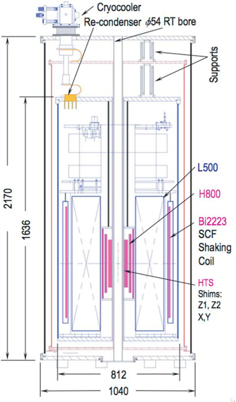
The 1.3 G comprises the L500 and H800; its overall to-scale schematic drawing is shown in Fig. 1. The key components of the 1.3 G are indicated in the figure: L500; H800; HTS shims, Z1, Z2, X, Y; Bi2223-wound SCF shaking magnet. Before discussing the NI technique, presenting designs of HTS shims, a design of shaking magnet, and 4.2-K results of Coil 1, we present below key parameters of L500, H800, and GbBCO tape, including its properties.
Fig. 1.
Cross section of 1.3 G.
L500
This persistent-mode 500-MHz MRI magnet can be operated in the temperature range 4.2–6 K [35]. It chiefly consists of Nb3Sn coils. The key parameters are listed in Table I. In the previous runs, it never quenched.
TABLE I.
L500 (11.74 T)
| Operating temperature | [K] | 4.2–6.0 |
| Cold bore for H800 | [mm] | 237 |
| Over all diameter; height | [mm] | 780;1422 |
| Magnet mass | [kg] | 1200 |
| Magnetic energy @ Iop=246 A. | [MJ] | 4.6 |
| Temporal stability | [ppm/hr] | < 0.01 |
| Measured field homogeneity | [ppm] | 0.45* |
17-mm diameter × 30-mm length.
H800
Table II lists its key parameters.
TABLE II.
H800 (18.79 T) IN L500 AT 4.2 K
| Parameter | Coil1 | Coil2 | Coil3 | |
|---|---|---|---|---|
| Frequency/field | [MHz/[T]] | 369/8.66 | 242/5.68 | 189/4.44 |
| Ic @77K, self field (sf) | [A] | > 160 | ||
| B⊥ | [T] | 4.8 | 4.6 | 3.7 |
| Ic(B⊥,4.2K)/Ic(77K,sf) | > 2.3 | > 2.3 | > 2.7 | |
| Operating current/density | [A]/[MA/m2 | 251.3/546.9 | ||
| Total # DP coils (notched) | 26(6) | 32(8) | 36(8) | |
| # turns/pancake | 185.1 | 121 | 95 | |
| # turns/notched pancake | 176.6 | 118 | 93 | |
| Winding i.d. | [mm] | 91.0 | 150.7 | 195.9 |
| Winding i.d. (notch) | [mm] | 92.4 | 151.2 | 197.2 |
| Winding o.d. | [mm] | 117.6 | 167.9 | 210.1 |
| Windingn overall height | [mm] | 323.7 | 392.1 | 465.7 |
| Notched section height | [mm] | 74.7 | 122.5 | 98.0 |
| SS overband radial build | [mm] | 7 | 5 | 3 |
| GdBCO length/DP | [m] | 121.9 | 121.5 | 121.8 |
| GdBCO length/notch DP | [m] | 116.7 | 118.7 | 119.3 |
| Total length/Coil | [km] | 3.14 | 3.84 | 4.61 |
| Inductance | [H] | 2.43 | 3.08 | 3.71 |
| Peak bending strain | [%] | 0.060 | 0.036 | 0.028 |
| Peak magnetic hoop strain | [%] | 0.41 | 0.35 | 0.32 |
| Peak total hoop strain | [%] | 0.47 | 0.39 | 0.35 |
| Radial strain | [%] | < −0.1 | < −0.1 | < −0.1 |
| Rm (Eq.l for Coils 2,3) | [mΩ] | 17.6 | 9.1 | 9.1 |
| τm (Eq.2 for Coils 2,3) | [s] | 138 | 624 | 603 |
GdBCO
Each coil is wound with SuperPower GdBCO coated tape: 6 mm wide and 75 μm thick, of which the Hastelloy substrate is 50 μm thick, and the 5-μm-thick remainder comprises a 1-μm-thick GdBCO layer and other materials. A 10-μm-thick copper layer is electroplated over the entire surface. Table III summarizes the parameters and properties of the GdBCO tape. It also includes those of a G10 spacer between pancake coils.
TABLE III.
GDBCO TAPE: PARAMETERS AND PROPERTIES
| Non-GdBCO material | Hastelloy | Cu & others | |
| Overall width/thickness | [mm/μm] | 6.0/50 | 6.0/25 |
| Ic @77K | [A] | > 160 | |
| Young’s modulus (E) | [GPa] | 197 | 33* [37] |
| Poisson’s ratio (v) | 0.33 | 0.33 | |
| α† (77K→4.2K) | [%] | 0.03 [38] | 0.02 [39] |
| Er, Eh, Ez, | [GPa] | 73;142;134 | |
| Vrh, Vzh, Vrz | 0.40; 0.35; 0.18 | ||
| αr, αh, αz(77K→4.2K) | [%] | 0.026; 0.026; 0.030 | |
| 95%-Ic strain @77K | [%] | 0.6 [40] | |
| 95%-ICψ stress @77K | [MPa] | > 850 | |
| Pancake-to-pancake 127-μ thick G-10 spacer: | |||
| v = 0.33 [41]; Er = Eh= 36 GPa; Ez = 22 GPa [39] | |||
| αr = αh = 0.03 %; αz= 0.07 % [39] | |||
Assumed all Cu: 165MPa and 0.5% strain @4.2K, 14 T [37].
Thermal contraction: (l77 k – l4.2 k)l293 k
IV. NI PANCAKES FOR H800 COILS 1–3
The NI winding technique targeted to HTS DP coils was developed in 2011 [14]. Its beneficial features, briefly described below, are viable to H800. Its distinct phenomenon, i.e., charging current delay, is also discussed.
Compact
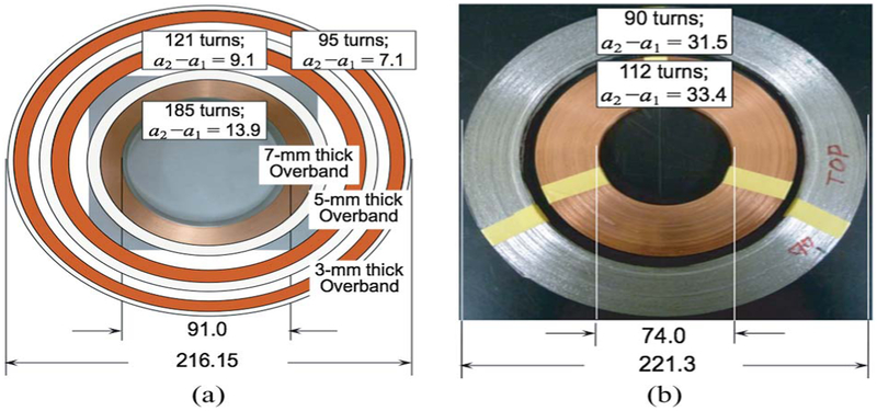
The H800 is compact. As seen from a top view of the H800 three-coil assembly [see Fig. 2(a)], each NI coil has a radial build markedly smaller than those of the H600, whose two-coil top view is shown in Fig. 2(b). This drastic change is not due to leaving out insulation layers, each ~25 μm thick, but removal of a 225-μm-thick copper strip (one side insulated) from the inner coil of H600, necessitated to prevent overheating as the current commutation option, available in NI winding, is unavailable.
Fig. 2.
(a) Three-NI-coil H800: Coil 1 and Coils 2 and 3 (drawings), all 6-mm-wide GdBCO tape. (b) Original two-coil H600 (photo): inner, insulated 4-mm-wide GdBCO tape cowound with 225-μm-thick Cu tape; outer 4.3-mm-wide Bi2223 tape. Dimensions are in millimeters.
Mechanical
Elimination of mechanically weak organic insulation makes each coil a metallic robust entity.
Self-Protecting
When a normal zone appears in an NI coil, the azimuthal current in the coil quickly switches to the adjacent turns to keep the hot spot from overheating: The NI coil is self-protecting. In an L500 quench, when its current decays over a few minutes, H800 is globally driven normal by its induced radial current. Even if the H800 absorbs the entire1.3-G magnetic energy of 6.4 MJ—highly unlikely—it will be heated only to ~280 K. Here, this radial current heats up the built-in resistive elements distributed throughout the NI winding: It benefits protection.
Charging Delay and Circuit Model
When an NI DP coil is energized, because current also flows radially, the coil field trails its supply current, characterized by a charging delay time constant, τd, estimable by an equivalent circuit model. Each jth pancake coil of a DP coil is modeled by a parallel LjRj circuit[14]–[16]. A circuit model for an NI DP coil comprising 2np turns is a 2np-series-connected LjRj circuit. Lj and Rj may be lumped into inductance Ldp and resistance Rdp, where Ldp is the coil inductance, and Rdp is the sum of 2np and Rj [14]–[16]. For an NI magnet of Nm DP coils, its Lm is the magnet inductance, and Rm is the sum of Nm and Rdp. Thus
| (1) |
| (2) |
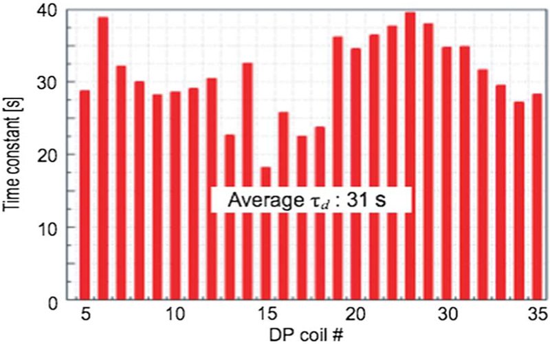
In (1), Rc is the turn-to-turn contact resistivity [Ω m2]. Fig. 3 shows measured τd for 26 DP coils in Coil 1, extracted from the V (I) trace of each DP coil; Coil 1 DP coils have an average Ωd of 31 s. With an average self-inductance of 21 mH for these DP coils, we compute Rm =26 × (21 mH/31 s)=17.6 mΩ, or from (1) Rc =35 μΩ cm2, agreeing with those of other GdBCO pancakes [13], and τm =138 s [(2)] for Coil 1. For Coils 2 and 3, we use the same Rc =35 μΩ cm2 and apply (1) and (2) to compute Rm and τm—see Table III for Nm, np, lm. Computed Rm and τm for Coils 2 and 3 are, respectively, 9.1 and 6.1 mΩ, and 624 and 603 s. We estimate that it will take ~1 h to energize H800 to 251.3 A.
Fig. 3.
τd for Coil 1 26 DP coils.
V. HTS SHIMS: Z1, Z2, X, Y FOR 1.3 G
For a shim placed outside of an HTS magnet, apart from being at a great distance from the magnet center, more crucially, its field is attenuated and distorted by the diamagnetic wall of the magnet [20]. Because H800 represents a diamagnetic wall, superconducting shims must be placed in annular space inside its Coil 1 bore, where the field is 30.5 T: Only shims of HTS and a thin radial build are viable. We have developed such HTS shims cut from a wide (currently 46 mm and later 100 mm for 1.3 G) YBCO tape, 80-μm-thick overall with a 1-μm-thick YBCO film.
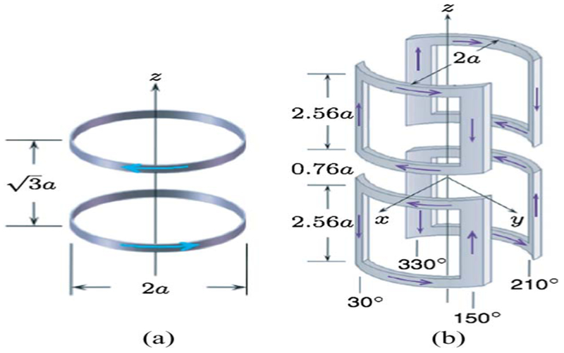
Primarily due to very limited space available to these thin HTS shims (each ~1-mm overall thick), they are not expected to be the only field shimming technique to make this 1.3 G of high resolution. The HTS shims, instead, are to complement conventional RT and ferromagnetic shims. In addition, because they themselves generate error fields, they must be optimized to enhance its benefits and minimize their error field. Fig. 4 shows drawings of ideal (zero thickness) Z1 (a) and X (b) shims, possible with wide YBCO tape. The drawings show proper dimensions in terms of the shim radius, i.e., a. The 1.3 G will have Z1, Z2, X, Y shims in the radius range of 41–43 mm, i.e., each with a 1-mm radial build.
Fig. 4.
Ideal (a) Z1 and (b) X shims.
VI. “SHAKING” MAGNET FOR 1.3 G
For a > 1-GHz NMR magnet, similar to our 1.3 G, that must incorporate an HTS insert, SCF, equivalent to magnetization, is a major error field [7], [29], [30]. Although SCF error field is much less serious with LTS magnets than with HTS magnets, a remedy to remove an SCF error field, proposed in 1982 for LTS magnets [21]–[23], also applies to HTS magnet [24]–[28]. The largest SCF error field occurs in the top and bottom end regions of a magnet, where the radial fields, applied and self field, are greatest, and the effective superconductor size approaches the tape width, i.e., 6 mm for H800. The ± screening currents flow in the ± azimuthal directions, separated ± by the tape width. The basic idea is to apply a small time-varying ± axial field, and repeatedly (“shake”) force the SC in the radial ± directions, gradually de-pin and wipe out the SCF [26]. Using this shaking field technique, we performed an experiment [33] to confirm that the technique would be applicable to reduce SCF error fields from H800. Fig. 5 shows a shaking field time function, i.e., Bsh(t), which is a series of full triangle waves.
Fig. 5.
Time function of shaking magnetic field.
The key important results from our experiment are that SCF error field at the magnet center decreases with 1) the number of cycles and 2) Bsh amplitude. Equally important is that this decrease in SCF error field is not due to ac losses. We demonstrated this important independence on ac losses by varying shaking field frequency and showing that for a given Bsh amplitude, the error field decreases only with the number of cycles.
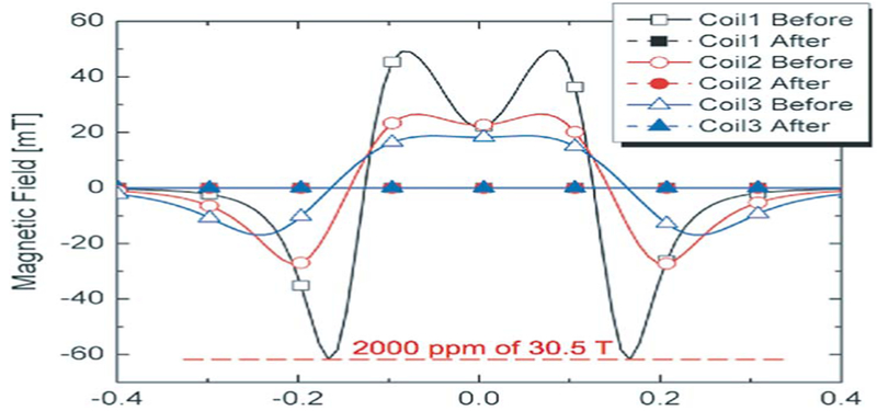
Table IV lists key parameters of a shaking magnet for 1.3 G. The shaking magnet will be wound with Bi2223/stainless-steel tape, overall 4.3 mm wide and 0.31 mm thick, manufactured by Sumitomo Electric. Fig. 6 shows computed SCF axial field versus axial distance plots from Coils 1–3 at 30.5 T, before and after a shaking field of 60 mT is applied. Although an amplitude of 60 mT (by Coil 1) is 2000 ppm of 30.5 T, because the SCF fields are symmetric about the midplane, their contributions to error fields are zero. However, in reality, a 2000-ppm raw SCF field may generate an error field of ~200 ppm, which may be wiped out by a shaking field of 60 mT, resulting in a total SCF-error field of ~20 ppm. For the NI H800, a full triangular wave period will be 4 h (four ramps, each 1 h long). For 100 cycles, a shaking period will last 400 h or ~17 days.
TABLE IV.
KEY PARAMETERS OF SHAKING MAGNET FOR 1.3 G
| M | C1 | C2 | C3 | C4 | ||
|---|---|---|---|---|---|---|
| Winding 2α1 (i.d.) | [mm] | 600 | ||||
| Winding 2α2 (o.d.) | [mm] | 602.1 | 600.7 | 603.5 | 600.7 | 600.7 |
| b1 | [mm] | −48.3 | 48.3 | 108.2 | 158.9 | 320.0 |
| b2 | [mm] | 48.3 | 108.2 | 158.9 | 320.0 | 407.5 |
| # turns/layer; # layers | 21; 3 | 13; 1 | 11; 5 | 35;1 | 19;9 | |
| Total conductor length | [m] | 1160 | ||||
| Magnet inductance | [mH] | 126 | ||||
| Bsh @Iop = 98 A | [mT] | 60 | ||||
| Bsh field error @Iop | [%] | < 0.3(500-mm DSV) | ||||
| One wave cycle period | [hr] | 4(=1↑+1↓+l↑+1↓) | ||||
| Shaking period | [day] | ~17 [= (4 hr/cycle) × 100 cycles] | ||||
Fig. 6.
Computed axial Coils 1–3 SCF plots versus axial distance at 30.5 T before and after a ±60-mT shaking field (see Table IV).
VII. OVERALL FIELD SHIMMING FOR 1.3 G
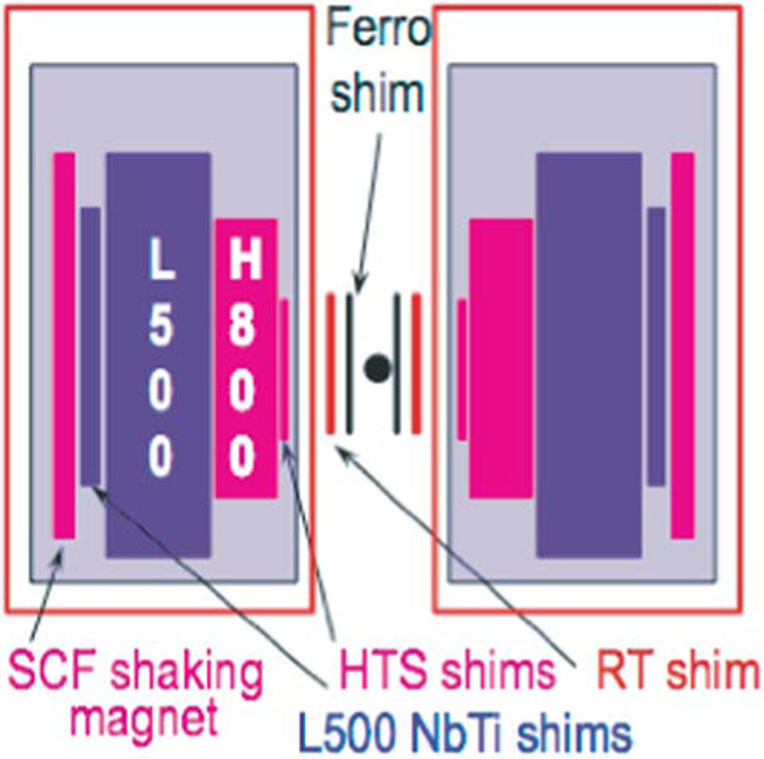
Fig. 7 shows a schematic drawing of a field shimming strategy to be deployed to 1.3 G to make its field suitable for a high-resolution NMR magnet. The LTS (NbTi) shims are built into L500 and make L500 by itself of high resolution. The SCF shaking magnet cuts down the H800 SCF error fields to ~20 ppm. Next, the persistent-mode HTS shims (Z1, Z2, X, Y) will bring it to < 10 ppm. Final shimming will be achieved with a combination of RT shims and ferro shims, making 1.3 G of high resolution, i.e., error fields < 0.1 ppm over a 10-mm DSV.
Fig. 7.
1.3 G field shimming.
VIII. TEMPORAL FIELD STABILITY
The H800 will be in driven mode, powered by a stable supply. A frequency-locking field-stabilizing technique enabled a driven-mode NMR magnet [34] achieve a temporal field stability of < 0.1 ppm/h; it will be applied to our 1.3 G.
IX. 4.2-K OPERATION OF H800 COIL 1
Coil 1 of H800 was assembled with 25 splices between adjacent pancakes. Fig. 8 shows a photo of Coil 1 before each pancake was overbanded. It was operated at 77 and 4.2 K. To generate a design field of 8.646 T, the coil required a current of 253 A, slightly greater than a design current of 251.3 A. At 4.2 K, the critical currents of 26 DP coils were above 253 A. An average joint resistance at 4.2 K of 26.3 nΩ is nearly half that expected [41]. There seems to be no correlation in resistances between 77 and 4.2 K.
Fig. 8.
Photo of Coil 1 before overbanded.
X. CONCLUSION
A key component of a 1.3-GHz/54-mm LTS/HTS NMR magnet (1.3 G) is an 800-MHz GdBCO insert (H800) comprising 96 NI DP coils. The innovative designs, some of their features, and preliminary results presented here and incorporated for the very first time in this high-field HTS insert—NI winding technique; inside-notch pancakes; persistent-mode HTS shims; shaking magnet—promise to make 1.3 G a high-resolution NMR magnet. Note that 1.3 G more than any other > 1-GHz LTS/HTS NMR magnets now under development takes advantage of the enabling technology of HTS. Its share, by H800, is 61.5% of 30.5 T. We believe that this trend of an HTS insert doing more heavy lifting in the future > 1.3 GHz NMR magnets is inevitable. Thus, it is more critical to further develop innovative field-shimming techniques, some of which, to be applied to 1.3 G, were reported here.
ACKNOWLEDGMENT
The authors would like to thank G. V. Gettliffe (Massachusetts Institute of Technology) and the Francis Bitter Magnet Laboratory visiting scientists, Dr. Y. Chu (National Fusion Research Institute, South Korea), and Prof. D. Miyagi (Tohoku University, Japan) for contributing to the shaking-magnet experiment. They would also like to thank J. Colque and P. Allen for their assistance and the AMSC for the supply of wide YBCO tape.
This work was supported in part by the National Institute of Biomedical Imaging and Bioengineering (NIBIB) and in part by the National Institute of General Medical Sciences (NIGMS).
REFERENCES
- [1].Wagner G, Harvard Medical School, private communication, 2008, 2014. [Google Scholar]
- [2].Griffin RG, MIT, private communication, 2008. [Google Scholar]
- [3].Iwasa Y, “Low and high temperature superconducting NMR magnet,” R01-RR15034-01, 1999, NIH. [Google Scholar]
- [4].Bascuñán J, Bobrov E, Lee H, and Iwasa Y, “A low/high-temperature superconducting (LTS/HTS) NMR magnet: Design and performance results,” IEEE Trans. Appl. Supercond, vol. 13, no. 2, pp. 1550–1553, June 2003. [Google Scholar]
- [5].Lee H, Bascuñán J, and Iwasa Y, “A high-temperature superconducting (HTS) insert comprised of double pancakes for an NMR magnet,” IEEE Trans. Appl. Supercond, vol. 13, no. 2, pp. 1546–1549, June 2003. [Google Scholar]
- [6].Bascuñán J et al. , “An LTS/HTS NMR Magnet Operated in the range 600–700 MHz,” IEEE Trans. Appl. Supercond, vol. 17, no. 2, pp. 1446–1449, June 2007. [Google Scholar]
- [7].Hahn S et al. , “Field mapping, NMR lineshape, screening currents induced field analyses for homogeneity improvement in LTS/HTS NMR magnets,” IEEE Trans. Appl. Supercond, vol. 18, no. 2, pp. 856–859, June 2008. [DOI] [PMC free article] [PubMed] [Google Scholar]
- [8].Hahn S et al. , “Development of a 700 MHz low-/high-temperature superconductor for nuclear magnetic resonance magnet: Test results and spatial homogeneity improvement,” Rev. Sci. Instrum, vol. 79, no. 2, February 2008, Art. ID. 26105. [DOI] [PMC free article] [PubMed] [Google Scholar]
- [9].Hahn S et al. , “Operation and performance analyses of 350 and 700 MHz low-/high-temperature superconductor nuclear magnetic resonance magnets: A march toward operating frequencies above 1 GHz,”J. Appl. Phys, vol. 105, no. 2, January 2009, Art. ID. 024501. [Google Scholar]
- [10].Hahn S, Bascuñán J, Yao W, and Iwasa Y, “Two HTS Options for a 600 MHz Insert of a 1.3 GHz LTS/HTS NMR Magnet: YBCO and BSCCO,” Phys. C Supercond, vol. 470, no. 20, pp. 1721–1726, November 2010. [DOI] [PMC free article] [PubMed] [Google Scholar]
- [11].Bascuñán J, Hahn S, Park DK, Kim Y, and Iwasa Y, “On the 600 MHz HTS insert for a 1.3 GHz NMR magnet,” IEEE Trans. Appl. Supercond, vol. 22, no. 3, June 2012, Art. ID. 4302104. [DOI] [PMC free article] [PubMed] [Google Scholar]
- [12].Bascuñán J, Hahn S, Kim Y, and Iwasa Y, “A new high-temperature superconducting (HTS) 700-MHz insert magnet for a 1.3-GHz LTS/HTS NMR magnet,” IEEE Trans. Appl. Supercond, vol. 23, no. 3, June 2013, Art. ID. 4400304. [DOI] [PMC free article] [PubMed] [Google Scholar]
- [13].Bascuñán J, Hahn S, Kim Y, Song J, and Iwasa Y, “18.8-T/90-mm All-GdBCO insert for a 1.3 GHz LTS/HTS NMR magnet: Design and double-pancake coil fabrication,” IEEE Trans. Appl. Supercond, vol. 24, no. 3, June 2014, Art. ID. 4300904. [DOI] [PMC free article] [PubMed] [Google Scholar]
- [14].Hahn S, Park DK, Bascuñán J, and Iwasa Y, “HTS pancake coils without turn-to-turn insulation,” IEEE Trans. Appl. Supercond, vol. 21, no. 3, pp. 1592–1595, June 2011. [DOI] [PMC free article] [PubMed] [Google Scholar]
- [15].Hahn S, Park DK, Voccio J, Bascuñán J, and Iwasa Y, “No-insulation (NI) HTS inserts for > 1 GHz LTS/HTS NMR magnets,” IEEE Trans. Appl. Supercond, vol. 22, no. 3, June 2012, Art. ID. 4302405. [DOI] [PMC free article] [PubMed] [Google Scholar]
- [16].Wang X et al. , “Turn-to-turn contact characteristics for an equivalent circuit model of no-insulation Re[RE]BCO pancake coil,” Supercond. Sci. Technol, vol. 26, no. 3, 2013, Art. ID. 035012. [DOI] [PMC free article] [PubMed] [Google Scholar]
- [17].Hahn S et al. , “No-insulation coil under time-varying conditions: Charging delay and magnetic coupling,” IEEE Trans. Appl. Supercond, vol. 23, no. 3, June 2013, Art. ID. 4601705. [DOI] [PMC free article] [PubMed] [Google Scholar]
- [18].Hahn S et al. , “No-insulation multi-width winding technique for high temperature superconducting magnet,” Appl. Phys. Lett, vol. 103, no. 17, October 2013, Art. ID. 173511. [DOI] [PMC free article] [PubMed] [Google Scholar]
- [19].Iwasa Y, Case Studies in Superconducting Magnet, 2nd ed. New York, NY, USA: Springer-Verlag, 2009. [Google Scholar]
- [20].Iwasa Y et al. , “Persistent-mode high-temperature superconductor shim coils: A design concept and experimental results of a prototype Z1 high-temperature superconductor shim,” Appl. Phys. Lett, vol. 103, no. 5, July 2013, Art. ID. 052607. [DOI] [PMC free article] [PubMed] [Google Scholar]
- [21].Funaki K and Yamafuji K, “Abnormal transverse-field effects in nonideal type II superconductor I. A linear array of monofilamentary wires,” Jpn. J. Appl. Phys, vol. 21, no. 2, pp. 299–304, 1982. [Google Scholar]
- [22].Funaki K, Nidome T, and Yamafuji K, “Abnormal transverse-field effects in nonideal type II superconductor II. Influence of dimension ratios in a superconducting ribbon,” Jpn. J. Appl. Phys, vol. 21, no. 8, pp. 1121–1126, August 1982. [Google Scholar]
- [23].Funaki K, Noda M, and Yamafuji K, “Abnormal transverse-field effects in nonideal type II superconductor III. A theory for an AC-induced decrease in the semi-quasistatic magnetization parallel to a DC bias field,” Jpn. J. Appl. Phys, vol. 21, no. 11, pp. 1580–1587, November 1982. [Google Scholar]
- [24].Brandt EH and Mikitik GP, “Why an ac magnetic field shifts the irreversibility line in type-II superconductors,” Phys. Rev. Lett, vol. 89, no. 2, June 2002, Art. ID. 027002. [DOI] [PubMed] [Google Scholar]
- [25].Mikitik GP and Brandt EH, “Theory of the longitudinal vortex-shaking effect in superconducting strips,” Phys. Rev, vol. B67, no. 10, March 2003, Art. ID. 104511. [Google Scholar]
- [26].Brandt EH and Mikitik GP, “Shaking of the critical state by a small transverse ac field can cause rapid relaxation in superconductors,” Super-cond. Sci. Technol, vol. 17, no. 2, pp. S1–1–S1–4, February 2004. [Google Scholar]
- [27].Kajikawa K and Funaki K, “A simple method to eliminate shielding currents for magnetization perpendicular to superconducting tapes wound into coils,” Supercond. Sci. Technol, vol. 24, no. 12, December 2011, Art. ID. 125005. [Google Scholar]
- [28].Kajikawa K and Funaki K, “Reduction of magnetization in windings composed of HTS tapes,” IEEE Trans. Appl. Supercond, vol. 22, no. 3, June 2012, Art. ID. 4400404. [Google Scholar]
- [29].Gu C, Qu T, and Han Z, “Measurement and calculation of residual magnetic field in a Bi2223/Ag Magnet,” IEEE Trans. Appl. Supercond, vol. 17, no. 2, pp. 2394–2397, June 2007. [Google Scholar]
- [30].Amemiya N and Akachi K, “Magnetic field generated by shielding current in high Tc superconducting coils for NMR magnets,” Supercond. Sci. Technol, vol. 21, no. 9, September 2008, Art. ID. 095001. [Google Scholar]
- [31].Ahn MC et al. , “Spatial and temporal variations of a screening current induced magnetic field in a double-pancake HTS insert of an LTS/HTS NMR magnet,” IEEE Tran. Appl. Supercond, vol. 19, no. 3, pp. 2269–2272, June 2009. [DOI] [PMC free article] [PubMed] [Google Scholar]
- [32].Yanagisawa Y et al. , “Effect of YBCO-coil shape on the screening current-induced magnetic field intensity,” IEEE Trans. Appl. Supercond, vol. 20, no. 3, pp. 744–747, June 2010. [Google Scholar]
- [33].Kajikawa K et al. , “Design and tests of compensation coils to reduce screening currents induced in HTS coil for NMR magnet,” presented at the 23rd Int. Conf. Magnet Technol, Boston, MA, USA, July 2013. [Google Scholar]
- [34].Yanagisawa Y et al. , “Operation of a 500 MHz high temperature superconducting NMR: Towards an NMR spectrometer operating beyond 1 GHz,” J. Magn. Resonance, vol. 203, no. 2, pp. 274–282, April 2010. [DOI] [PubMed] [Google Scholar]
- [35].Bascuñán J, Hahn S, Ahn M, and Iwasa Y, “Construction and test of a 500 MHz/200 mm RT bore solid cryogen cooled Nb3Sn MRI magnet,” Adv. Cryogenic Technol, vol. 55A, pp. 523–530, April 2010. [Google Scholar]
- [36].Kasaba K et al. , “Stress/strain dependence of critical current in Nb3 Sn superconducting wires stabilized with CuNb microcomposites—Effect of Nb content,” Cryogenics, vol. 41, no. 1, pp. 9–14, January 2001. [Google Scholar]
- [37].Lu J, Choi ES, and Zhou HD, “Physical properties of Hastelloy c – 267™ at cryogenic temperatures,” J. Appl. Phys, vol. 103, no. 6, March 2008, Art. ID. 064908 [Google Scholar]
- [38].Reed RP and Clark AF, Materials at Low Temperatures. Metals Park, OH, USA: American Society for Metals, 1983. [Google Scholar]
- [39].Hazelton D, “Application of SuperPower 2 G HTS wire to high field devices,” presented at the 22nd Int. Conf. Magnet Technol, Marseille, France, September 12–16, 2011. [Google Scholar]
- [40]. [Online]. Available: hhtp:/www.k-mac-plastics.net/data%20sheets/fiberglass_technical_data.htm
- [41].Lécrevisse T et al. , “Pancake–pancake joint resistances of a magnet assembled from GdBCO double-pancake coils,” presented at the 23rd Int. Conf. Magnet Technol., Boston, MA, USA, July 14–19, 2013. [Google Scholar]


