Abstract
This paper deals with the latest design of an all High Temperature Superconductor (HTS) insert for our 1.3 GHz NMR program. Due to a loss of our original 600 MHz HTS insert, the entire program was revised, and upon further examination of the options available for the HTS insert, which included not only conductor material properties, but also new winding technologies recently developed here at the FBML, it has finally been decided to build an 800 MHz (H800) insert purely based in SuperPower YBCO conductor. The new H800 will still be comprised of nested stacks of double-pancake coils and will run in the background of a 500 MHz LTS NMR magnet already available at FBML. We present here electromagnetic and mechanical details of the H800 design, winding technique employed, and testing of individual coils.
Keywords: Double-pancake (DP) coils, high temperature superconducting (HTS) insert, NMR, superconducting magnet, YBCO
I. INTRODUCTION
THE MAIN goal of our program, 1.3 GHz NMR magnet was originally conceived as composed of a 700 MHz LTS NMR quality background coil and a 600 MHz HTS insert coil; however, the unexpected loss of our 600 MHz HTS insert coil [1] has provided us with an opportunity to examine more closely the available options for a new all HTS insert coil, considering latest conductor material properties and winding schemes. It has also allowed us to, from the economic point of view, to make a better selection of the LTS + HTS combination.
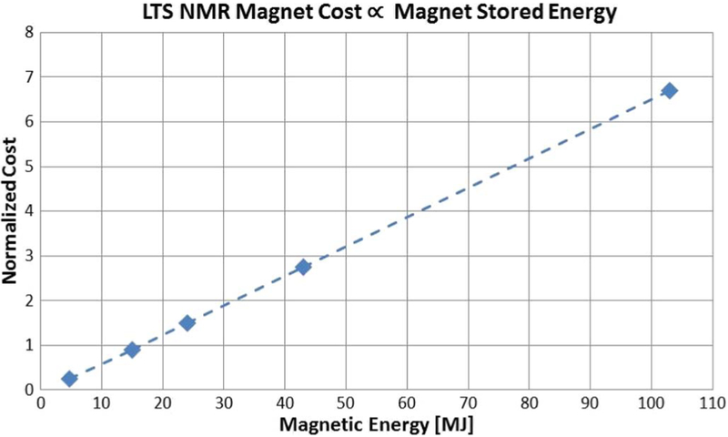
Several such combinations were considered, but realizing that the cost of an LTS NMR magnet, the largest cost driver of the LTS/HTS magnet system, is as shown in Fig. 1, essentially directly proportional to its stored energy [2] and also considering the mechanical and electrical capabilities of available high temperature superconductors, the chosen combination was of a MHz LTS NMR magnet (L500) + 800 MHz (18.8 T) HTS insert coil (H800). The HTS insert is based purely on YBCO conductor fabricated by SuperPower.
Fig. 1.
Graph showing the relationship between a magnet cost and its stored magnetic energy [2].
II. 90 mm/18.8 T ALL (RE)BCO INSERT MAGNET
A. Conductor
As stated above, the conductor of choice for the H800 is SuperPower’s 2G HTS (RE)BCO wire Type SCS6050-AP. Conductor specifications are listed in Table I. This conductor being 6 mm wide as opposed to the 4 mm wide used in our original 600 MHz HTS insert introduces, although not significant, an increase in screening currents, a factor already considered in the new HTS insert design presented here.
TABLE I.
CONDUCTOR SPECIFICATIONS (MANUFACTURER PROVIDED)
| Superpower (RE)BCO Type SCS6050-AP Wire | |
|---|---|
| Width | 6.1 mm +/− 0.15 mm |
| Thickness | ~ 0.075 mm + 0.025 mm/−0.01 mm |
| Ic (77 K, self-field) | minimum value of 165 A |
| Copper stabilizer thickness | 0.02 mm +/− 0.01 mm (10 μm per side) |
| Silver overlayer thickness | 2.0 μm +/− 0.5 μm |
| Hastelloy substrate thickness | 0.05 mm |
| Critical tensile stress | > 550 MPa |
B. Coils
The H800 consists of double pancakes (DP) wound dry with no inter-turn insulation, its purpose being that in the event of a quench, the current will automatically bypass the hot spot through turn-to-turn contacts rather than following the winding spiral path, thus making the H800 self-protecting. Additionally, the no inter-turn insulation makes each DP, and therefore the entire insert more compact and robust. The coils do however have a layer of thin G-10 providing inter-pancake and inter-DP insulation. The no inter-turn insulation or no-insulation (NI) winding technique for high temperature superconducting (HTS) magnet was proposed by the Francis Bitter Magnet Laboratory in 2011 [3], technique that to date has been embraced by several research groups [4], [5].
In the design stages, a stress analysis of the H800 operating in the background of the all-LTS 500 MHz NMR magnet, indicated that the H800 should consists of 3 coils, nested together, in order to cope with the high stresses developed during the magnet system operation. Considering only winding and energizing of the coils, stresses and strains were computed by force equilibrium and generalized Hooke’s laws under the plane strain assumption.
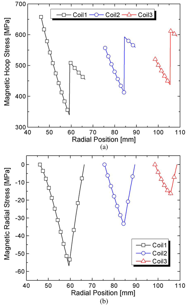
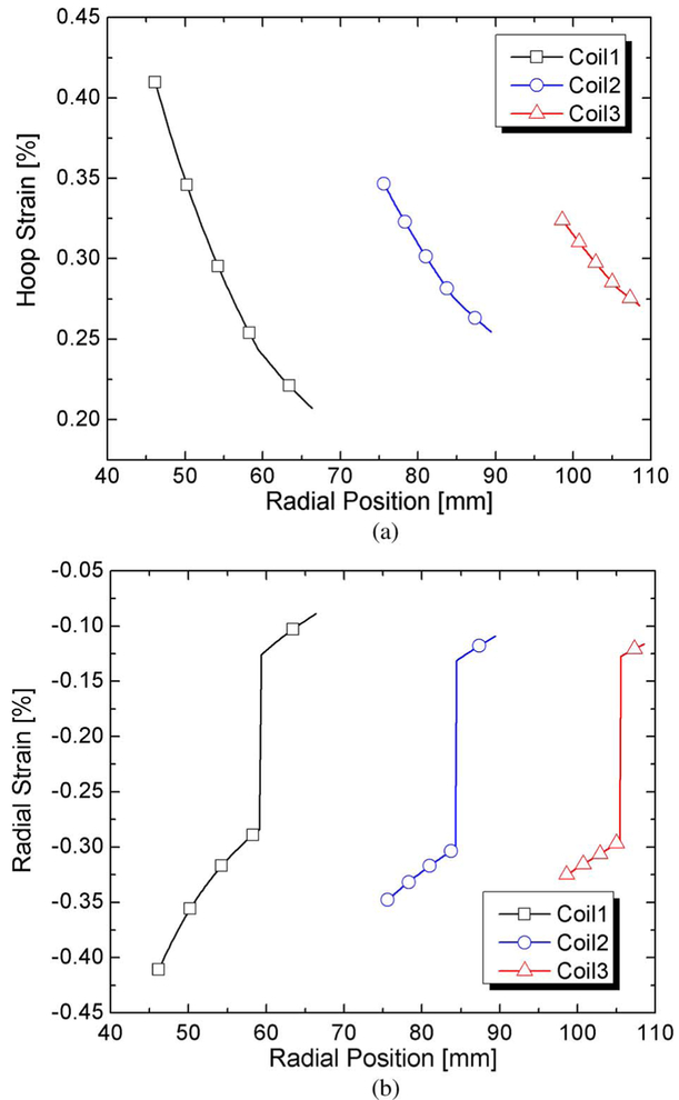
Considering not only the stresses, but the strains developed during operation of the magnet system, each DP also includes an overbanding. The overband is made of nonmagnetic stainless steel tape wound under a tension that will render the radial stresses compressive, thus aiding in reducing the coil hoop stresses. The magnetic hoop and radial stresses, to which each coil will be subjected while in operation together with the L500, are shown in Fig. 2, where the effect of the overbanding is included. Calculated hoop and radial strains are presented in Fig. 3. The jumps in the traces of Figs. 2 and 3 correspond to the transition from coil to overbanding. The key parameters of the H800 are presented in Table II.
Fig. 2.
Computed (a) hoop and (b) radial stresses of H800 in the background of L500. The origin (radial position = 0) is center of coil.
Fig. 3.
Computed strains, (a) hoop and (b) radial, of H800 in the background of L500. The origin (radial position = 0) is center of coil.
TABLE II.
HTS INSERT (800 MHz) KEY PARAMETERS (AS DESIGNED)
| Coil 1 | Coil 2 | Coil 3 | |
|---|---|---|---|
| GENERAL | |||
| Conductor | YBCO | YBCO | YBCO |
| Frequency, MHz | 371 | 241 | 188 |
| Field contribution, T | 8.72 | 5.65 | 4.42 |
| Peak B⊥, T | 4.77 | 4.61 | 3.73 |
| Operating temperature, K | 4.2 | ||
| Operating current, A | 250.0 | ||
| Current density, A/mm2 | 544.04 | ||
| Total number of DPs | 26 | 32 | 38 |
| Outer diameter, mm | 118.75 | 168.90 | 211.15 |
| Overall height, mm | 318.60 | 392.13 | 465.65 |
| SS overbanding, mm | 7 | 5 | 3 |
| Total inductance, H | 20.82 | ||
| Total wire, km | 3.14 | 3.84 | 4.61 |
| Winding tension, kg | 5 | 5 | 5 |
| FULL PANCAKES | |||
| Turns per pancake | 185 | 121 | 95 |
| Inner diameter, mm | 91.00 | 150.75 | 196.90 |
| Wire/DP, m | 120.7 | 120.7 | 121.2 |
| Height, mm | 318.60 | 392.13 | 465.65 |
| NOTCHED DPs | |||
| Number of notched DPs | 6 | 10 | 8 |
| Turns per pancake | 176 | 118 | 93 |
| Inner diameter, mm | 92.35 | 151.20 | 197.20 |
| Wire/DP, m | 115.6 | 118.9 | 118.7 |
| Notch height, mm | 75.32 | 122.54 | 98.03 |
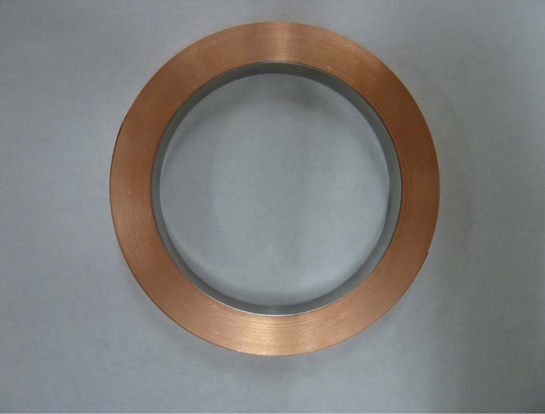
During the winding of the first DP, it was found that the innermost layers of the coil would collapse upon its removal from the mandrel. A calculation, treating the innermost layer of the DP as a pressure vessel under external pressure, indicated that the pressure developed during winding was indeed enough to collapse the “thin walled pressure vessel”. To prevent the collapsing, each coil will be fitted with a thin nonmagnetic inner stainless steel support ring. Shown in Fig. 4 is a DP with its stainless steel ring on its ID. Another feature of the H800 is the use of a technique routinely used in NMR and MRI magnets to improve the field homogeneity, namely the introduction of notched coils in the system [6], albeit here the notches are placed inside the coil rather than outside as it is customarily done in the previously mentioned units.
Fig. 4.
Photograph of a completed DP coil showing the internal nonmagnetic stainless steel support ring.
As noted in Table III, all DPs of anyone coil have the same OD, but different IDs depending upon if they have or not an inside notch. In order to make the stack assembly of the same ID, thicker inner supporting rings are used for the notched DPs, with the added benefit that they prevent the innermost layers of the DPs above and below the notch to move due to axial loading during operation.
TABLE III.
SUMMARY OF TEST RESULTS
| No notch DP |
Notched DP |
|
|---|---|---|
| Critical current, Ic [A] | 75 | 66 |
| Characteristic resistance, Rc [μΩ] | 1200 | 700.1 |
| Inductance, L [mH] | 20.3 | 19.1 |
| Time constant, τc [s] | 16.92 | 27.28 |
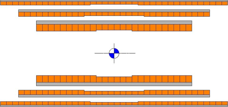
The notches are depicted schematically in Fig. 5, in a to-scale cross-sectional view of the three coils composing the 800 MHz HTS insert. Not shown are the inner stainless steel supporting rings. Also, not shown are the centering inner tubes that will allow each coil to be assembled with its required preload.
Fig. 5.
To-scale schematics of the three coils that make the 800 MHz (18.8 T) all HTS insert magnet. Gray hatch depicts the overbanding. Coils are shown horizontally for clarity purposes. The full NMR magnet system is in the vertical orientation.
III. DOUBLE-PANCAKE COIL TESTING
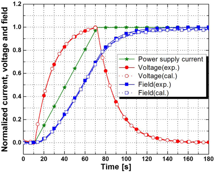
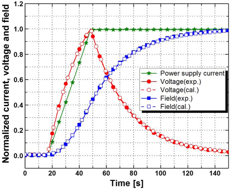
In order to investigate performance of the coils that would be making up the H800, two DPs, one corresponding to an un-notched, the other to a notched coil, were tested in a bath of LN2 by charging them to a target current at a rate of 10 A/min, and then holding the current at that level for approximately 2 minutes. Of particular interest was to observe/determine the charging delay that naturally occurs in a no-insulation coil, delay due to the fact that the current bypasses the spiral path through turn-to-turn contacts within the coil.
The coils were instrumented with voltage taps and a Hall sensor with a sensitivity of 0.2 V/T at 77 K.
Plots of a charging test are presented in Figs. 6 and 7, for the un-notched DP and for the notched DP, respectively.
Fig. 6.
Normalized power supply current, voltage, and field for a DP without a notch. The closed and opened symbols indicate the experimental and calculated values, respectively.
Fig. 7.
Normalized power supply current, voltage, and field for a notched DP. The closed and opened symbols indicate the experimental and calculated values, respectively.
To obtain charging time constant (Tc), characteristic resistance (Rc) considered to be the sum of all resistances of all resistance in the noninsulated coil was calculated firstly in this study [7], [8]. The Rc was determined following three step [9]: 1) charge the no-insulated coil to a target current at a ramping rate of 10 A/min and hold the target current for 120 s; record the power supply current, the voltage and the center field (Bm) for the 120 s; 3) calculate Rc that minimizes (1), where Bc is the calculated center field with a given Rc
| (1) |
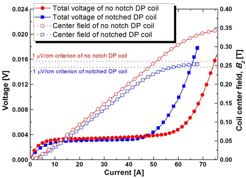
After that, from this result, τc for both coils were determined from τc = L/Rc where L is the DP coil inductance. A summary of the results is presented in Table III, while a plot of voltage versus current shows the critical currents in Fig. 8, Ic of the coils tested using the 1 μV/cm criterion.
Fig. 8.
V –I and magnetic field curves of HTS DP coils in the bath of LN2 at 77 K. Circle and square indicate the no-notch DP coil and notched DP coil, respectively.
IV. 1.3 GHZ MAGNET SYSTEM FINAL ASSEMBLY
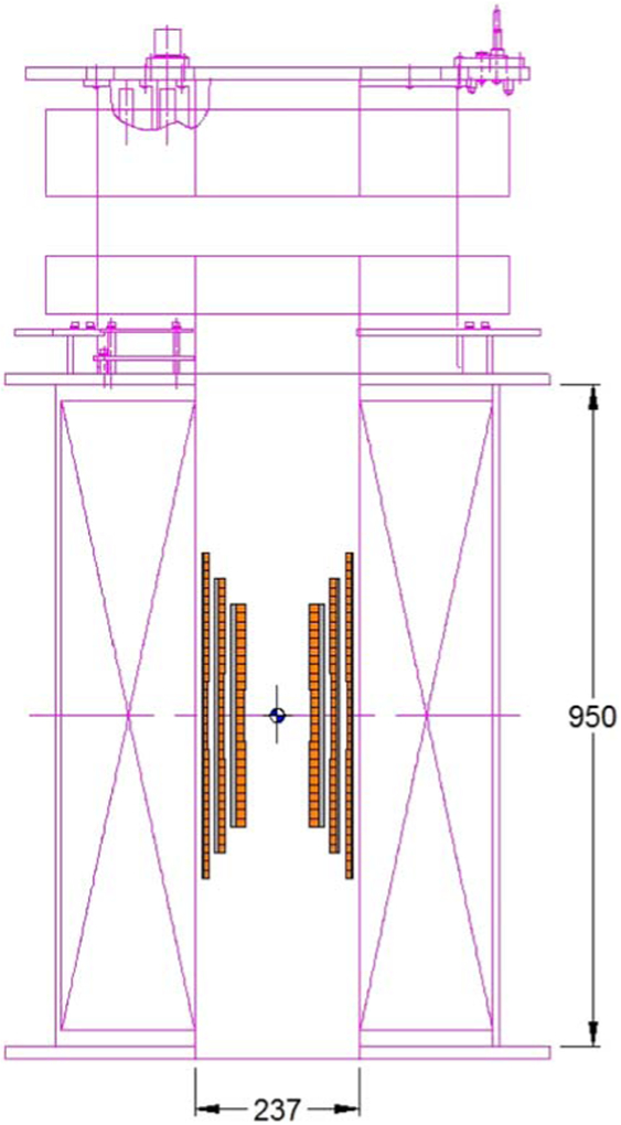
The H800 in its final position in the bore of the L500 is shown, to-scale, in Fig. 9. The H800 will be preassembled as one entity by means of centering tubes which will allow setting the required coil preloads using Belleville washers. The entire H800 assembly will be secure to top and bottom flanges on the L500 (not shown).
Fig. 9.
To-scale representation of the full LTS/HTS 1.3 GHz magnet system.
V. CONCLUSION
We have presented here the design of an entirely new all-HTS 800 MHz insert magnet based on (RE)BCO conductor. Three stacks of DP wound with no inter-turn insulation make the insert. We are in the process of fabricating the innermost coil of which a few DPs have been tested and determined that their time constant is acceptable for NMR magnets.
Acknowledgments
This work was supported by the National Center for Research Resources, the National Institute of Biomedical Imaging and Bioengineering, and the National Institute of General Medical Sciences.
REFERENCES
- [1].Bascuñán J, Hahn S, Kim Y, and Iwasa Y, “A new High-Temperature Superconducting (HTS) 700-MHz insert magnet for a 1.3-GHz LTS/HTS NMR magnet,” IEEE Trans. Appl. Supercond, vol. 23, no. 3, p. 4400304, June 2013. [DOI] [PMC free article] [PubMed] [Google Scholar]
- [2].Yushikawa M, private communication, 2011. [Google Scholar]
- [3].Hahn S, Park FK, Bascuñán J, and Iwasa Y, “HTS pancake coils without turn-to-turn insulation,” IEEE Trans. Appl. Supercond, vol. 21, no. 3, pp. 1592–1595, June 2011. [DOI] [PMC free article] [PubMed] [Google Scholar]
- [4].Kim YG, Hahn S, Kim KL, Kwon OJ, and Lee H, “Investigation of HTS racetrack coil without turn-to-turn insulation for superconducting rotating machines,” IEEE Trans. Appl. Supercond, vol. 22, no. 3, p. 5200604, June 2012. [Google Scholar]
- [5].Choi S, Jo HC, Hwang YJ, Hahn S, and Ko TK, “A study on the no insulation winding method of the HTS coil,” IEEE Trans. Appl. Supercond, vol. 22, no. 3, p. 4904004, June 2012. [Google Scholar]
- [6].Montgomery B and Weggel R, Solenoid Magnet Design Malabra, FL, USA: Frieger Publishing Co., 1980. [Google Scholar]
- [7].Hahn S, Kim Y, Ling J, Voccio J, Park DK, Bascuñán J, Shin HJ, Lee HG, and Iwasa Y,“No-insulation coil under time-varying condition: Magnetic coupling with external coil,” IEEE Trans. Appl. Supercond, vol. 23, no. 3, p. 4601705, June 2013. [DOI] [PMC free article] [PubMed] [Google Scholar]
- [8].Wang X, Hahn S, Kim Y, Bascuñán J, Voccio J, Lee HG, and Iwasa Y, “Turn-to-turn contact characteristics for an equivalent circuit model of no-insulation ReBCO pancake coil,” Supercond. Sci. Technol, vol. 26, no. 3, pp. 035012-1–035012-6, March 2013. [DOI] [PMC free article] [PubMed] [Google Scholar]
- [9].Song JB, Hahn S, Kim Y, Voccio J, Ling J, Bascuñán J, Lee H, and Iwasa Y, “HTS wind power generator: Electromagnetic force between no-insulation and insulation coils under time-varying conditions,” IEEE Trans. Appl. Supercond, to be published. [Google Scholar]


