Abstract
This paper reports a study of HTS pancake coils without turn-to-turn insulation. Three no-insulation (NI) pancake coils were wound: each single and double pancake coil of Bi2223 conductor and one single pancake of ReBCO conductor. An equivalent electrical circuit for modeling NI coils was verified by two sets of test: 1) charge-discharge; and 2) sudden discharge. Also, an overcurrent test in which a current exceeding a coil’s critical current by 2.3 times was performed, and analysed, to demonstrate that in terms of stability NI HTS coils outperform their counterparts. The new NI winding offers HTS coils enhanced performance in three key parameters: overall current density; thermal stability; and mechanical integrity.
Index Terms—: HTS pancake coils, mechanical integrity, no-insulation winding, thermal stability, turn-to-turn-insulation
I. INTRODUCTION
Insulation is considered indispensible to the magnet, superconducting or resistive. In superconducting magnets, various materials have been investigated for insulation [1] but most of them, made of organic materials, are much softer than superconductor, metal stabilizer, and substrate. In consequence, elastic anisotropy effect on mechanical strain increment, the so-called “spongy effect,” is an important issue, particularly in high-field superconducting magnets [2], [3]. In the mid 1980s, even a metallic insulation was suggested and patented to improve mechanical integrity of superconducting magnets [4].
In designing a high-field HTS insert, comprising double-pancake (DP) coils, for our 1.3-GHz NMR magnet [5], one option was no turn-to-turn insulation (NI) DP coils. For the NI option, one relevant question was stability of these NI coils during charging and discharging sequences. Conductor thicknesses of HTS commercially available are typically less 100 μm, roughly equal to those of insulation layers. Elimination of insulation should benefit a magnet, particularly its overall current density, mechanical integrity, and as demonstrated here, its thermal stability.
This paper presents a study of HTS pancake coils without turn-to-turn insulation. Specific aspects of NI pancake coils investigated here include: 1) charge-discharge delay; 2) quench behavior under an over-current condition; and 3) equivalent circuit for NI coils. Three NI pancake coils were wound: each single and double pancake coil of Bi2223 conductor and one single pancake of ReBCO conductor. The proposed equivalent circuit was verified by two sets of test: 1) charge-discharge; and 2) sudden discharge. Also, an overcurrent test in which a current exceeding a coil’s critical current by 2.3 times was performed, and analysed, to demonstrate that in terms of stability NI HTS coils outperform their counterparts.
II. SINGLE PANCAKE COIL TEST
A. Two Test Coils: Bare and Hastelloy
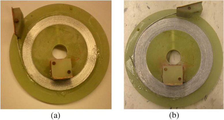
Fig. 1 shows two pictures of single-pancake test coils: a) a bare winding without any insulation (Bare); and b) a winding co-wound with Hastelloy C276 tape (Hastelloy). Table I summarizes parameters of the test coils. Both coils were wound with AMSC’s Bi2223-Ag/SS 3-ply tapes where Bi2223-Ag conductor was sandwiched with two stainless steel strips. Except for the winding outer diameter, the configurations of the two coils are almost identical, resulting in nearly the same center field and inductance. A Hall sensor is placed on a separate G10 plate and positioned at the center of each coil. All tests were performed in a bath of liquid nitrogen at 77 K.
Fig. 1.
Pictures of two single-pancake test coils: (a) bare winding without any insulation (Bare); (b) co-wound with Hastelloy C276 tape (Hastelloy.).
TABLE I.
Parameters of the Two Pancake Test Coils
| Parameters | Bare | Hastelloy | |
|---|---|---|---|
| HTS Conductor | AMSC Bi2223-Ag/SS 3-ply | ||
| Conductor width; thickness | [mm] | 4.1; 0.3 | |
| Ic @ 77 K, self-field | [A] | 106 – 115 | |
| Ic @ 77 K, coil | [A] | 76 | 85 |
| Insulation | bare (no insulation) | Hastelloy C276 | |
| Insulation width; thickness | [mm] | N/A | 4.1; 0.3 |
| # of turns | 30 | 30 | |
| i.d.; o.d.; height | [mm] | 60; 78; 4.1 | 60; 84; 4.1 |
| Bz per amp at center | [mT/A] | 0.55 | 0.53 |
| Inductance | [μH] | 99.6 | 97.5 |
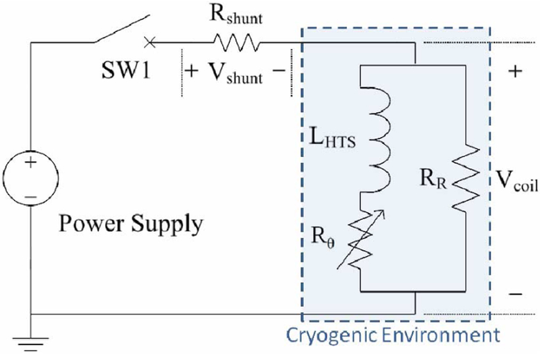
Fig. 2 shows an electrical circuit diagram which consists of a DC power supply, a test coil in cryogenic environment (shaded box with dashed outline), a shunt resistor, and a switch. The anisotropy of the NI coil’s resistance is modeled with three components: LHTS (HTS coil self inductance); Rθ (azimuthal resistance including index loss and matrix resistance of the HTS wire); and RR (radial resistance including contact, insulation, and substrate resistances.)
Fig. 2.
Electrical circuit diagram with a DC power supply, a test coil in cryogenic environment (shaded section), a shunt resistor, and a switch—all connected in series. Three components in the equivalent circuit model of the NI test coil: LHTS (self inductance of HTS winding); Rθ (azimuthal resistance including index loss and matrix resistance of HTS wire); and RR (radial resistance including contact, insulation, and substrate resistances).
B. Test Results and Analyses
1). Charge-Discharge Tests:
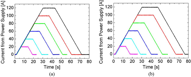
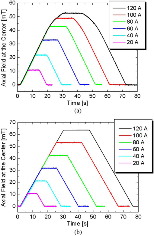
Figs. 3(a) and 3(b) show current supply, in an increment of 20 A, charge-discharge time functions, respectively, through Bare and Hastelloy coils. Fig. 4 presents center field time functions for these coils. In the Bare coil of which critical current is 76 A, the center field increases linearly up to 60 A in the same way of an insulated coil but saturates as 43, 49, and 53 mT at 80, 100, and 120 A, respectively. If insulated, the coil should have produced 66 mT at 120 A, i.e., 20% of the supply current bypassed the original superconducting spiral path through turn-to-turn contacts within the coil. In the Hastelloy coil, the field saturation is hardly observed; at 120 A, the center field is 64 mT as expected for a fully insulated counterpart.
Fig. 3.
Power supply current time functions: (a) Bare and (b) Hastelloy. Each figure contains six individual current profiles from 20 to 120 A at every 20 A.
Fig. 4.
Axial center field time functions: (a) Bare; and (b) Hastelloy.
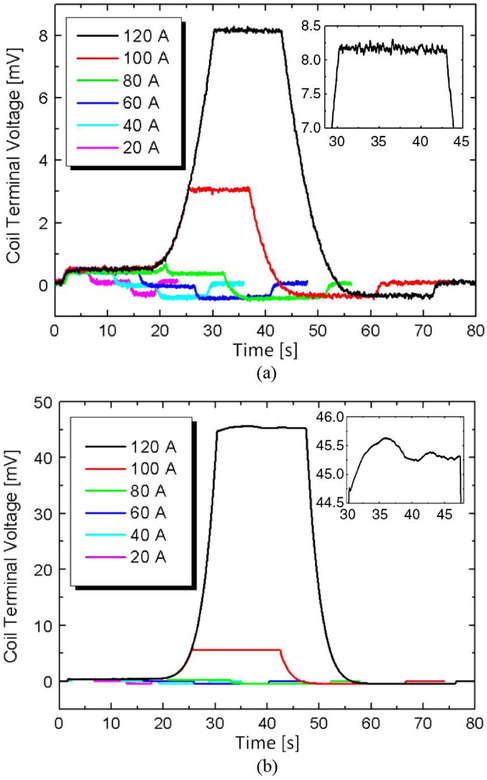
Fig. 5 shows coil terminal voltages. With a 1 μV/cm criterion, the critical current of the Hastelloy coil is 85 A. At 120 A with the power supply in a constant-current mode, current and field were stable in both Bare and Hastelloy coils as seen from Figs. 3 and 4. However, the Hastelloy coil voltage became unstable as 45.0 +/− 0.5 mV [inset graph in Fig. 5(b)], which may imply an overheating-and-recovery phenomenon taking place locally within the winding and a resulting variation in the coil resistance. However, at 120 A the Bare coil voltage was stable at 8.2 mV because of the 20% power supply current bypass.
Fig. 5.
Coil terminal voltage time functions: (a) Bare; (b) Hastelloy. The inset graph in each figure is an enlarged view of the 120-A case.
Sudden Discharge Tests:
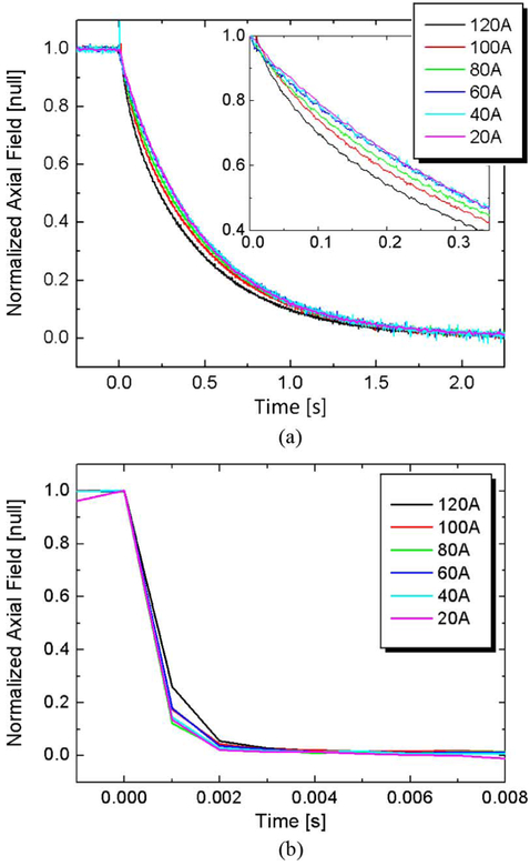
In a sudden discharge test at each current level in Fig. 3, the coil is under steady-state operation before the switch (SW1 in Fig. 2) is opened. Field decay time functions are presented in Fig. 6 in which each field is normalized at its initial value. Two decay time constants, initial (τi) and average (τavg), may be defined, the first as an instant decay constant determined at and the second determined at a normalized field of 0.37. Based on the results shown in Figs. 4–6, (1) and (2) are used to calculate the equivalent circuit parameters of Fig. 2, as summarized in Table II; BM, BC, and IPS are, respectively, measured field, calculated field, and power supply current. Characteristic resistance, RC is defined as a sum of Rθ and RR:
| (1) |
| (2) |
Fig. 6.
Normalized field time functions from sudden discharge tests: (a) Bare;(b) Hastelloy. Time reference of each graph was adjusted for easy comparison.
TABLE II.
Decay Time Constant and Equivalent Circuit Parameters
| Parameters | Bare | Hast. | ||||
|---|---|---|---|---|---|---|
| 60 A | 80 A | 100 A | 120 A | 120 A | ||
| τi | [ms] | 438 | 365 | 317 | 239 | -- |
| τavg | [ms] | 463 | 447 | 420 | 372 | 0.7 |
| BM/BC | 1 | 0.971 | 0.887 | 0.797 | ~1 | |
| Rr | [mΩ] | 0.228 | 0.265 | 0.279 | 0.332 | 139 |
| Rθ | [mΩ] | 0. | 0.008 | 0.035 | 0.084 | 0.375 |
| RC | [mΩ] | 0.228 | 0.273 | 0.314 | 0.416 | 139 |
In the 20–60 A Bare coil tests, the initial and average time constants are barely different (<10%) and Rθ = 0 because the whole coil is superconducting. However, at currents higher than its critical current and decrease as increases because Rθ, representing index and matrix losses, increases as does RR. Note that τavg is larger than τi in general because both Rθ and RR decrease as the coil current decays and the coil cools down to its nominal operating temperature of 77 K.
In Hastelloy coil test [Fig. 6(b)] τavg is smaller than a measurement limit of 1 ms; its estimated value is 0.7 ms at 120 A. Rθ, at 120 A was obtained from a “steady-state” voltage of 45 mV [Fig. 5(b)]: 45 mV/120 A = 0.375 mΩ; it is much smaller than. Note that respective voltages of Bare coil at 100 A and 120 A [from Fig. 6(a)] are 3.2 and 8.2 mV, both of which agree well with 3.1 and 8.0 mV calculated by. (3) from the equivalent circuit. The results imply that the proposed equivalent circuit model and the presented analyses are valid:
| (3) |
III. DOUBLE PANCAKE COIL TEST
A. Double Pancake Test Coil
With the same conductor used for the single pancake coil test, a double-pancake (DP) coil was wound without any insulation, turn-to-turn or pancake-to-pancake. Its parameters are summarized in Table III.
TABLE III.
Parameters of the Double Pancake Test Coil
| Parameters | Values | |
|---|---|---|
| Insulation | bare (no insulation) | |
| # of turns per pancake | 38 | |
| Ic @ 77 K, coil | [A] | 70 |
| i.d.; o.d.; height | [mm] | 78.2; 101.0; 8.3 |
| Bz per ampere at center | [mT/A] | 1.07 |
| Inductance | [mH] | 0.785 |
B. Test Results and Analyses
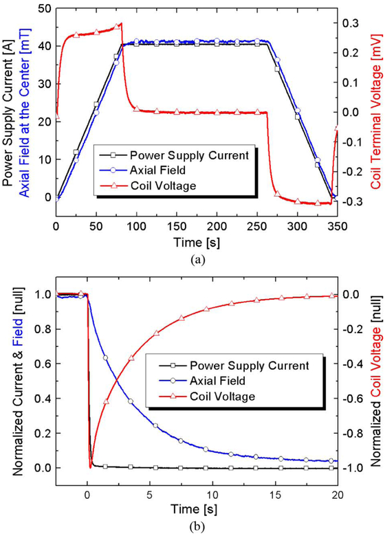
The charge-discharge time functions of the no-insulation DP coil are similar to those of the single pancake coil. Figs. 7(a) and 7(b) show, respectively, the time functions at 40 A of charge-discharge and sudden-discharge tests. Computed RC is 0.281 mΩ with τi of 2.79 s, 6 times larger than τi of the single pancake coil. We believe that this large difference in τi is due to the absence of a pancake-pancake insulation. The absence of a pancake-pancake insulation may make a double-pancake coil like two single pancake coils shorted at its terminals. Further tests are being prepared to investigate this issue.
Fig. 7.
(a) Charge-discharge and (b) sudden discharge test results of the DP coil at 40 A; Black squares: power supply current; blue circles: axial center field; red triangles: coil voltage.
IV. REBCO PANCAKE COIL
A. ReBCO Single Pancake Test Coil
Table IV summarizes parameters of an ReBCO single pancake test coil. Its inner diameter and number of turns are identical to those of the Bi2223 single pancake listed in Table I.
TABLE IV.
Parameters of the Rebco Single Pancake Test Coil
| Parameters | Values | |
|---|---|---|
| HTS Conducotr | Super Power SCS4050 | |
| Conductor width; thickness | [mm] | 4.0; 0.1 |
| Copper stabilizer thickness | [mm] | 0.04 |
| Ic @ 77 K, self-field | [A] | 85 |
| Ic @ 77 K, coil | [A] | 54 |
| Insulation | bare (no insulation) | |
| # of turns | 30 | |
| i.d.; o.d.; height | [mm] | 60; 66; 4.0 |
| Bz per amp at center | [mT/A] | 0.60 |
| Inductance | [μH] | 110.0 |
B. Over Current Test
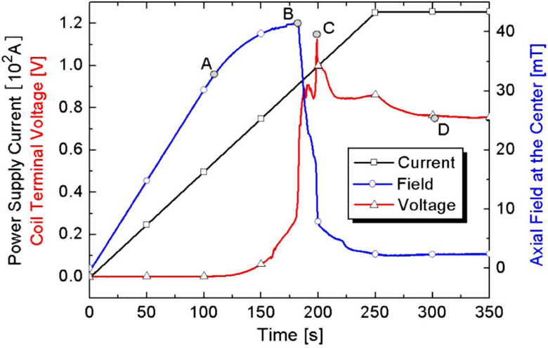
From the charge-discharge time functions, in a same way to those of the Bi2223 test coil, RR was computed as 0.35 mΩ at currents below its critical current, 54 A. Here, we present only an overcurrent test result (Fig. 8) in which the operating current to critical current ratio was 2.3. Black squares are the power supply current, blue circles the axial center field, and red triangles the coil voltage. At point “A” (critical current) the axial field starts saturating. At point “B” the axial center field suddenly starts decreasing and reaches 10 mT in 12 s at point “C.” At point “D”, the coil entered a “steady-state” condition with 0.76 V and 2.3 mT, i.e., 121 A out of 125 A from the power supply current “automatically” bypassed its original spiral path through turn-to-turn contact. For comparison, a short sample test of the same conductor with a layer of 40-μm thick Kapton insulation was separately performed. The test sample was burned out at 110 A, at an operating current to critical current ratio of 1.3. This overcurrent experiment demonstrates that an NI winding may have better overcurrent thermal stability than its conventional counterpart.
Fig. 8.
Overcurrent test results of the ReBCO coil up to 125 A. Black squares: power supply current; blue circles: axial field at the center; red triangles: coil voltage.
V. CONCLUSION
Three no-insulation (NI) HTS pancake coils were tested: each single and double pancake coil was wound out of Bi2223 and one single pancake out of ReBCO. Charge-discharge, sudden discharge, and overcurrent tests were performed. Based on the test results and analyses to date, we may conclude that:
All the NI HTS test coils were successfully charged, operated with full field performance, and discharged when operating currents were below critical currents.
The fields from the NI coils were saturated, though the coils were operated stably, at currents higher than critical currents because a certain amount of current from power supply radially bypassed its original superconducting spiral path through turn-to-turn contact.
An equivalent circuit model has been proposed to successfully characterize the charge-discharge and sudden discharge behaviors of the NI test coils.
When the power supply current exceeded the coil IC, the equivalent decay time constant decreased because the apparent circuit resistance, represented by Rθ both and RR, increased.
Although the ReBCO short sample was burned out at 110 A (IPS/IC = 1.3), the NI coil with the same conductor could carry 125 A (IPS/IC = 2.3) stably because 97% of the “automatically” bypassed the initial hot spot.
The results prove that NI windings may enable a compact HTS magnet with better thermal stability as well as enhanced mechanical integrity.
This NI design option has been adopted to wind the outer coil of a 600-MHz HTS insert currently being built at the Francis Bitter Magnet Laboratory, MIT for a 1.3-GHz LTS/HTS NMR magnet [5].
Acknowledgments
This work was supported in part by the National Center for Research Resources, the National Institute of Biomedical Imaging and Bioengineering, and the National Institute of General Medical Sciences, NIH.
REFERENCES
- [1].Evans D, “Turn, layer, and ground insulation for superconducting magnets,” Physica C, vol. 354, pp. 136–142, May 2001. [Google Scholar]
- [2].Wilson MN, Superconducting Magnets.. New York: Oxford University Press Inc., 1983, p. 46. [Google Scholar]
- [3].Hahn S, Bascuñán J, Yao W, and Iwasa Y, “Two HTS options for a 600 MHz insert of a 1.3 GHz LTS/HTS NMR magnet: YBCO and BSCCO,” Physica C, vol. 470, pp. 1721–1726, November 2010. [DOI] [PMC free article] [PubMed] [Google Scholar]
- [4].Bailey RE, Burgeson J, Magnuson G, and Parmer J, “Metallic Insulation for Superconducting Coils,” U.S. Patent 4 760 365.
- [5].Bascuñán J, Hahn S, Park DK, and Iwasa Y, “A 1.3-GHz LTS/HTS NMR magnet—A progress report,” IEEE Trans. Appl. Supercond, 2011, accepted for publication. [DOI] [PMC free article] [PubMed] [Google Scholar]


