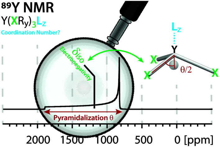
 The yttrium chemical shift signature of molecular and solid-state structures is determined by two key factors: electronegativity (isotropic chemical shift) and pyramidalization (anisotropy) of the anionic ligands.
Abstract
Yttrium is present in various forms in molecular compounds and solid-state structures; it typically provides specific mechanical and optical properties. Hence, yttrium containing compounds are used in a broad range of applications such as catalysis, lasers and optical devices. Obtaining descriptors that can provide access to a detailed structure–property relationship would therefore be a strong base for the rational design of such applications. Towards this goal, 89Y (100% abundant spin ½ nucleus), is associated with a broad range of NMR chemical shifts that greatly depend on the coordination environment of Y, rendering 89Y NMR an attractive method for the characterization of yttrium containing compounds. However, to date, it has been difficult to obtain a direct relationship between 89Y chemical shifts and its coordination environment. Here, we use computational chemistry to model the chemical shift of a broad range of Y(iii) molecular compounds with the goal to reveal the underlying factors that determine the 89Y chemical shift. We show through natural chemical shift (NCS)-analysis that isotropic chemical shifts can easily help to distinguish between different types of ligands solely based on the electronegativity of the central atom of the anionic ligands directly bound to Y(iii). NCS-analysis further demonstrates that the second most important parameter is the degree of pyramidalization of the three anionic ligands imposed by additional neutral ligands. While isotropic chemical shifts can be similar due to compensating effects, investigation of the chemical shift anisotropy (CSA) enables discriminating between the coordination environment of Y.
Introduction
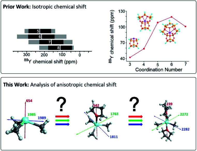
Yttrium-containing compounds and materials display unique physical and chemical properties and are thus found in a broad range of applications, including catalysis, high temperature oxide fuel cells, lasers (yttrium-aluminium garnet – YAG), radar technology, and superconductors. They are also used as additives to improve alloy strength and heat and shock resistance of lenses.1–4 Yttrium shows similar chemical properties as the lanthanides, and is also classified as a “rare-earth-element”. In its most common +III oxidation state, yttrium is diamagnetic and as yttrium has only a single stable isotope possessing a nuclear spin of ½ it is ideally suited for NMR. However, 89Y NMR suffers from low receptivity and long relaxation times of the yttrium nucleus, leading to rather long NMR experiments,5 unless hyperpolarization schemes such as dynamic nuclear polarization (DNP) are used.6–11 Furthermore, despite large chemical shift windows and its sensitivity to small changes in geometry and coordination, it is often difficult to rationalize chemical shift patterns (Fig. 1).
Fig. 1. Prior work focused on the analysis of isotropic chemical shifts to rationalize trends in 89Y chemical shifts.6,12,15,16 This work shows the analysis of the anisotropic chemical shifts yielding valuable insights in understanding trends in 89Y NMR.
In molecular inorganic chemistry, Schaverien published seminal work on 89Y chemical shifts.12 They found in particular across a series of compounds having fundamentally important ligands that the 89Y NMR resonance shifts to progressively higher field as σ-donating alkyl groups are sequentially substituted by groups of increased electronegativity and π-donating ability. A clear trend in decreasing electron donation to the yttrium center was found starting from C5Me5 > alkoxides > aryloxides > amides > alkyls. However, across a series of yttrium complexes differing by the coordination number, the presence of Lewis base adducts can result in both increased shielding and deshielding at the yttrium nucleus, making it difficult to have clear assignment.13,14
NMR spectral interpretation on oxides using 89Y NMR shows that the isotropic chemical shifts tend to decrease for increasing coordination numbers. However, due to other structural parameters the shift range of distinct coordination number overlaps too strongly to unambiguously assign a coordination number.16,17 Another example from our laboratory, exploiting DNP SENS data, has concentrated on assigning specific chemical shift signatures to specific Y(iii) surface sites, based on DFT calculated chemical shifts. 89Y chemical shift correlates with the coordination number, with higher coordination numbers leading to higher chemical shifts, a contrary trend to what was found for yttrium containing oxides.16 The difference of behaviour between trends found across bulk and surface sites remains unclear (Fig. 1).6
Overall, it appears that while chemical shift can give valuable information about the local structure around yttrium, a fundamental understanding on factors determining specific chemical shift signatures is needed. Recent advances in computational chemistry allow for the precise calculation of chemical shift tensors and its their analysis in terms of diamagnetic, paramagnetic and spin–orbit contributions. Furthermore, each chemical shift component can be further assigned to contribution of individual localized orbitals via natural localized molecular orbital (NLMO) analysis. This method has been applied to various nuclei (13C, 15N, 17O, 27Al, 77Se, 125Te, 195Pt etc.) to provide understanding of NMR parameters on a molecular level.18–27
Herein we show by DFT calculations using a series of distinct molecular Y(iii) complexes, the underlying factors for their chemical shift signature in dependence on the ligands and coordination number.
Chemical shift tensor
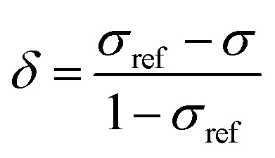
In order to obtain an in-depth understanding of the shielding tensors, knowledge of its relationship to molecular symmetry and molecular electronic structure is required.28 The calculated shielding value σ describes the degree of magnetic shielding at a nucleus in a molecule and is related to an experimentally observable chemical shift δ as follows:
 |
1 |
where σref is the shielding value associated with a nucleus for an arbitrarily chosen reference sample. In the case of 89Y NMR, YCl3 and Y(NO3)3 are most often used.29
NMR frequency shifts result from local magnetic fields that are induced around the nucleus and thus alter the net effect of the external magnetic field B0. Several factors contribute to the magnitude of these local fields: the gyromagnetic ratio (γ) of the nucleus, the electronic structure around the nucleus as well as the orientation of the molecule with respect to B0. Increasingly positive values of δ indicate magnetic deshielding, whereas increasing values of σ indicate magnetic shielding. The Hamiltonian commonly used to describe the shielding interaction is defined as:
| Ĥ = γ·B0·σ̈·Î | 2 |
where Î is the nuclear spin operator, and σ̈ is the shielding tensor (vectors are denoted in boldface, and tensors are denoted using an umlaut). The shielding tensor allows the description of the magnitude and the orientation dependence of the shielding interaction and is in 3D Cartesian space defined as:
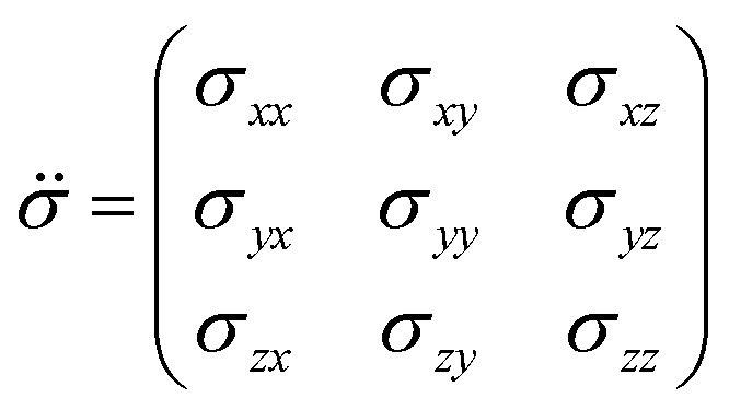 |
3 |
where each element σij represents the i-component of shielding when B0 is applied along the j-axis. The symmetric portion of the shielding tensor can be diagonalized into its own principal axis system (PAS):
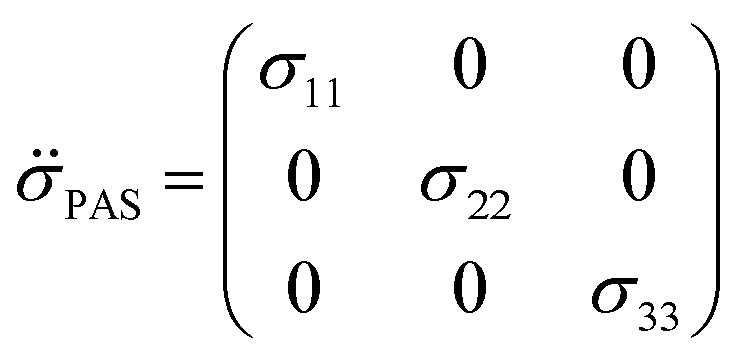 |
4 |
By convention, the principal components are assigned such that σ11 < σ22 < σ33. The isotropic shielding value σiso is defined as the average of the three principal components (eqn (5)). While only the isotropic chemical shift is observed in liquid state NMR, because of averaging through molecular tumbling, these values are accessible from solid-state NMR, either by using static conditions or low magic angle spinning.
 |
5 |
| δii = σrefiso – σii (i = 1, 2, 3) | 6 |
Generally speaking, the parameters of the chemical shift tensor are measured experimentally by NMR spectroscopy, whereas the shielding tensor parameters are obtained from computational approaches.
Diamagnetic and paramagnetic shielding
According to Ramsey's formulation, shielding contributions can be decomposed into diamagnetic σdia and paramagnetic σpara+SO terms, which also include contributions from spin–orbit coupling (eqn (7)).28,30,31 The diamagnetic term arises mostly from core electrons, where the applied magnetic field B0 induces circulation of electrons and therefore a small magnetic field opposing the applied magnetic field at the nucleus; this term leads to shielding and is mostly independent of the ligands bound to the observed nuclei. In contrast, the paramagnetic term originates from the mixing of the ground state with various excited states induced by B0 and mostly leads to deshielding. Both terms can be calculated using integration that describes the degree of superposition between the two corresponding wave functions.
| σ = (σdia + σpara+SO) | 7 |
 |
8 |
Deshielding of a nucleus is thus expected along the direction i, if an occupied orbital on this nucleus can be “superimposed” onto a vacant orbital on the same nucleus rotated by 90° along the axis i (see Fig. 2). Notably, the extent of deshielding increases with a decreasing energy gap between the two orbitals and paramagnetic shielding is therefore most strongly affected by frontier molecular orbitals (FMOs) – energetically high-lying occupied and low-lying vacant orbitals.
Fig. 2. Magnetically induced coupling of occupied and vacant orbitals leading to a deshielding along the i-axis.
Computational details
Geometry optimizations calculations were performed with the B3LYP32 functional in combination with the 6-31g(d)33 and lanl2dz34 basis sets – for main group elements and Y, respectively – using the Gaussian 09 (revision d1) program suite.35 Chemical shift calculations were performed with the ADF 2014 (ref. 36) code using the B3LYP functional including third-generation Grimme's dispersion corrections and Becke–Johnson damping (B3LYP-D3)37 in combination with a TZP38 basis set with the all-electron relativistic zeroth-order regular approximation (ZORA)39 in its spin–orbit two-component form. For the natural localized molecular orbitals (NLMO) analysis of the shielding principal components the NBO 6.0 (ref. 40) code is used as implemented in ADF 2014 with the revised Perdew–Burke–Ernzerhof (revPBE)41 functional and TZP basis set for large complexes (>25 atoms) or a combination of B3LYP-D3 and TZP for small complexes. The chemical shift of 89Y derived from the computed shielding is referenced to Y(OAr)3 (OAr = 2,6-di-tert-butyl-4-methylphenoxy, 167 ppm with respect to an aqueous solution of Y(NO3)3 taken as reference which forms the hydrated cation [Y(H2O)6–8]3+ (0 ppm) in water).6 Using experimentally measured compounds for benchmark calculations we could show that the methodology in use is able to accurately calculate the trends in shielding of organo-yttrium-complexes.
Results and discussion
Calibration
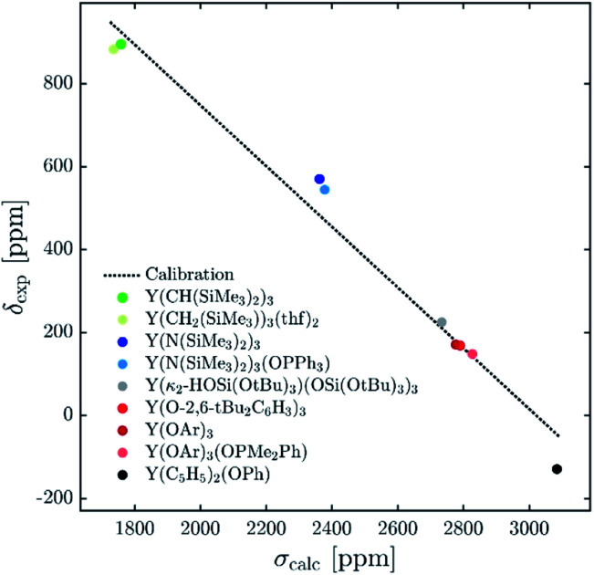
The 89Y chemical shifts of a series of yttrium molecular compounds, whose experimental values are known, are calculated on the revPBE and B3LYP level of theory.15 The series consists of yttrium complexes with varying ligands (alkyl, amido, alkoxy and C5H5 groups) and coordination number (3–7). The plot of experimental 89Y chemical shifts (δexp) vs. the calculated shieldings (σcalc) showed satisfying linearity correlation over the whole range, thus validating the computational method used (see Fig. 3). The slope and the intercept of the model are comparable to the parameters previously reported. Furthermore, the calculations were benchmarked by comparing the calculated individual principal components for two reported solid state 89Y NMR spectra of Y(OAr)3 and Y(κ2-HOSi(OtBu)3)(TBOS)3 (see Fig. S1,† TBOS = tris(tert-butoxy)siloxy).6
Fig. 3. Plot of experimental isotropic chemical shifts (δexp) versus calculated isotropic shieldings (σcalc) for geometry-optimized organometallic complexes (OAr = 2,6-di-tert-butyl-4-methylphenoxy). The linear least-squares fit obtained gave the following equation: δcalc = –0.727σcalc + 2114.1.
Isotropic shielding
The 89Y NMR resonance shifts to progressively higher field as σ-donating alkyl groups are sequentially substituted by groups of increased electronegativity and π-donating ability (C5Me5 > aryloxides > amides > alkyls). However, a clear correlation for yttrium complexes of differing coordination number could not be found. For example, Y(CH(SiMe3)2)3 and Y(CH2(SiMe3))3(thf)2, Y(N(SiMe3)2)3 and Y(N(SiMe3)2)3(OPPh3) as well as Y(OAr)3 and Y(OAr)3(OPMe2Ph) have virtually the same isotropic shielding (and chemical shift) (1759 vs. 1736 ppm, 2362 vs. 2379 ppm, 2777 vs. 2828 ppm).
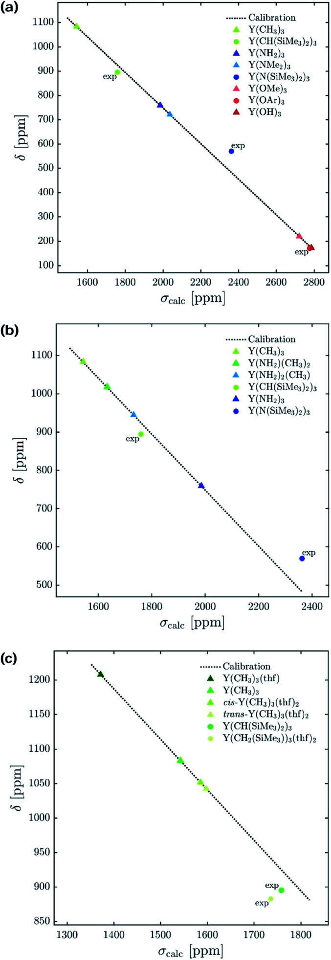
To understand the origin of these observations, we turned our focus on simple model systems in order to probe the effect of a broad range of structural parameters on chemical shift (ligands, coordination numbers and geometries). Four classes of coordinated yttrium molecular compounds are studied: alkyl, amido, alkoxy and chlorido yttrium complexes as well as mixed forms. For the homoleptic three-coordinated complexes, substituting the ligands from alkyl (–CH3) to amido (–NH2), chlorido (–Cl) and hydroxo (–OH) leads to more shielding, e.g. σiso = 1542 ppm for Y(CH3)3, σiso = 1986 ppm for Y(NH2)3, σiso = 2106 ppm for YCl3 and σiso = 2786 ppm for Y(OH)3 (see Fig. 4a). This is in line with what is expected from the Ramsey equations (eqn (8)) which predict that the extent of deshielding decreases with an increasing energy gap between the two frontier molecular orbitals (FMO) involved. In the series the electronegativity of the ligand central atom increases, leading to a higher energy difference between occupied and vacant orbitals (vide infra). To include the effect of larger ligands on the shielding, the hydroxy and amido groups in Y(OH)3 and Y(NH2)3 are replaced by methoxy and dimethylamido groups, respectively.
Fig. 4. Isotropic chemical shift (δ) versus calculated isotropic shielding (σcalc). For model complexes the chemical shift values were predicted using a calibration method based on B3LYP as functional. Experimentally obtained values15 are labelled with ‘exp’ (OAr = 2,6-di-tert-butyl-4-methylphenoxy). (a) Electronegativity and steric effects, (b) gradual substitution of alkyl ligands by amido ligands, and (c) effect of coordination geometry.
Interestingly, a similar isotropic shielding is observed in both cases (σiso = 1986 ppm for Y(NH2)3vs. σiso = 2037 ppm for Y(NMe2)3 and σiso = 2786 ppm for Y(OH)3vs. σiso = 2722 ppm for Y(OCH3)3). When alkyl, amido and alkoxy model complexes are directly compared with their real analogues one finds similar shielding values in case of the alkoxy complexes (σiso = 2786 ppm for Y(OH)3vs. σiso = 2777 ppm for Y(OAr)3), but a substantial offset for the alkyl and amido complexes (σiso = 1542 ppm for Y(CH3)3vs. σiso = 1759 ppm for Y(CH(SiMe3)2)3 and σiso = 1986 ppm for Y(NH2)3vs. σiso = 2362 ppm for Y(N(SiMe3)2)3). However, the general trend is predicted correctly. Analysis of the mixed alkyl amido complexes shows a gradual increase in shielding when the methyl ligands are substituted for amine ligands, e.g. σiso = 1542 ppm for Y(CH3)3, σiso = 1632 ppm for Y(CH3)2(NH2), σiso = 1732 ppm for Y(CH3)(NH2)2 and σiso = 1986 ppm for Y(NH2)3 (see Fig. 4b). Again, this is in line with what is expected from the Ramsey equations. In order to evaluate the influence of the coordination geometry, structures with one or two thf-ligands coordinated to Y(CH3)3 are evaluated, as well as a hypothetical flat Y(CH3)3. In the case of the five coordinated Y(CH3)3(thf)2 both, the cis and the trans-isomer are studied. Interestingly, the isotropic shielding for the hypothetical flat Y(CH3)3 is around 400 ppm lower than for its pyramidalized ground state structure (σiso = 1135 ppm for flat Y(CH3)3 and σiso = 1542 ppm for Y(CH3)3). The isotropic shielding is calculated to be almost equal for three and five coordinated complexes, whereas the shielding is around 200 ppm lower for the four coordinated Y(CH3)3(thf) (σiso = 1542 ppm for Y(CH3)3, σiso = 1372 ppm for Y(CH3)3(thf), σiso = 1586 ppm for cis-Y(CH3)3(thf)2 and σiso = 1598 ppm for trans-Y(CH3)3(thf)2) (see Fig. 4c). This was also observed experimentally for three and five coordinated complexes,15 while no data exist for the corresponding four coordinated complex. As the isotropic shielding does not allow to distinguish complexes with similar ligands but different coordination geometry, we next analysed the principal components of the shielding tensor.
Anisotropic shielding tensors
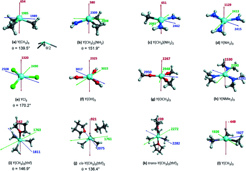
The shielding tensor was found to be axially symmetric (σ22 = σ33) for the homoleptic three coordinated organoyttrium complexes as expected from their C3v/D3h-symmetry. For homo- as well as heteroleptic three coordinated complexes, the computed shielding tensors are oriented in the same way. The tensor is oriented such that σ22 and σ33 are parallel to the plane going through the three ligand central atoms, while σ11 is perpendicular to it (see Fig. 5a–h). The shielding tensors for the structures with one or two thf-ligands coordinated to Y(CH3)3 are more or less axially symmetric with the exception of cis-Y(CH3)3(thf)2, where a principal axis falls in between the two thf ligands. The orientations of the principal components are shown in Fig. 5i–k and have a similar orientation throughout the series. σ22 and σ33 are again parallel to the plane spanned by the three carbon central atoms. This leads in turn to the alignment of σ11 with the yttrium oxygen bonds for Y(CH3)3(thf) and trans-Y(CH3)3(thf)2 but not for cis-Y(CH3)3(thf)2, where σ11 is directed in between the two thf ligands. Substituting the ligands from alkyl (–CH3) to amido (–NH2), chlorido (–Cl) and hydroxo (–OH) leads to more shielded principal components, e.g. σ11 = 654 ppm for Y(CH3)3, σ11 = 1129 ppm for Y(NH2)3, σ11 = 1320 ppm for YCl3 and σ11 = 2325 ppm for Y(OH)3. Interestingly, there was almost no change in the magnitude of the principal components when replacing the hydroxo groups by methoxy groups, whereas one can observe two rather large changes when the NH2-groups are replaced by N(Me)2-groups (σ11 = 1129 ppm and σ22 = 2413 for Y(NH2)3vs. σ11 = 1530 ppm and σ22 = 2290 for Y(NMe2)3). Hence, a similar isotropic shielding is observed due to compensating effects. The difference between Y(OH)3 and Y(OMe)3 is very small and the values are therefore considered to be equal within numerical precision. For the mixed alkyl amido complexes we noticed that within the series (Fig. 5a–d) two out of the three principal components have approximately the same magnitude (for example σ11 = 654 ppm, σ22 = 1985 ppm for Y(CH3)3 and σ11 = 580 ppm, σ22 = 2008 ppm for Y(CH3)2(NH2)) and only one principal component changes substantially (σ33 = 1989 ppm for Y(CH3)3 and σ33 = 2309 ppm for Y(CH3)2(NH2)). In the case of three- and five-coordinated yttrium, it is evident that the magnitude of the principal components is again explained by two compensating effects. For instance, σ11 is around 400 ppm higher for Y(CH3)3 than for trans-Y(CH3)3(thf)2, while the values of σ22 and σ33 are around 250 ppm lower. When Y(CH3)3 and flat Y(CH3)3 are compared one finds a large difference in σ11, but σ22 and σ33 are almost identical (σ11 = –449 ppm for flat Y(CH3)3 and σ11 = 654 ppm for Y(CH3)3, σ22 ≈ σ33 ≈ 1950 ppm).
Fig. 5. Three-coordinated yttrium model complexes used to study σ and π-effects of the ligands (a–h) and yttrium model complexes used to further study the influence of the coordination number (i–l). For complexes with non-planar geometry of the three anionic ligands, the pyramidalization θ is given below the complex name. The depicted values represent the shielding along the three principal components of the respective shielding tensor. Colour code: σ11 = red, σ22 = green and σ33 = blue.
While the analysis of the principal components of the shielding tensor reveals that compensating effects explain previous difficulties in interpreting isotropic chemical shift values, they do not explain the origin of this effect. Recent studies by our group have shown that natural chemical shift (NCS) analysis is a valuable method to understand individual shielding contributions and that detailed knowledge of the structure and geometry of the complex in study is key for the interpretation of the obtained values.
NCS analysis
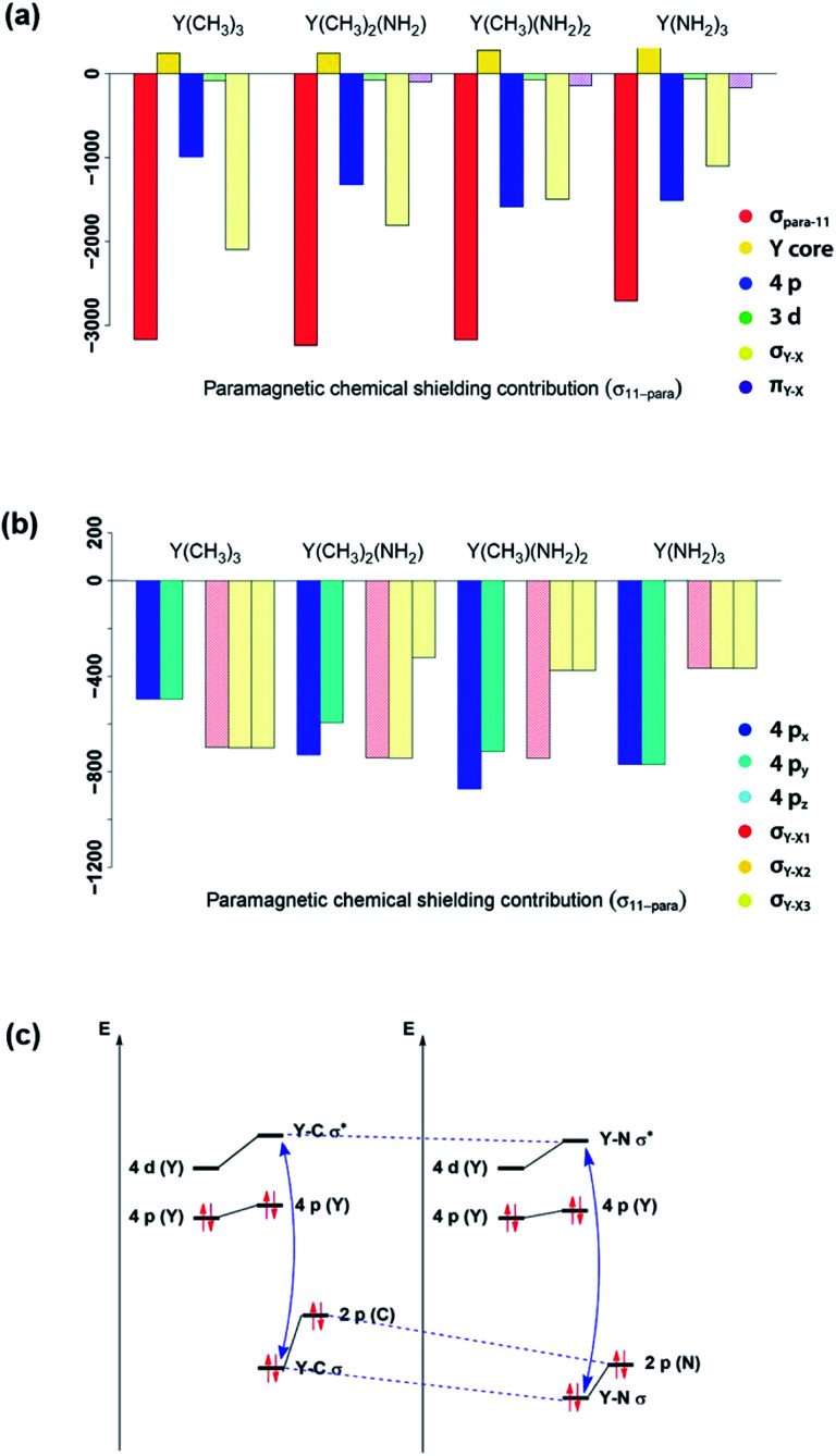
In order to understand the origin of the observed compensating effects, the shielding tensor and its various contributions (diamagnetic, paramagnetic & spin–orbit) are further analysed (see Fig. S3–S17†). Overall, the diamagnetic contributions are almost equal for all complexes, and no substantial spin–orbit contributions are found across this series. Thus, changes in chemical shift are mostly due to the paramagnetic term (σpara). NCS analysis allows evaluating the contributions of the specific natural localized molecular orbitals (NLMO) to σpara,42,43 and confirms that the diamagnetic yttrium shielding is primarily dominated from LMOs with high yttrium atomic orbital (AO) character. For the paramagnetic shielding contribution, small positive contributions of the core orbitals are also found, likely due to the arbitrary decomposition of the paramagnetic and diamagnetic terms (see Fig. 6a).
Fig. 6. Substitution effects: orbital contributions to σ11-para (a), detailed analysis of 4px, 4py, 4pz, σY–X1, σY–X2 and σY–X3 contributions to σ11-para (b) and effect of substituting an alkyl ligand by an amido ligand (c). ΔEN between σ- and σ*-orbitals increases upon substitution.
Looking first at alkyl vs. amido ligands, contributions of yttrium d-orbitals and nitrogen p-orbitals that are attributed to the π-bonds did not seem to be important in any of the complexes. Differences in the paramagnetic shielding tensor are thus largely explained by changes in the contribution of the yttrium 4p orbitals and the σ-bonding orbitals with the ligands (see Fig. 6a). An in-depth analysis of the yttrium 4px, 4py, 4pz and yttrium–ligand σ-bond contributions (σY–X1, σY–X2 and σY–X3, where X1, X2 and X3 denotes the respective ligands) shows that replacing alkyl ligands by amido ligands leads to a drop in the contribution of the corresponding σY–X-orbital (see Fig. 6b). This is in line with the fact that the carbon central ligand atom of the ligand is less electronegative than nitrogen and its FMOs thus found to be higher in energy, leading to a smaller energy gap between occupied and vacant orbitals and thereby higher deshielding because these are close in energy (see Fig. 6c).
Note that beside the energy difference, the overlap between occupied and vacant orbitals is also important (eqn (8)). In our series, Y(NH2)3 is essentially planar and pyramidalization increases when substituting amido ligands with alkyl ligands (see Fig. 5a–d). The pyramidalization θ (average of twice the subtended angle at the yttrium atom given by one ligand central atom and the centroid of the three ligand central atoms, see Fig. 5a) increases in the order of Y(CH3)3 (139.5°) < Y(CH3)2(NH2) (151.9°) < Y(CH3)(NH2)2 (180°, planar geometry) = Y(NH2)3 (planar geometry). This can be attributed to the smaller σ-donation of N as well as the additional π-donating ability of the amido ligands that both favour planar geometry, allowing for a better overlap between the lone pair on nitrogen and the empty dxz- and dyz-orbitals. Upon reducing the degree of pyramidalization, one expects that the overlap between the 4px,4py and σY*–X orbitals is increased, hence leading to a higher contribution, which is indeed observed. Next, the effect of each principal component (σ11, σ22 and σ33) related to the corresponding angular momentum operator (L[combining circumflex]z, L[combining circumflex]y and L[combining circumflex]x) is analysed. The effect of the angular momentum operator and hence deshielding is the largest, if there is a 90° relationship between the angular momentum operator and corresponding orbitals with p-like symmetry.28 The angular momentum operator L[combining circumflex]z in the case of Y(CH3)3 is perpendicular to the plane spanned by the three ligands and thus there is the same contribution for each 4p and σ-bonding orbital (see Fig. 7).
Fig. 7. Location of the angular momentum operators for Y(CH3)3 (σ11 ↔ L[combining circumflex]z, σ22 ↔ L[combining circumflex]y and σ33 ↔ L[combining circumflex]x).
However, the situation changes for L[combining circumflex]y. σY–Me1 has a perfect 90° angle, whereas σY–Me2 and σY–Me3 are placed in a 30° angle with respect to the direction of L[combining circumflex]y. As expected, one large and two rather small contributions (see Fig. S8†) can be observed. As σY–Me1 is placed along the x-axis, the contribution drops to zero when L[combining circumflex]x is applied. σY–Me2 and σY–Me3 are found to have a 60° angle with respect to L[combining circumflex]x, which leads in turn to an equal but higher contribution compared to the values calculated for σ22 (see Fig. S8†). The individual contributions of σ22 and σ33 for Y(CH3)2(NH2) and Y(CH3)(NH2)2 can also be understood by means of the orbital rotation model presented above (see ESI†). Overall, NCS analysis of σ22 and σ33 within this series yields the same result: the magnitude of the contribution of the yttrium–ligand-σ-bonds decreases and the contribution of the yttrium 4p increases upon gradual substitution of the alkyl ligands by amido ligands.
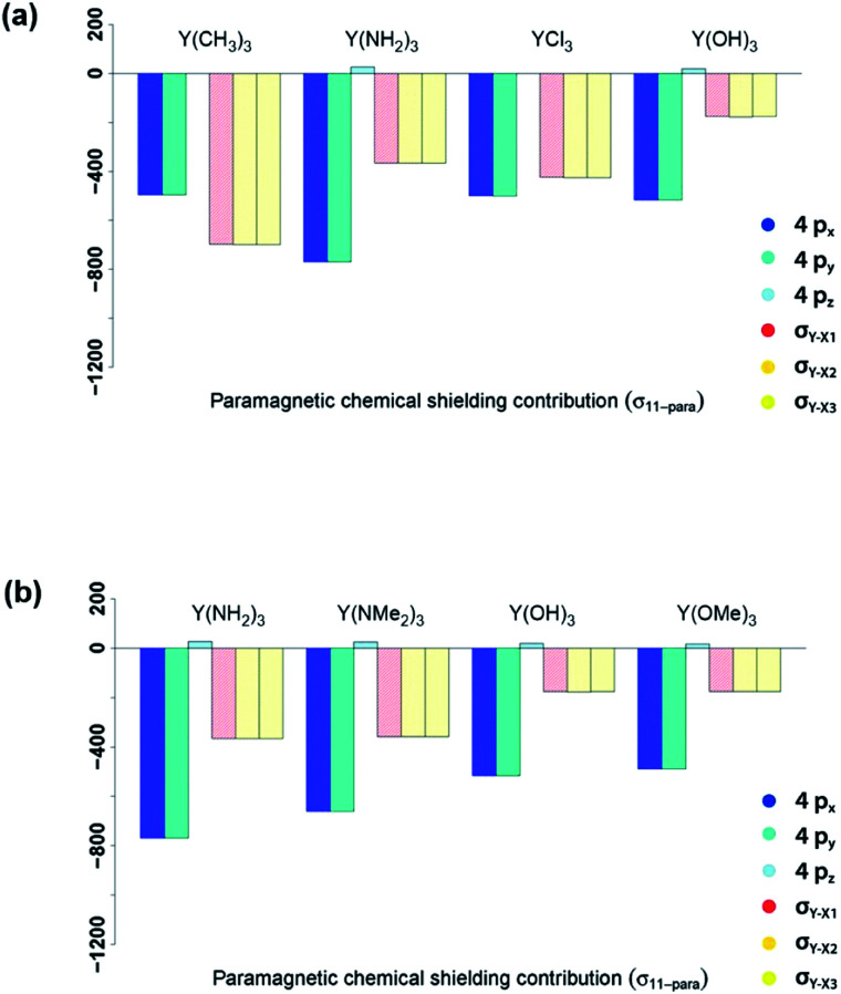
In summary, NCS analysis of the alkyl and amido model complexes shows that yttrium 4p and yttrium–ligand σ-bonds determine the chemical shift and that trends concerning these orbitals can be explained by differences in electronegativity and extent of pyramidalization. More specifically, a more electronegative ligand central atom leads to a diminished contribution of the respective σ-bond and less pyramidalization leads to an increased contribution of the respective yttrium 4p because of better orbital overlap. To validate this hypothesis, we next investigated YCl3 and Y(OH)3. In terms of the electronegativity of the ligand central atom, amido and chlorido ligands are comparable, whereas the electronegativity of oxygen is significantly higher. As expected, similar σ-bond contributions for the chlorido and the amido-complexes are observed, as well as the diminished contributions of the σY–O-bonds for Y(OH)3 (see Fig. 8a).
Fig. 8. Electronegativity and steric effects: 4px, 4py, 4pz, σY–X1, σY–X2 and σY–X3 contributions to σ11-para comparing π-donor effects (a) and the effect of larger ligands (b).
As Y(NH2)3, YCl3 and Y(OH)3 are all almost planar, one would expect similar contributions of the yttrium 4p orbitals. The calculated contributions of the 4p orbitals are equal for YCl3 and Y(OH)3, but significantly lower (less negative) when compared to Y(NH2)3. As the 4p orbitals interact with the dxy and dx2–y2-orbitals and those in turn with the additional lone pair from the ligand (consistent with the 180°-angle of Y–O–H) the orbitals involved in the 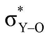 -bonds are raised in energy. The larger difference in energy accounts for the smaller contributions in the case of YCl3 and Y(OH)3 compared to Y(NH2)3.
The analysis of the shielding tensor of Y(OH)3 and Y(OMe)3 revealed that their principal components are equal within numerical precision, whereas the principal components of Y(NH2)3 and Y(NMe2)3 differed significantly. More specifically, in case of the dimethylamido complex σ11 is less deshielded and σ22/σ33 are more deshielded. The contribution of the σY–N-bonds are the same in both complexes as expected from the Ramsey equations (eqn (8)). The differences in σ11 and σ22/σ33 between Y(NH2)3 and Y(NMe2)3 originate from structural differences between the two complexes. Both Y(NH2)3 and Y(NMe2)3 show trigonal planar geometry at the metal center, however, the methyl groups are no longer on the same plane as the 3 Y–N bonds and are rotated due to steric repulsion between the methyl groups. This will in turn lead to a decreased π-backdonation of the ligand. Thus, the rotation gives rise to an additional interaction between the nitrogen p-orbital and the σ*-orbitals (in plane) therefore leading to a higher energy difference between the yttrium 4p orbitals and the σ*-orbitals (in plane) and thus resulting in a lower contribution for σ11 and a higher contribution for σ22/σ33.
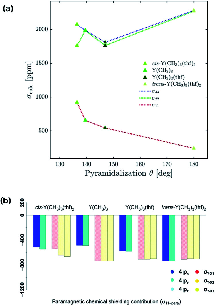
Y(NH2)3, YCl3 and Y(OH)3 are all planar and do not offer to assess the effect of pyramidalization. However, the degree of pyramidalization determines the possible overlap and therefore the magnitude of the contribution of the yttrium 4p orbitals. In order to evaluate directly the effect of the pyramidalization θ, structures with one or two thf-ligands coordinated to Y(CH3)3 are evaluated, as well as a hypothetical flat Y(CH3)3. Structures with one or two thf-ligands coordinated to Y(CH3)3 show that the pyramidalization θ increases in the order of cis-Y(CH3)3(thf)2 (136.4°) < Y(CH3)3 (139.5°) < Y(CH3)3(thf) (146.9°) < trans-Y(CH3)3(thf)2 (planar geometry).
For σ11 a clear relationship with the pyramidalization θ was observed (Fig. 9a): the more planar structures yield lower values (σ11 = 921 ppm for cis-Y(CH3)3(thf)2, σ11 = 654 ppm for Y(CH3)3, σ11 = 542 ppm for Y(CH3)3(thf), σ11 = 239 ppm for trans-Y(CH3)3(thf)2 and σ11 = –449 ppm for flat Y(CH3)3). The NCS-analysis revealed that the observed trend with the pyramidalization θ in σ11 for Y(CH3)3, Y(CH3)3(thf) and trans-Y(CH3)3(thf)2 is solely due to the increasing contribution of the yttrium 4p orbitals, whereas all the other contributions are staying constant. This is exemplified by the comparison of Y(CH3)3 and flat Y(CH3)3, where the only difference is the pyramidalization. The overall compensating effect of σ22 and σ33 is due to a gradual decrease of the σ-bond contributions. Contributions from the axial yttrium oxygen σ-bonds are very small and can be neglected (see Fig. S14†). The trend can be understood by considering the consequences of the π-bonding from the thf ligand(s). The two axially placed thf-ligands in trans-Y(CH3)3(thf)2 lead to a substantial rise of the corresponding dxz and dyz orbitals, thus increasing the energy difference between σ and σ*-orbitals and leading to diminished contributions. This effect is less pronounced when only one thf ligand is placed axially (Y(CH3)3(thf)) and not at all for Y(CH3)3. Consequently, σ22 and σ33 are almost equal for Y(CH3)3 and flat Y(CH3)3. In the case of σ22 and σ33 for cis-Y(CH3)3(thf)2 the yttrium carbon σ-bond contribution is only moderately pronounced since the bond between yttrium and thf in cis-Y(CH3)3(thf)2 is elongated. Additionally, as the bond length is different for the two thf ligands, σ22 and σ33 are not similar.
Fig. 9. Effect of the pyramidalization θ: (a) 4px, 4py, 4pz, σY–X1, σY–X2 and σY–X3 contributions to σ11-para. (b) Correlation of the simulated optimal pyramidalization θ with the principle axis of the shielding tensors.
Overall, NCS-analysis of the chosen model complexes (Y(NH2)3, Y(NMe2)3, YCl3, Y(OH)3 and Y(OMe)3 as well as differentially coordinated Y(CH3)3) confirmed the established model from the alkyl amido series. Yttrium 4p orbitals and yttrium–ligand σ-bonds determine the chemical shift and trends concerning these orbitals can be explained by differences in electronegativity and pyramidalization. Less electronegative ligand central atoms have FMOs that are higher in energy, hence leading to a smaller energy gap between occupied and vacant orbitals and deshielding increases if these are close in energy. Less pyramidalization leads to an increased contribution because of better orbital overlap between yttrium 4p orbitals and antibonding yttrium–ligand σ*-orbitals.
Application of the model on large complexes
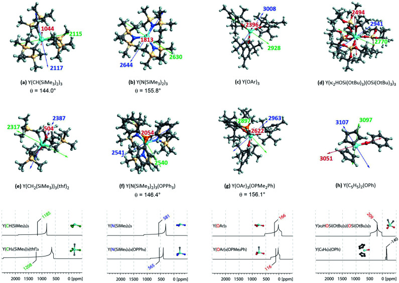
Complexes selected from the literature were chosen such that they fulfil two conditions: on the one hand they should have the same ligand central atom bound to Y as our model systems (C, N, O), on the other hand they should be present in different coordination numbers (3, 4, 5). Y(κ2HOSi(OtBu)3)(OSi(OtBu)3)3 is studied to include complexes with a κ2-bond and Y(C5H5)2(OPh) is selected as one of the most shielded nucleus and the signal therefore found very far upfield. We showed via NCS analysis of the model complexes that knowledge of the geometry is key for the interpretation of shielding. Structurally Y(CH(SiMe3)2)3 resembles Y(CH3)3 (pseudo-C3v-symmetry), their respective pyramidalization is similar (θmodel = 139.5° vs. θreal = 144.0°). Y(CH2(SiMe3))3(thf)2 has a tbp-structure (pseudo-D3h-symmetry), the methyl ligands are calculated to be in the same plane. For amido ligand, while Y(NH2)3 is completely planar, Y(N(SiMe3)2)3 is pyramidalized (θ = 155.8°). By adding one axial phosphine oxide ligand (Y(N(SiMe3)2)3(OPPh3)), pyramidalization is slightly increased (θ = 146.4°). The analysis of the bond lengths show that they are almost equal for model systems and real complexes (Y(CH3)3: 2.35 Å, Y(CH(SiMe3)2)3: 2.38 Å and Y(NH2)3: 2.17 Å, Y(N(SiMe3)2)3: 2.24 Å). In both cases one can see a slight increase of bond length when adding axial ligands (Y(CH2(SiMe3))3(thf)2: 2.43 Å and Y(N(SiMe3)2)3(OPPh3): 2.29 Å). Axial yttrium oxygen and yttrium carbon/nitrogen bonds have approximately the same lengths in the respective complexes (e.g. Y–N = 2.29 Å for Y(N(SiMe3)2)3(OPPh3) and Y–O = 2.32 Å).
Subsequently, the shielding tensors and orientations for the organometallic complexes are computed (Fig. 10). For all three-coordinated complexes the principal components of the shielding tensor are oriented such that σ22 and σ33 are parallel to the plane going through the three anionic ligand central atoms. No change is observed when studying four and five coordinated derivatives. For Y(κ2HOSi(OtBu)3)(OSi(OtBu)3)3σ22 and σ33 are found to be parallel to the plane derived from the central atoms of the three –OSi(OtBu)3 anionic ligands and σ11 is therefore placed in between the two yttrium–oxygen bonds of the HOSi(OtBu)3 κ2-neutral ligand. Y(C5H5)2(OPh) is almost isotropic, the principal components are oriented such that σ11 is aligned with the yttrium–oxygen bond.
Fig. 10. Top: NMR shielding tensor orientations of selected yttrium complexes (OAr = 2,6-di-tert-butyl-4-methylphenoxy). For complexes with non-planar geometry of the three anionic ligands, the pyramidalization θ is given below the complex name. The depicted values represent the shielding along the three principal components of the respective shielding tensor. Colour code: σ11 = red, σ22 = green and σ33 = blue. Bottom: DFT calculated solid state 89Y NMR of various organo-yttrium-complexes reported in literature.15 The isotropic chemical shifts are depicted in green, blue and red for carbon, nitrogen and oxygen based ligands, respectively.
Investigation of the isotropic shielding showed that adding axial oxygen-based ligands to three coordinated complexes has almost no influence. This observation is in line with the experimental data obtained by White et al.15 The performed calculations suggest that this is due to compensating effects of the principal components. For instance, σ11 is found to be 500 ppm lower in Y(CH2(SiMe3))3(thf)2 than in Y(CH(SiMe3)2)3, while σ22 and σ33 are both 250 ppm higher. For nitrogen and oxygen-based complexes the compensating effects are found to be reversed: For Y(N(SiMe3)2)3(OPPh3) σ11 is 200 ppm higher than in Y(N(SiMe3)2)3, while σ22 and σ33 are both lowered by around 100 ppm. Similarly, for Y(OAr)3(OPMe2Ph) σ11 is 200 ppm higher than in Y(OAr)3, while σ22 and σ33 are both lowered by around 50 ppm. The study of Y(iii) model complexes allowed us to provide a relationship between the degree of pyramidalization and the magnitude of the contribution from the yttrium 4px,y orbitals. The lower the degree of pyramidalization (the more planar), the more deshielded is σ11 and the larger the anisotropy becomes. Due to steric and electronic reasons Y(N(SiMe3)2)3 is no longer planar, leading to a much lower contribution of the yttrium 4p orbitals when compared to the situation in Y(NH2)3. As described above, the pyramidalization is further enhanced by adding one axial phosphine oxide ligand (Y(N(SiMe3)2)3(OPPh3)), thus leading to an additional decrease of the contribution of the yttrium 4p orbitals. The same is true for Y(OAr)3 and Y(OAr)3(OPMe2Ph), respectively. The reversed trend for Y(CH2(SiMe3))3(thf)2/Y(CH(SiMe3)2)3 has in fact the same origin. By adding two axial thf ligands, the carbon-based ligands are forced to adopt a planar geometry which in turn leads to huge increase of the contribution of the yttrium 4p orbitals. A detailed list of all individual contributions to the shielding is given in the ESI (see Table S1–S60†).
In summary, the established model can easily be extended to large complexes. As shown above, the consequences of the pyramidalization and the differences in electronegativity manifest themselves in the principal components of the shielding tensor and account therefore for the observed trends, including compensating effects. In general, the lower the difference of electronegativity between Y and this atom, the more deshielded (the higher) is the chemical shift and the lower the degree of pyramidalization (the more planar), the more anisotropic is the chemical shift. Organo-yttrium complexes with differing coordination number can thus easily be distinguished by obtaining their solid state 89Y NMR spectra (see Fig. 10). For example, Y(CH(SiMe3)2)3 and Y(CH2(SiMe3))3(thf)2 have almost the same isotropic shift, but as the shielding tensor of Y(CH2(SiMe3))3(thf)2 is much more anisotropic, both complexes can easily be distinguished. Note, that both complexes are axially symmetric, which can also be derived from the line shape of their powder pattern.
CSA analysis of surface and bulk oxide models
Silica-supported Y(iii) sites and the corresponding bulk yttrium silicates were modelled using a cluster approach, with yttrium bound via oxygen ligands in a siloxane cage (Fig. 11a–f).6
Fig. 11. Left: Silica-supported Y(iii) sites (a–c) and bulk yttrium oxide models (d–f). The depicted values represent the shielding along the three principal components of the respective shielding tensor. Colour code: σ11 = red, σ22 = green and σ33 = blue. Right: DFT calculated solid state 89Y NMR (g) of silica-supported Y(iii) sites (top) and bulk yttrium oxide models (bottom).15 The isotropic chemical shifts are depicted in red.
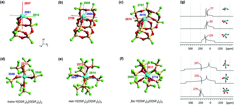
With surface species, different coordination environments associated with the amorphous silica surface were introduced with additional 10- or 12-membered rings to provide one or two additional siloxane bridge interactions with the yttrium ion, respectively. Unambiguous assignment of the yttrium environment based solely on its isotropic shielding is difficult as there is only a small (monotonous) shift across 3 to 5 coordinate species (3 coordinated yttrium: σiso = 2867 ppm, 4 coordinated yttrium: σiso = 2851 ppm and 5 coordinated yttrium: σiso = 2816 ppm). However, there are notable differences in the chemical shift anisotropy. While σ22 and σ33 are very similar, σ11 drops from 2807 ppm (3 coordinated yttrium) to 2674 ppm (5 coordinated yttrium), leading to a much larger span of the shielding tensor. Introduction of one or two siloxane bridges does not change the shielding along Z or Y direction, but along the X direction (see Fig. 11). Therefore, the most deshielded principal component (σ11) is placed along the X axis for 4 and 5 coordinated yttrium clusters. When compared with Y(OH)3 or Y(OAr)3 (σ11 = 2325 ppm for Y(OH)3 and σ11 = 2396 ppm for Y(OAr)3), σ11 is computed to be around 400 ppm lower than for the 3 coordinated yttrium cluster, which can be explained through the pyramidalization that is enforced through the rigid siloxane cage. In fact, σ11 of Y(OAr)3(OPMe2Ph) (2622 ppm) resembles the 3 coordinated yttrium cluster more as pyramidalization is enhanced through the addition of the phosphine oxide ligand.
In contrast, 89Y NMR shows that the isotropic chemical shifts for bulk silicates tend to decrease (increased shielding) for increasing coordination numbers,16 a contrary trend to what was found for the surface species (decreased shielding, vide supra).6 To this end, we investigated five and six coordinated yttrium silicate models (Fig. 11d–f). We found that additional siloxane ligands, modelled as the hexafluorosiloxane (F3Si–O–SiF3), to generate penta- or hexacoordinated species, can lead to shielding or deshielding depending on the specific situation. For instance, going from the pentacoordinated trans-Y(OSiF3)3(O(SiF3)2)2 (σiso = 2703 ppm) to hexacoordinated complexes can lead to shielding (σiso = 2709 ppm for mer-Y(OSiF3)3(O(SiF3)2)3) or deshielding (σiso = 2665 ppm for fac-Y(OSiF3)3(O(SiF3)2)3), depending on whether the three anionic ligands are in one plane or occupy one face of the octahedron. Overall, the values are very similar, which renders the assignment of the coordination number based on isotropic shielding rather challenging. However, the three complexes can easily be distinguished by their chemical shift anisotropy. For trans-Y(OSiF3)3(O(SiF3)2)2 one finds similar values as for mer-Y(OSiF3)3(O(SiF3)2)3 (σ11 = 2213 ppm, σ22 = 2848 ppm and σ33 = 3048 ppm for trans-Y(OSiF3)3(O(SiF3)2)2vs. σ11 = 2272 ppm, σ22 = 2814 ppm and σ33 = 3041 ppm for mer-Y(OSiF3)3(O(SiF3)2). In both cases the three anionic ligands are calculated to be in one plane. If the three ligands are pyramidalized – as for fac-Y(OSiF3)3(O(SiF3)2)3) – one would expect a substantially increased shielding along the z direction, which is indeed the case (σ11 = 2617 ppm).
In summary, we established that it is not the number of neutral ligands (in addition to the three charged ones) that defines the 89Y chemical shift, but the local geometry and the specific location of the three anionic ligands. This explains the difficulty to rationalize chemical shift on the basis of coordination geometry. Furthermore, it rationalizes the large spread of chemical shifts observed for Y having the same coordination number in bulk oxide materials. For a given coordination number, small differences in the position of oxygen atoms with respect to Y (due to defects and dislocation of anions) can lead to a significant difference in the localization of the negative charge on oxygen atoms in bulk materials (a parallel with the position of anionic ligands in molecular complexes or silicates), hence the large spread of chemical shift. While assignment of yttrium sites can therefore be challenging purely based on their isotropic chemical shift, the position of the anionic ligands (more negatively charged oxygens) leads to a specific chemical shift anisotropy signature that can be readily recorded by solid-state NMR.
Conclusions
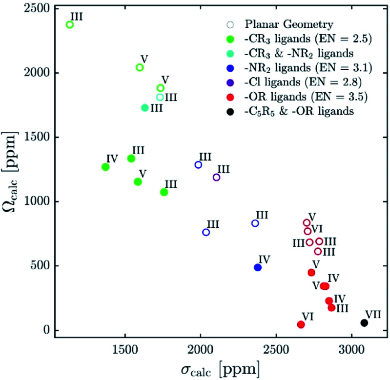
Recent reports explaining yttrium chemical shifts emphasized the importance of the σ- and π-donating ability of the ligands in order to obtain strong shielding. However, direct relationships between the chemical shift and the coordination number cannot be generally established and contrary trends can even be found. We could show through NCS analysis that isotropic chemical shifts can easily help to distinguish between different types of ligands solely based on the electronegativity of the atom of the anionic ligands directly bound to Y(iii) because it affects the energy gap between the key frontier molecular orbitals of these ligands that contribute to the chemical shift (see Fig. 12). In general, the lower the difference of electronegativity between Y and this atom, the more deshielded (the higher) is the chemical shift. Furthermore, NCS analysis demonstrates that the second most important parameter, that directs the chemical shift is not so much coordination number (as one may have expected), but the degree of pyramidalization (of the three anionic ligands). The lower the degree of pyramidalization (the more planar), the more deshielded is the chemical shift. In rare cases additional modulation through π-bonding orbitals is observed, more specifically if the energy of the σ*-orbital is raised through this interaction.
Fig. 12. Plot of calculated isotropic shieldings (σcalc) versus calculated span (Ωcalc) for geometry-optimized organometallic complexes.
While using isotropic chemical shifts alone makes the assignment of closely related yttrium compounds challenging, explaining previously reported difficulties in this field, we show that the shielding anisotropy, which is readily accessible by recording solid-state NMR, is much more sensitive and allows discriminating between sites (see Fig. 12). In general, if the three anionic ligands adopt a planar geometry, large anisotropy is observed. π-Bonding ligands favour planar geometries; however, an additional axial ligand can enforce pyramidalization and hence reduces the anisotropy of the complex. Shielding anisotropy is thus a discriminating factor and a molecular signature that can help to classify complexes within each class of compounds. We therefore think that solid-state 89Y NMR can thus be a powerful tool to distinguish between Y-containing compounds and materials, especially with recent advances in pulse sequences to extract anisotropy parameters as well as DNP SENS.11,44–47
Conflicts of interest
There are no conflicts to declare.
Supplementary Material
Acknowledgments
L. Lätsch is a recipient of the Oskar-Jeger-Scholarship. C. P. Gordon (ETH Zürich) is acknowledged for helpful discussions.
Footnotes
†Electronic supplementary information (ESI) available. See DOI: 10.1039/d0sc02321c
References
- O'Keefe B. J., Hillmyer M. A., Tolman W. B. J. Chem. Soc., Dalton Trans. 2001:2215–2224. [Google Scholar]
- Arndt S., Spaniol T. P., Okuda J. Angew. Chem., Int. Ed. 2003;42:5075–5079. doi: 10.1002/anie.200352532. [DOI] [PubMed] [Google Scholar]
- Edelmann F. T., Freckmann D. M. M., Schumann H. Chem. Rev. 2002;102:1851–1896. doi: 10.1021/cr010315c. [DOI] [PubMed] [Google Scholar]
- Emslie D. J. H., Piers W. Coord. Chem. Rev. 2002;233–234:131–155. [Google Scholar]
- Wu J., Boyle T., Shreeve J., Ziller J. Inorganic. 1993:1130–1134. [Google Scholar]
- Delley M. F., Lapadula G., Núñez-Zarur F., Comas-Vives A., Kalendra V., Jeschke G., Baabe D., Walter M. D., Rossini A. J., Lesage A., Emsley L., Maury O., Copéret C. J. Am. Chem. Soc. 2017;139:8855–8867. doi: 10.1021/jacs.7b02179. [DOI] [PubMed] [Google Scholar]
- Rossini A. J., Zagdoun A., Lelli M., Lesage A., Copéret C., Emsley L. Acc. Chem. Res. 2013;46:1942–1951. doi: 10.1021/ar300322x. [DOI] [PubMed] [Google Scholar]
- Caillot M., Copéret C., Emsley L., Chaumonnot A., Chizallet C., Raybaud P., Valla M., Digne M., van Bokhoven J. A., Lesage A., Rossini A. J. J. Am. Chem. Soc. 2015;137:10710–10719. doi: 10.1021/jacs.5b06134. [DOI] [PMC free article] [PubMed] [Google Scholar]
- Lumata L., Jindal A. K., Merritt M. E., Malloy C. R., Sherry A. D., Kovacs Z. J. Am. Chem. Soc. 2011;133:8673–8680. doi: 10.1021/ja201880y. [DOI] [PMC free article] [PubMed] [Google Scholar]
- Xing Y., Jindal A. K., Regueiro-Figueroa M., Le Fur M., Kervarec N., Zhao P., Kovacs Z., Valencia L., Pérez-Lourido P., Tripier R., Esteban-Gómez D., Platas-Iglesias C., Sherry A. D. Chem.–Eur. J. 2016;22:16657–16667. doi: 10.1002/chem.201602901. [DOI] [PMC free article] [PubMed] [Google Scholar]
- Blanc F., Sperrin L., Lee D., Dervişoglu R., Yamazaki Y., Haile S. M., De Paëpe G., Grey C. P. J. Phys. Chem. Lett. 2014;5:2431–2436. doi: 10.1021/jz5007669. [DOI] [PubMed] [Google Scholar]
- Schaverien C. J. J. Mol. Catal. 1994;90:177–183. [Google Scholar]
- Coan P. S., Hubert-Pfalzgraf L. G., Caulton K. G. Inorg. Chem. 1992;31:1262–1267. [Google Scholar]
- Bradley D. C., Chudzynska H., Hursthouse M. B., Motevalli M. Polyhedron. 1991;10:1049–1059. [Google Scholar]
- White R. E., Hanusa T. P. Organometallics. 2006;25:5621–5630. [Google Scholar]
- Jaworski A., Charpentier T., Stevensson B., Edén M. J. Phys. Chem. C. 2017;121:18815–18829. [Google Scholar]
- Moran R. F., McKay D., Tornstrom P. C., Aziz A., Fernandes A., Grau-Crespo R., Ashbrook S. E. J. Am. Chem. Soc. 2019;141:17838–17846. doi: 10.1021/jacs.9b09036. [DOI] [PMC free article] [PubMed] [Google Scholar]
- Autschbach J., Zheng S. Magn. Reson. Chem. 2008;46:S45–S55. doi: 10.1002/mrc.2289. [DOI] [PubMed] [Google Scholar]
- Ehinger C., Gordon C. P., Copéret C. Chem. Sci. 2019;10:1786–1795. doi: 10.1039/c8sc04868a. [DOI] [PMC free article] [PubMed] [Google Scholar]
- Lam E., Comas-Vives A., Copéret C. J. Phys. Chem. C. 2017;121:19946–19957. [Google Scholar]
- Lam E., Copéret C. Helv. Chim. Acta. 2018;101:e1800120. [Google Scholar]
- Foppa L., Yamamoto K., Liao W. C., Comas-Vives A., Copéret C. J. Phys. Chem. Lett. 2018;9:3348–3353. doi: 10.1021/acs.jpclett.8b01332. [DOI] [PubMed] [Google Scholar]
- Gordon C. P., Yamamoto K., Searles K., Shirase S., Andersen R. A., Eisenstein O., Copéret C. Chem. Sci. 2018;9:1912–1918. doi: 10.1039/c7sc05039a. [DOI] [PMC free article] [PubMed] [Google Scholar]
- Yamamoto K., Gordon C. P., Liao W. C., Copéret C., Raynaud C., Eisenstein O. Angew. Chem., Int. Ed. 2017;56:10127–10131. doi: 10.1002/anie.201701537. [DOI] [PubMed] [Google Scholar]
- Halbert S., Copéret C., Raynaud C., Eisenstein O. J. Am. Chem. Soc. 2016;138:2261–2272. doi: 10.1021/jacs.5b12597. [DOI] [PubMed] [Google Scholar]
- Engl P. S., Santiago C. B., Gordon C. P., Liao W.-C., Fedorov A., Copéret C., Sigman M. S., Togni A. J. Am. Chem. Soc. 2017;139:13117–13125. doi: 10.1021/jacs.7b06947. [DOI] [PubMed] [Google Scholar]
- Pietrasiak E., Gordon C. P., Copéret C., Togni A. Phys. Chem. Chem. Phys. 2020;22:2319–2326. doi: 10.1039/c9cp05934b. [DOI] [PubMed] [Google Scholar]
- Widdifield C. M., Schurko R. W. Concepts Magn. Reson., Part A. 2009;34:91–123. [Google Scholar]
- Evans W. J., Meadows J. H., Kostka A. G., Closs G. L. Organometallics. 1985;4:324–326. [Google Scholar]
- Ramsey N. F. Phys. Rev. 1950;78:699–703. [Google Scholar]
- Grutzner J. B., Chemical shift theory. Orbital symmetry and charge effects on chemical shifts, in Recent advances in organic NMR spectroscopy, Norell Press, Landisville, NJ, 1987, pp. 17–42. [Google Scholar]
- Becke A. D. J. Chem. Phys. 1993;98:5648–5652. [Google Scholar]
- Hehre W. J., Ditchfield K., Pople J. A. J. Chem. Phys. 1972;56:2257–2261. [Google Scholar]
- Roy L. E., Hay P. J., Martin R. L., Roy L. E., Hay P. J., Martin R. L. J. Chem. Theory Comput. 2008;4:1029–1031. doi: 10.1021/ct8000409. [DOI] [PubMed] [Google Scholar]
- Frisch M. J., Trucks G. W., Schlegel H. B., Scuseria G. E., Robb M. A., Cheeseman J. R., Scalmani G., Barone V., Mennucci B., Petersson G. A., Nakatsuji H., Caricato M., Li X., Hratchian H. P., Izmaylov A. F., Bloino J., Zheng G., Sonnenberg J. L., Hada M., Ehara M., Toyota K., Fukuda R., Hasegawa J., Ishida M., Nakajima T., Honda Y., Kitao O., Nakai H., Vreven T., Montgomery J. J. A., Peralta J. E., Ogliaro F., Bearpark M., Heyd J. J., Brothers E., Kudin K. N., Staroverov V. N., Kobayashi R., Normand J., Raghavachari K., Rendell A., Burant J. C., Iyengar S. S., Tomasi J., Cossi M., Rega N., Millam J. M., Klene M., Knox J. E., Cross J. B., Bakken V., Adamo C., Jaramillo J., Gomperts R., Stratmann R. E., Yazyev O., Austin A. J., Cammi R., Pomelli C., Ochterski J. W., Martin R. L., Morokuma K., Zakrzewski V. G., Voth G. A., Salvador P., Dannenberg J. J., Dapprich S., Daniels A. D., Farkas Ö., Fore J. B., Cioslowski J. and Fox D. J., Gaussian 09, Revision D.01, Gaussian, Inc., Wallingford CT, 2009.
- Velde G., Bickelhaupt F. M., van Gisbergen S. J. A., Guerra C. F., Baerends E. J., Snijders J. G., Ziegler T. J. Comput. Chem. 2001;22:931. [Google Scholar]
- Grimme S., Ehrlich S., Goerigk L. J. Comput. Chem. 2011;32:1456–1465. doi: 10.1002/jcc.21759. [DOI] [PubMed] [Google Scholar]
- Barbieri P. L., Fantin P. A., Jorge F. E. Mol. Phys. 2006;104:2945–2954. [Google Scholar]
- van Lenthe E., Baerends E. J., Snijders J. G. J. Chem. Phys. 1993;99:4597–4610. [Google Scholar]
- Glendening E. D., Landis C. R., Weinhold F. J. Comput. Chem. 2013;34:1429–1437. doi: 10.1002/jcc.23266. [DOI] [PubMed] [Google Scholar]
- Perdew J. P., Burke K., Emzerhof M. Phys. Rev. Lett. 1996;77:3865. doi: 10.1103/PhysRevLett.77.3865. [DOI] [PubMed] [Google Scholar]
- Reed A. E., Weinhold F. J. Chem. Phys. 1985;83:1736–1740. [Google Scholar]
- Glendening E. D., Landis C. R., Weinhold F. J. Am. Chem. Soc. 2019;141:4156–4166. doi: 10.1021/jacs.8b12336. [DOI] [PubMed] [Google Scholar]
- Wolf P., Valla M., Rossini A. J., Comas-Vives A., Núñez-Zarur F., Malaman B., Lesage A., Emsley L., Copéret C., Hermans I. Angew. Chem., Int. Ed. 2014;53:10179–10183. doi: 10.1002/anie.201403905. [DOI] [PubMed] [Google Scholar]
- Hu J. Z., Wang W., Liu F., Solum M. S., Alderman D. W., Pugmire R. J., Grant D. M. J. Magn. Reson., Ser. A. 1995;113:210–222. [Google Scholar]
- Piveteau L., Dirin D., Gordon C. P., Walder B. J., Ong T.-C., Emsley L., Copéret C., Kovalenko M. V. Nano Lett. 2020;20:3003–3018. doi: 10.1021/acs.nanolett.9b04870. [DOI] [PMC free article] [PubMed] [Google Scholar]
- Piveteau L., Ong T. C., Walder B. J., Dirin D. N., Moscheni D., Schneider B., Bär J., Protesescu L., Masciocchi N., Guagliardi A., Emsley L., Copéret C., Kovalenko M. V. ACS Cent. Sci. 2018;4:1113–1125. doi: 10.1021/acscentsci.8b00196. [DOI] [PMC free article] [PubMed] [Google Scholar]
Associated Data
This section collects any data citations, data availability statements, or supplementary materials included in this article.


