Abstract
This paper describes a microwave resonator incorporating microfluidic lab-on-chip sensor system capable of performing simultaneous differential measurement based sensing of liquid samples. The resonators are split-ring resonator shapes made of gold on glass substrates. Directly bonded on glass substrates are polydimethylsiloxane microchannels. Sensor system design incorporates a pair of identical resonators, one of which performs reference reading from the background. Tracking the difference of the responses of both resonators simultaneously, rather than a single one, is used to obtain a more linear and noise-free reading. The sensor system was produced with conventional fabrication techniques. It is compatible with low-cost, simple, easy to handle sensing applications. Results indicate that reliable differential measurement was possible owing to a well-matched pair of sensors with a response error as low as 0.1%. It was also demonstrated that differential measurement capability enables sensing with improved linearity. Measurements were performed with glucose solutions in the range of 3.2–16.1 mM, achieving a sensitivity of 0.16 MHz/mM.
I. INTRODUCTION
In recent years, significant effort has been made by the scientific community toward the development of sensor devices integrated with microfluidic platforms. Proposed applications for such platforms cover a wide range of fluidic analysis.1 These include, but are not limited to, environmental analysis, food monitoring, security, forensics, and healthcare.2–8 Arguably, most of the effort is being devoted toward the development of the applications in the lattermost category. Microfluidic lab-on-chips that can perform tasks such as diagnosis and biological compound sensing form viable alternatives to traditional laboratory setups. This is a result of their potential of being small, portable, and easy to use—since they often do not need to be operated by expert staff.9,10 Multiplexing microfluidic platforms can perform sensing of multiple samples within a short amount of time.11 They also have the advantage of consuming low power as well as small volumes of sample and reagent.12 As a result, they are well-suited for portable sensing applications, especially in cases where access to traditional laboratory sensing methods is limited.
The majority of the portable microfluidic lab-on-chip systems perform transduction through electrochemical, optical, or mechanical methods.8,10,13–21 While proven effective, all these methods place certain limitations on the development of contactless, fast, simple, and low-cost microfluidic sensing platforms.22 Traditional electrochemical sensing methods require direct contact of the electrodes with samples, increasing invasiveness of the procedure.23 Mechanical sensors have a similar drawback.24 Optical sensing methods, on the other hand, require costly equipment.25 Moreover, labeling techniques that may be applied also have the potential to be invasive for the cells in question. A relatively new transduction method incorporating metamaterial-inspired electromagnetic resonator structures has been proposed in the literature to address these issues.26–29 These resonators are two-dimensional conductive shapes patterned on dielectric substrates. The shapes can be patterned using low-cost methods or conventional microfabrication techniques. This allows electromagnetic resonator-based sensor platforms to be easily integrated to electronics and shows their potential for further miniaturization.30 Their electromagnetic nature provides a potential for contactless readout, which is desired in many implantable or wearable sensor applications.
Electromagnetic resonance characteristics of these structures are affected by their geometry and the physical properties of the materials forming and surrounding them. Therefore, shifts observed in their nominal resonance frequencies due to changes occurring in their geometry or the material composition around them can be exploited to perform sensing. They are demonstrated in their bare form, i.e., not having any microfluidic channels or reservoirs on them, in a variety of applications.31–40 However, when sensing fluidic samples, reliability of bare resonator sensors is observed to suffer. This is due to the fact that the free positioning of a fluidic sample can result in samples occupying different volumetric shapes over the sensors, reducing sensor reliability. Microchannels were integrated to resonator sensors to address this issue, enabling the use of resonator sensors in microfluidics.25,41–43 One further step in the development of electromagnetic resonator-based sensors was taken with the use of a pair of sensor structures instead of a single one.44,45 One of the resonators in this approach is providing a reference reading from the background, so that the ambient variations can be canceled out with differential measurement of outputs from both sensors.
This paper presents an electromagnetic resonator-based microfluidic lab-on-chip system with contactless, real-time double measurement capability for sensing of liquid samples. The resonators are based on metamaterial-inspired split-ring resonator (SRR) structures and they are excited by their respective loop antennas. The SRR structures and the antennas are made of Au and patterned on glass substrates via a standard lift-off procedure. Identical microchannels were made of polydimethylsiloxane (PDMS) and were directly bonded on glass substrates. This approach to material selection and fabrication (i) achieves higher quality factor () of the electromagnetic resonator for a given conductor thickness due to reduced dielectric losses, thereby improving sensitivity potential; (ii) allows easy and stable bonding of PDMS microchannels on glass substrate directly and enabling the exploitation of the advantages of this widely used hybrid microfluidic system;46 (iii) confirms the compatibility of electromagnetic resonator-based microfluidic sensor systems with microfabrication techniques along with their potential scalability and contactless measurement capability; and (iv) and bears the potential of functionalization of the sensor structures via well-established methods as a further step.
II. MICROFLUIDIC SYSTEM AND FABRICATION
A. SRRs and loop antennas
1. Structure and modeling
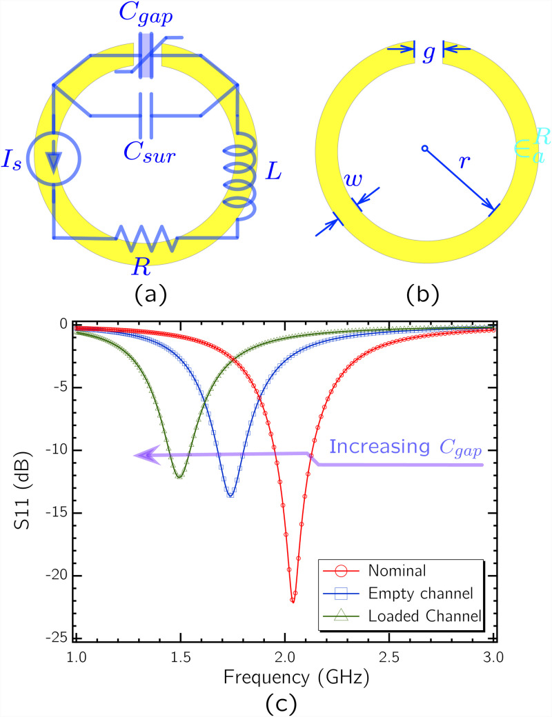
Several metamaterial-inspired electromagnetic resonator shapes were studied in the literature for various applications.47,48 Due to its ability to concentrate electric fields in a single sensitive area at its gap and its simple structure, the basic circular SRR shown in Fig. 1 was used in this work. It is simply a circular conductive path with a single gap on it. Electrical behavior of the SRR can be modeled with an equivalent resistance , capacitance , and inductance . The capacitance component has two main contributions from gap capacitance and surface capacitance as shown in Eq. (1),49
| (1) |
FIG. 1.
(a) circuit model corresponding to the SRR structure. is shown as a variable capacitor in order to represent its role in sensing of small volume reagents. (b) Dimensions associated with the SRR. (c) SPICE simulation of the circuit based on parameter values derived from the selected geometry, based on the analytical model in Ref. 50.
The circuit model parameters are inherent to SRR geometry—defined by gap width , conductive path width , circle inner radius , and conductor thickness (not shown in Fig. 1)—and material properties. Analytical models were developed in the literature linking the quantities to the geometry parameters of the SRR.50 Following these models, the resonance frequency and of the SRR can be engineered based on Eqs. (2) and (3),49
| (2) |
| (3) |
Here, a higher can potentially concentrate the electric field in a single region of the SRR and increase the sensitivity. This is due to the fact that the sensing of the small volume biological reagent present at the gap is tracked by the change of relative electric permittivity around the gap and, therefore, the change of itself. The more contribution has in , the more pronounced will be the change in , based on the relation in (2). However, based on (3), too high a total can cause a deterioration in , which presents a design tradeoff.
Any sensing action with electromagnetic resonator structures requires them to be subject to electromagnetic waves. Microstrip lines and various antenna configurations have been used for this reason.36,51,52 In this work, the SRRs are coupled to individual loop antennas surrounding them. Use of loop antennas allows the design to be free of ground planes, reducing the fabrication and setup complexity. Moreover, with loop antennas, measurements can be done by using a single port per single resonator. Locating resonators co-centrically within the loop also has the advantage of maximizing the magnetic coupling between the antennas and the resonators.
In many of the previously demonstrated applications, the resonators and the exciting elements were patterned on 35 m-thick Cu-plated flame retardant 4 (FR4) substrates. Reported nominal (in-air) of SRRs fabricated as such can exceed 100.52,53 However, is observed to reduce with further dielectric loading, especially in the context of sensing with liquid samples. Fabrication with a more conductive metal, such as Au, and a substrate with lower dielectric loss, such as glass, is demonstrated in this work to maintain high while demonstrating microfabrication compatibility.
2. Geometry and design
Electromagnetic resonators demonstrated for the sensing of liquid samples are usually designed at microwave regime. Geometric sizes associated with this frequency regime are easy to handle and therefore suitable for portable applications. Going further down in size and working at mm wave and THz frequencies have the drawback of reduced reliability, since at high frequencies the effective of the liquid samples will be changed due to increased absorption.25
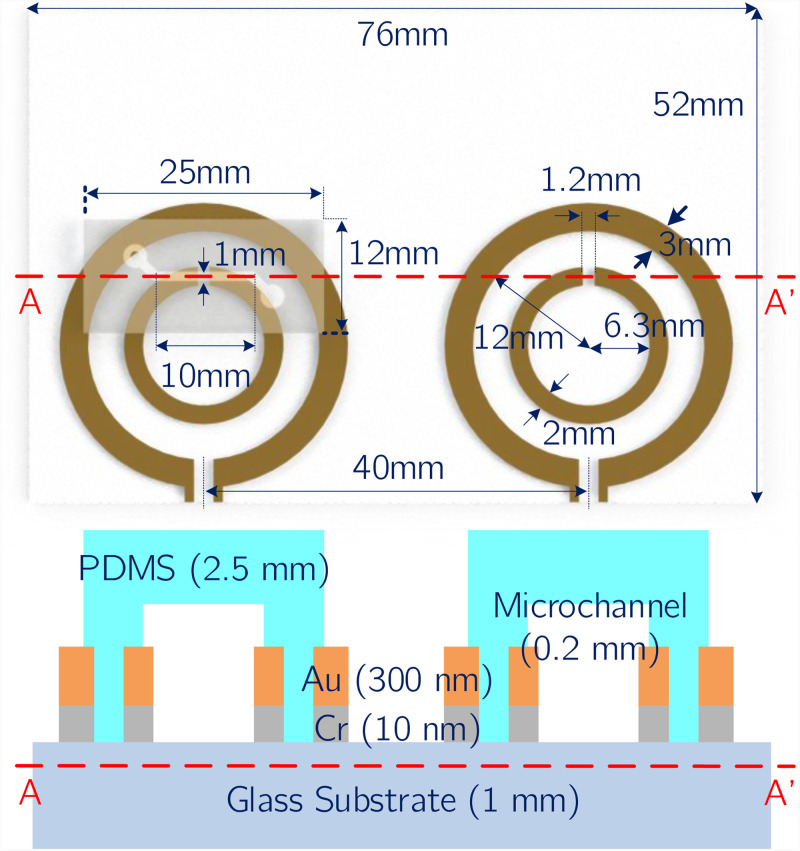
Based on this principle, an SRR with at 2 GHz was designed to be fabricated on a glass substrate with a thickness of 1 mm. The SRR and the loop antenna have the geometric dimensions shown in Fig. 2. For these dimensions, the circuit derived from the analytical model was simulated in SPICE for different dielectric loads in order to demonstrate the change in with different dielectric loads. SPICE simulated s11 spectra are plotted in Fig. 1(c), where conductive losses are arbitrarily assigned. During the design step, the conductor thickness for the resonator and the antenna after vapor deposition is taken as 300 nm.
FIG. 2.
(Top) Geometric dimensions of the selected SRR design, loop antenna, microchannel, and glass substrate. Note that the microchannel on the right hand side was not drawn for visual clarity. (Bottom) Cross-sectional view of the sensor structure across the A–A line marked on the top figure. Layer composition and the corresponding layer thickness of the elements forming the microfluidic lab-on-chip system (not to scale).
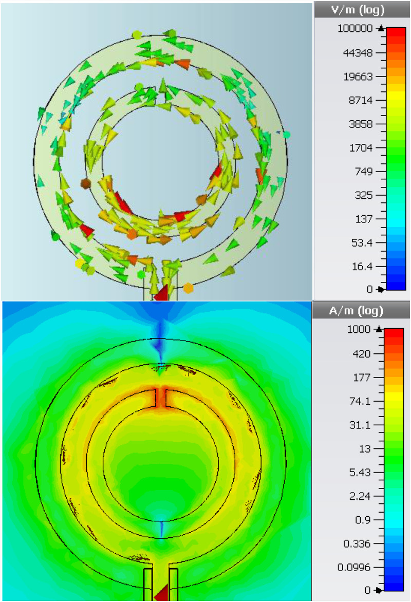
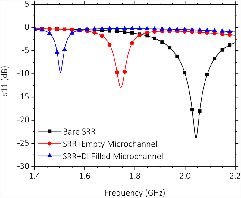
The electromagnetic solver CST Microwave Studio was used to more accurately simulate the resonance behavior of the SRR coupled with the loop antenna. Simulation results depicted in Fig. 3 show the circulating surface current and the absolute value of the electric field at resonance, which is at 2.04 GHz. The high concentration of electric field around the gap region confirm its high sensitivity. Next, reflection spectra for bare SRR, SRR integrated with empty microchannel, and SRR integrated with empty microchannel retaining de-ionized (DI) water were computed in the same simulation environment. The results shown in Fig. 4 confirm a progressive shift of due to increased dielectric loading, which increases effective capacitance of the resonator. Higher of the PDMS material causes a shift of the resonance frequency to 1.74 GHz from the original resonance frequency of 2.04 GHz, even when the microchannel is kept empty. Introduction of DI water to the microchannel introduces additional dielectric loading, shifting the resonance frequency further down to 1.5 GHz. In the sensor system demonstrated in this work, a pair of identical SRRs discussed above, coupled to their individual loop antennas, are used to perform double measurements. In such a scheme, the measuring SRR performs the actual sensing, while the reference SRR performs the measurement of ambient variations.
FIG. 3.
CST Microwave Studio simulation results for an SRR/loop antenna couple. Excitation was done with a discrete port defined at the loop antenna port. (Top) Induced circulating surface currents. (Bottom) Absolute value of the electric field observed on substrate surface. High concentration in the gap region points at high sensitivity potential.
FIG. 4.
Simulated reflection (s11) response of a single SRR/loop antenna couple. Spectra are shown for the simulated cases in which the SRR is bare, integrated with an empty microchannel, and the integrated with a microchannel filled with DI water.
B. Microchannels
Two identical microchannels were used in the sensor system to be integrated with the individual measuring and reference SRRs. They are made of PDMS, which is widely used in microchannel fabrication. Main advantages of PDMS microchannels in this regard are their low cost and low thermal conductivity. Their elastic and biocompatible nature also makes them attractive for more specialized applications of microfluidics.1 PDMS can also be bonded directly on the glass substrates the SRRs were fabricated on. This allows direct contact of the sample in microchannel with the resonator gap, increasing the sensitivity. Dimensions of the selected microchannel design are shown in Fig. 2. Note that the microchannel on the right hand side was not drawn in this figure for visual clarity.
C. Fabrication
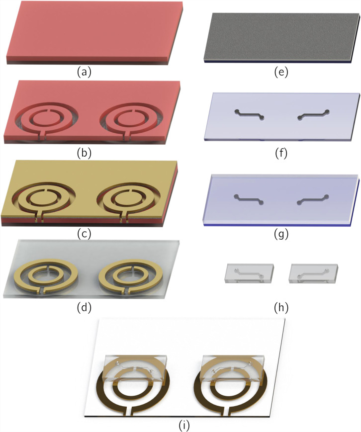
Fabrication of the microfluidic lab-on-chip system was done with conventional microfabrication techniques. For the patterning of the SRRs and the loop antennas, a standard lift-off procedure was followed. After the substrate was cleaned with isopropyl alcohol (IPA), acetone, and DI water, a surface treatment was performed with TI PRIME, which was spin-coated at 4000 rpm for 45 s and was baked on a hotplate at 110 C for 2 min. Following the treatment, AZ 5214 photoresist was spin-coated on the surface at 4000 rpm and was baked on the hotplate at 120 C for 5 min. After the UV exposure, a reverse bake at 120 C for 2 min was performed, followed by a second exposure. After the development, physical vapor deposition was used to sputter a 300 nm layer of Au on top of a 10 nm layer of Cr, which acts as an adhesive layer. Following the removal of sacrificial layers in acetone, patterning of the SRRs and loop antennas was finalized. Fabrication steps regarding this procedure were shown in Figs. 5(a)–5(d).
FIG. 5.
Fabrication process steps for the [(a)–(d)] patterning of SRRs and loop antennas, [(e)–(h]) the microchannels, and (i) the bonding of microchannels onto the surface of the glass substrate and SRR/loop antenna couples. (a) Spin-coating of photoresist on the glass substrate following surface treatment. (b) Photolithographic patterning of the photoresist. (c) Physical vapor deposition of adhesion promoting 10 nm Cr, followed by deposition of 300 nm Au. (d) Removal of sacrificial elements. (e) Spin-coating of SU-8 on silicon wafer. (f) Patterning of SU-8 with conventional photolithography to form the casting mold. (g) Pouring of the PDMS/curing agent mixture onto the mold, followed by degassing and curing. (h) Cutting and puncturing of the formed microchannels. (i) Methanol mediated alignment of microchannels on resonators and plasma activation bonding of microchannels on glass substrates.
Microchannels were fabricated via casting. A master mold of SU-8 for casting was created with conventional photolithography processes. Two layers of SU-8 3050 negative photoresist were spin-coated on a silicon wafer with an equal thickness of 100 m to achieve a total thickness of 200 m. PDMS (Slygard 184, Dow Corning, USA) was mixed with 10% by weight of curing agent. The mixture was poured onto SU-8 mold and was degassed in a vacuum chamber. After that, it was cured and solidified at 90 C for 30 min on a hotplate. Formed PDMS microchannels were then cut and punctured to create the inlet/outlet holes. Relevant fabrication steps are shown in Figs. 5(e)–5(h).
Plasma activated bonding process was applied to PDMS microchannels and the glass substrate, after the SRRs and antennas were formed on it. Droplets of methanol were used to create a sliding layers between the microchannels and the glass substrate for convenient alignment. Aligned microchannels and substrate are placed in a vacuum oven at 50 C for 15 min. With the evaporation of methanol, a stable bonding was achieved. Finalized platform after bonding is schematized in Fig. 5(i).
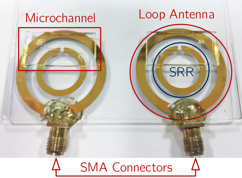
Following the bonding of the microchannels on glass substrates, SubMiniature Version A (SMA) connectors were soldered using lead-free (Sn/Cu) solder material and methods to loop antenna ports directly. To increase the mechanical stability during measurements, the solder nodes were sealed with epoxy. The fabricated microfluidic lab-on-chip system is shown in Fig. 6.
FIG. 6.
Photograph showing the fabricated sensor system with the SMA connectors added. The twin structure approach is necessary for the application of differential measurement. Solder contacts are sealed with epoxy adhesive to reduce mechanical stress.
III. MEASUREMENT RESULTS
A. Measurement setup
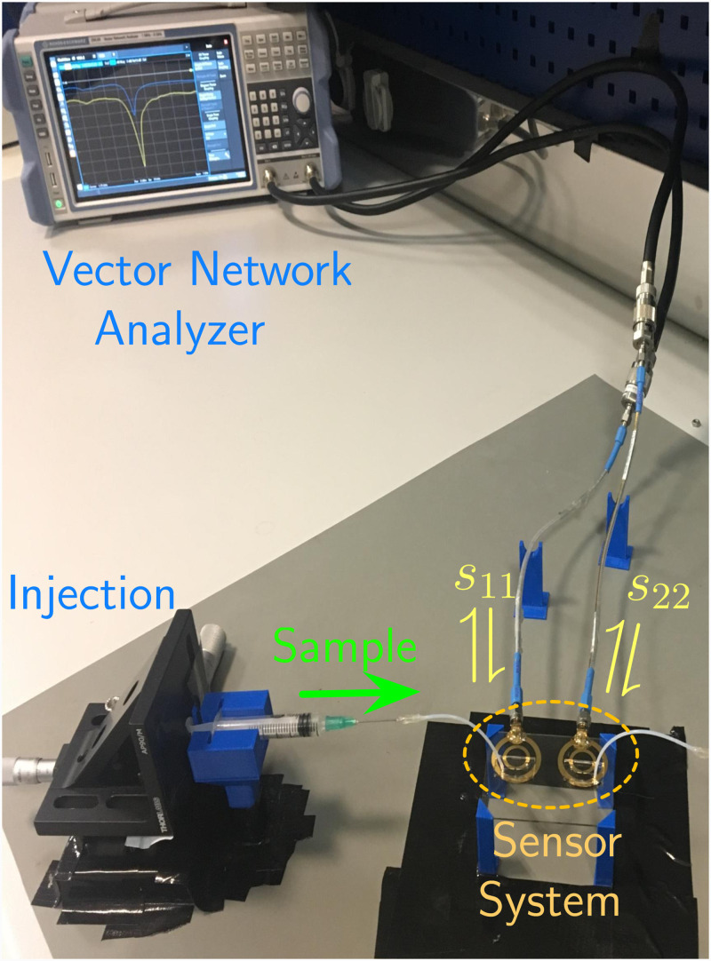
A custom design 3D holder platform was fabricated with 3D printing techniques. This holder platform was used to stabilize the microfluidic lab-on-chip system. During the measurements, liquid samples were applied with commercially available syringes, connected to the microchannels via Teflon tubes of 0.5 mm diameter. Syringes were also fixed by custom design 3D platforms and were operated through mm per rotation stages, allowing for sensitive manipulation. The samples were injected to the microchannels with this equipment until the channel was fully occupied with the sample, at which point the sample flow was terminated. The relevant measurement for the static sample was recorded 10 s after flow termination. Following the recording, the sample was removed from the microchannels via the same equipment. This procedure was repeated for every consecutive measurement. The readings were done in the form of measurement of the reflection spectra of the SRR-loaded loop antennas, where s11 and s22 parameters corresponded to readings from measuring and reference SRRs, respectively. Observation of the reflection spectra was done with a vector network analyzer (Rohde & Schwarz—ZVB4). The measurement setup is shown in Fig. 7.
FIG. 7.
Photograph showing the measurement setup and mechanism. Custom 3D printed holders were used in the setup to increase measurement stability. Liquid samples were injected with syringes driven by a manually actuated sensitive injection mechanism through Teflon tubes. Reflection spectra corresponding to measuring resonator (s11) and the reference resonator (s22) are observed in the vector network analyzer.
B. Liquid dielectric loading
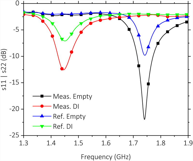
Measured spectra for unloaded microchannels and DI water-loaded microchannels are shown in Fig. 8. Results demonstrate similar at 1.74 GHz for both unloaded SRRs, while the measuring SRR shifts to a lower frequency of 1.45 GHz, as expected from the simulations. Error of for the reference SRR with respect to measurement SRR is 0.1% and 0.4% for unloaded and DI water-loaded cases, respectively. Small offset values could be achieved as a result of microfabrication techniques ensuring a more effective double measurement. A of 124 for the measuring SRR is confirmed even though the sensor is presently loaded with the PDMS microchannel block and the Au conductor of 300 nm thickness is much thinner than the commonly used Cu on FR4 approaches, which typically has 35 m thickness. The value obtained with this approach is around 100 for the microwave resonator structures with similar dimensions. Further reduction of a potentially higher is due to the fact that the present metal thickness is lower than the skin depth of Au. At the operation frequencies at 2.0 GHz, 1.75 GHz, and 1.45 GHz, the skin depth of Au is 1.68 m, 1.80 m, and 1.95 m, respectively. Staying below the skin depth increases resistive losses and in effect reduces the SRR quality factor.
FIG. 8.
Measured reflection spectra (s11, s22) for measuring and reference SRRs. Microchannels are kept empty and filled with DI water while simultaneous measurements are conducted. Measuring SRR achieves with an empty microchannel on it.
C. Glucose solution loading
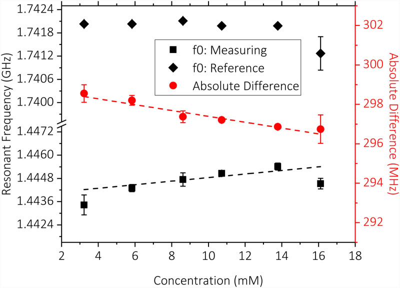
As the next step, glucose solutions with various concentrations (3.2–16.1 mM) were introduced to measuring SRR while the reference SRR was kept empty and measured the ambient variations. Three measurements at each concentration level were taken. The averages of the measurements and the absolute difference between the measuring and reference readings are shown in Fig. 9. Error bars were added to show standard deviations of measurements. Trendline fits were added to the averages of the measuring SRR and the absolute difference readings. Comparison of these trendline fits shows significant linearity improvement owing to the difference measurement approach () compared to the standalone measuring SRR reading (). Data reveal an absolute sensitivity to glucose concentration levels of 0.16 MHz/mM.
FIG. 9.
Resonance frequency of the measuring and reference SRRs and their difference vs glucose concentration levels. Trendline fits indicate increased linearity of the difference reading compared to standalone measuring SRR reading. Measurement sensitivity is determined to be 0.16 MHz/mM.
IV. CONCLUSION
This paper presented a metamaterial-inspired microwave resonator-based microfluidic lab-on-chip system developed for sensing of liquid samples. The overall system was fabricated via conventional microfabrication techniques with materials commonly used for similar sensor systems designed for microfluidics and healthcare applications. Its ability to sense the material changes around the sensitive gap region was shown with simulations and measurement results. Measurement results related to shifts under dielectric loading are demonstrated to be in agreement with theoretical expectations and simulation results. Results also clearly indicated the performance improvement provided by the addition of the reference SRR. Highly increased linearity of the difference reading with respect to glucose concentration proves the effectiveness of reference SRR in detection of the ambient variations.
A comparison of the sensor system described in this work with the state of the art is presented in Table I. The works shown in the table present microwave resonator-based systems, incorporating microfluidic elements or structures acting as liquid containers, developed for detection of glucose in aqueous solutions. These systems were tested within various ranges of glucose concentrations and some track the change of the magnitude of the reflection/spectra response, instead of the change of . Of the sensor systems listed in the table, only the one presented in this work features resonators that are not in electrically conductive contact with the measurement ports, making them promising for contactless sensing applications.
TABLE I.
Comparison of microwave resonator-based sensors presented in the literature for the detection of glucose concentration in aqueous solutions.
It is seen that the sensitivity of the sensor to glucose in aqueous solutions, which is expressed in this work as the shift in per change in concentration, was kept high in the order of similar sensors shown in the literature,41,42 which is related to high of the measuring SRR. This was possible due to the selected geometry for the SRR and the maintenance of a high . Implementation of a resonator geometry providing a high compared to ensures that the shift in is more directly related to the presence of the sample. The use of SRR is in alignment with this approach. The effect is more pronounced since the sample is confined on the gap region due to the incorporation of the microchannel. A high is also instrumental for higher sensitivity, since a sharper dip in the reflection spectra is beneficial for the resolution of smaller shifts resulting from smaller concentration changes. Limit of detection and reading resolution depends on the resolution of the measurement equipment used, which in this case was a vector network analyzer.
In its current state, the presented sensor system has limited specificity. This is related to the fact that the system does not incorporate any element selective to a certain reagent. It is possible to advance the sensor system to a reagent specific biosensor by the functionalization of the sensor surface with biospecific elements. In fact, the materials chosen for the fabrication of the system are widely used for functionalization in various applications presented in the literature.59–62 Microwave resonator-based sensing can still be applied in the presence of reagent specific elements, since any binding activity or related chemical reaction will also result in a change of the dielectric properties of the liquid sample. The system can be further developed by the integration of the SRR/antenna system with oscillator network such as the one demonstrated in Ref. 63 in order to increase system portability further. In such a case, the readings will be performed through observation of the difference of oscillator frequencies. Miniaturization and integration with electronics potential of metamaterial-inspired resonators give them a clear advantage in this respect.
ACKNOWLEDGMENTS
This research was funded by the Turkish Academy of Sciences (TUBA).
DATA AVAILABILITY
The data that support the findings of this study are available within the article.
REFERENCES
- 1.Hou X., Zhang Y. S., Santiago G. T.-D., Alvarez M. M., Ribas J., Jonas S. J., Weiss P. S., Andrews A. M., Aizenberg J., and Khademhosseini A., “Interplay between materials and microfluidics,” Nat. Rev. Mater. 2, 17016 (2017). 10.1038/natrevmats.2017.16 [DOI] [PMC free article] [PubMed] [Google Scholar]
- 2.Mostafalu P., Akbari M., Alberti K. A., Xu Q., Khademhosseini A., and Sonkusale S. R., “A toolkit of thread-based microfluidics, sensors, and electronics for 3D tissue embedding for medical diagnostics,” Microsyst. Nanoeng. 2, 16039 (2016). 10.1038/micronano.2016.39 [DOI] [PMC free article] [PubMed] [Google Scholar]
- 3.Kenry, Yeo J. C., and Lim C. T., “Emerging flexible and wearable physical sensing platforms for healthcare and biomedical applications,” Microsyst. Nanoeng. 2, 16043 (2016). 10.1038/micronano.2016.43 [DOI] [PMC free article] [PubMed] [Google Scholar]
- 4.Chen J., Guo H., Zheng J., Huang Y., Liu G., Hu C., and Wang Z. L., “Self-powered triboelectric micro liquid/gas flow sensor for microfluidics,” ACS Nano 10, 8104–8112 (2016). 10.1021/acsnano.6b04440 [DOI] [PubMed] [Google Scholar]
- 5.Altinagac E., Taskin S., and Kizil H., “Single cell array impedance analysis in a microfluidic device,” J. Phys. Conf. Ser. 757, 012010 (2016). 10.1088/1742-6596/757/1/012010 [DOI] [Google Scholar]
- 6.Luka G., Ahmadi A., Najjaran H., Alocilja E., DeRosa M., Wolthers K., Malki A., Aziz H., Althani A., and Hoorfar M., “Microfluidics integrated biosensors: A leading technology towards lab-on-a-chip and sensing applications,” Sensors 15, 30011–30031 (2015). 10.3390/s151229783 [DOI] [PMC free article] [PubMed] [Google Scholar]
- 7.Riahi R., Tamayol A., Shaegh S. A. M., Ghaemmaghami A. M., Dokmeci M. R., and Khademhosseini A., “Microfluidics for advanced drug delivery systems,” Curr. Opin. Chem. Eng. 7, 101–112 (2015). 10.1016/j.coche.2014.12.001 [DOI] [PMC free article] [PubMed] [Google Scholar]
- 8.Rackus D. G., Shamsi M. H., and Wheeler A. R., “Electrochemistry, biosensors and microfluidics: A convergence of fields,” Chem. Soc. Rev. 44, 5320–5340 (2015). 10.1039/C4CS00369A [DOI] [PubMed] [Google Scholar]
- 9.Yang K., Peretz-Soroka H., Liu Y., and Lin F., “Novel developments in mobile sensing based on the integration of microfluidic devices and smartphones,” Lab Chip 16, 943–958 (2016). 10.1039/C5LC01524C [DOI] [PMC free article] [PubMed] [Google Scholar]
- 10.Pires N. M. M., Dong T., Hanke U., and Hoivik N., “Recent developments in optical detection technologies in lab-on-a-chip devices for biosensing applications,” Sensors 14, 15458–15479 (2014). 10.3390/s140815458 [DOI] [PMC free article] [PubMed] [Google Scholar]
- 11.Son M., Kim D., Ko H. J., Hong S., and Park T. H., “A portable and multiplexed bioelectronic sensor using human olfactory and taste receptors,” Biosens. Bioelectron. 87, 901–907 (2017). 10.1016/j.bios.2016.09.040 [DOI] [PubMed] [Google Scholar]
- 12.Zhang W., Guo S., Pereira Carvalho W. S., Jiang Y., and Serpe M. J., “Portable point-of-care diagnostic devices,” Anal. Methods 8, 7847–7867 (2016). 10.1039/C6AY02158A [DOI] [Google Scholar]
- 13.Altintas Z., Akgun M., Kokturk G., and Uludag Y., “A fully automated microfluidic-based electrochemical sensor for real-time bacteria detection,” Biosens. Bioelectron. 100, 541–548 (2018). 10.1016/j.bios.2017.09.046 [DOI] [PubMed] [Google Scholar]
- 14.Lee G., Lee J., Kim J., Choi H. S., Kim J., Lee S., and Lee H., “Single microfluidic electrochemical sensor system for simultaneous multi-pulmonary hypertension biomarker analyses,” Sci. Rep. 7, 7545 (2017). 10.1038/s41598-017-06144-9 [DOI] [PMC free article] [PubMed] [Google Scholar]
- 15.Martín A., Kim J., Kurniawan J. F., Sempionatto J. R., Moreto J. R., Tang G., Campbell A. S., Shin A., Lee M. Y., Liu X., and Wang J., “Epidermal microfluidic electrochemical detection system: Enhanced sweat sampling and metabolite detection,” ACS Sens. 2, 1860–1868 (2017). 10.1021/acssensors.7b00729 [DOI] [PubMed] [Google Scholar]
- 16.Shin S. R., Zhang Y. S., Kim D.-J., Manbohi A., Avci H., Silvestri A., Aleman J., Hu N., Kilic T., Keung W., Righi M., Assawes P., Alhadrami H. A., Li R. A., Dokmeci M. R., and Khademhosseini A., “Aptamer-based microfluidic electrochemical biosensor for monitoring cell-secreted trace cardiac biomarkers,” Anal. Chem. 88, 10019–10027 (2016). 10.1021/acs.analchem.6b02028 [DOI] [PMC free article] [PubMed] [Google Scholar]
- 17.Yang H. and Gijs M. A. M., “Micro-optics for microfluidic analytical applications,” Chem. Soc. Rev. 47, 1391–1458 (2018). 10.1039/C5CS00649J [DOI] [PubMed] [Google Scholar]
- 18.Tahirbegi I. B., Ehgartner J., Sulzer P., Zieger S., Kasjanow A., Paradiso M., Strobl M., Bouwes D., and Mayr T., “Fast pesticide detection inside microfluidic device with integrated optical pH, oxygen sensors and algal fluorescence,” Biosens. Bioelectron. 88, 188–195 (2017). 10.1016/j.bios.2016.08.014 [DOI] [PubMed] [Google Scholar]
- 19.Weng X., Gaur G., and Neethirajan S., “Rapid detection of food allergens by microfluidics ELISA-based optical sensor,” Biosensors 6, 24 (2016). 10.3390/bios6020024 [DOI] [PMC free article] [PubMed] [Google Scholar]
- 20.Jie Yin M., Huang B., Gao S., Zhang A. P., and Ye X., “Optical fiber LPG biosensor integrated microfluidic chip for ultrasensitive glucose detection,” Biomed. Opt. Express 7, 2067–2077 (2016). 10.1364/BOE.7.002067 [DOI] [PMC free article] [PubMed] [Google Scholar]
- 21.Burger R., Amato L., and Boisen A., “Detection methods for centrifugal microfluidic platforms,” Biosens. Bioelectron. 76, 54–67 (2016). 10.1016/j.bios.2015.06.075 [DOI] [PubMed] [Google Scholar]
- 22.RoyChoudhury S., Rawat V., Jalal A. H., Kale S., and Bhansali S., “Recent advances in metamaterial split-ring-resonator circuits as biosensors and therapeutic agents,” Biosens. Bioelectron. 86, 595–608 (2016). 10.1016/j.bios.2016.07.020 [DOI] [PubMed] [Google Scholar]
- 23.Kling A., Chatelle C., Armbrecht L., Qelibari E., Kieninger J., Dincer C., Weber W., and Urban G., “Multianalyte antibiotic detection on an electrochemical microfluidic platform,” Anal. Chem. 88, 10036–10043 (2016). 10.1021/acs.analchem.6b02294 [DOI] [PubMed] [Google Scholar]
- 24.Zarifi M. H., Sadabadi H., Hejazi S. H., Daneshmand M., and Sanati-Nezhad A., “Noncontact and nonintrusive microwave-microfluidic flow sensor for energy and biomedical engineering,” Sci. Rep. 8, 139 (2018). 10.1038/s41598-017-18621-2 [DOI] [PMC free article] [PubMed] [Google Scholar]
- 25.Salim A. and Lim S., “Review of recent metamaterial microfluidic sensors,” Sensors 18, 232 (2018). 10.3390/s18010232 [DOI] [PMC free article] [PubMed] [Google Scholar]
- 26.Wiltshire B., Mirshahidi K., Golovin K., and Zarifi M. H., “Robust and sensitive frost and ice detection via planar microwave resonator sensor,” Sens. Actuators B 301, 126881 (2019). 10.1016/j.snb.2019.126881 [DOI] [Google Scholar]
- 27.Moghadas H. and Mushahwar V. K., “Passive microwave resonant sensor for detection of deep tissue injuries,” Sens. Actuators B 277, 69–77 (2018). 10.1016/j.snb.2018.08.084 [DOI] [Google Scholar]
- 28.Rydosz A., Maciak E., Wincza K., and Gruszczynski S., “Microwave-based sensors with phthalocyanine films for acetone, ethanol and methanol detection,” Sens. Actuators B 237, 876–886 (2016). 10.1016/j.snb.2016.06.168 [DOI] [Google Scholar]
- 29.Chen T., Li S., and Sun H., “Metamaterials application in sensing,” Sensors 12, 2742 (2012). 10.3390/s120302742 [DOI] [PMC free article] [PubMed] [Google Scholar]
- 30.Bogaerts W., De Heyn P., Van Vaerenbergh T., De Vos K., Kumar Selvaraja S., Claes T., Dumon P., Bienstman P., Van Thourhout D., and Baets R., “Silicon microring resonators,” Laser Photon. Rev. 6, 47–73 (2012). 10.1002/lpor.201100017 [DOI] [Google Scholar]
- 31.Camli B., Kusakci E., Lafci B., Salman S., Torun H., and Yalcinkaya A. D., “Cost-effective, microstrip antenna driven ring resonator microwave biosensor for biospecific detection of glucose,” IEEE J. Sel. Top. Quantum Electron. 23, 404–409 (2017). 10.1109/JSTQE.2017.2659226 [DOI] [Google Scholar]
- 32.Xu W., Xie L., and Ying Y., “Mechanisms and applications of terahertz metamaterial sensing: A review,” Nanoscale 9, 13864–13878 (2017). 10.1039/C7NR03824K [DOI] [PubMed] [Google Scholar]
- 33.Bakir M., Karaaslan M., Unal E., Akgol O., and Sabah C., “Microwave metamaterial absorber for sensing applications,” Opto-Electron. Rev. 25, 318–325 (2017). 10.1016/j.opelre.2017.10.002 [DOI] [Google Scholar]
- 34.Kim N.-Y., Adhikari K. K., Dhakal R., Chuluunbaatar Z., Wang C., and Kim E.-S., “Rapid, sensitive, and reusable detection of glucose by a robust radiofrequency integrated passive device biosensor chip,” Sci. Rep. 5, 7807 (2015). 10.1038/srep07807 [DOI] [PMC free article] [PubMed] [Google Scholar]
- 35.Sabah C., Dincer F., Karaaslan M., Bakir M., Unal E., and Akgol O., “Biosensor applications of chiral metamaterials for marrowbone temperature sensing,” J. Electromagn. Waves Appl. 29, 2393–2403 (2015). 10.1080/09205071.2015.1084894 [DOI] [Google Scholar]
- 36.Torun H., Cagri Top F., Dundar G., and Yalcinkaya A. D., “An antenna-coupled split-ring resonator for biosensing,” J. Appl. Phys. 116, 124701 (2014). 10.1063/1.4896261 [DOI] [Google Scholar]
- 37.Ekmekci E. and Turhan-Sayan G., “Multi-functional metamaterial sensor based on a broad-side coupled SRR topology with a multi-layer substrate,” Appl. Phys. A 110, 189–197 (2013). 10.1007/s00339-012-7113-1 [DOI] [Google Scholar]
- 38.Lee H.-J., Lee J.-H., Choi S., Jang I.-S., Choi J.-S., and Jung H.-I., “Asymmetric split-ring resonator-based biosensor for detection of label-free stress biomarkers,” Appl. Phys. Lett. 103, 053702 (2013). 10.1063/1.4816440 [DOI] [Google Scholar]
- 39.Schueler M., Mandel C., Puentes M., and Jakoby R., “Metamaterial inspired microwave sensors,” IEEE Microw. Mag. 13, 57–68 (2012). 10.1109/MMM.2011.2181448 [DOI] [Google Scholar]
- 40.La Spada L., Bilotti F., and Vegni L., “Metamaterial resonator arrays for organic and inorganic compound sensing,” Proc. SPIE 8306, 83060I (2011). 10.1117/12.912267 [DOI] [Google Scholar]
- 41.Camli B., Altinagac E., Kizil H., Torun H., Dundar G., and Yalcinkaya A. D., “Loop antenna driven double microwave resonator-based sensors incorporating PDMS microchannels on glass substrates,” Proceedings 2, 1064 (2018). 10.3390/proceedings2131064 [DOI] [Google Scholar]
- 42.Ebrahimi A., Withayachumnankul W., Al-Sarawi S. F., and Abbott D., “Microwave microfluidic sensor for determination of glucose concentration in water,” in Microwave Symposium (MMS), 2015 IEEE 15th Mediterranean (IEEE, 2015), pp. 1–3.
- 43.Jaruwongrungsee K., Waiwijit U., Withayachumnankul W., Maturos T., Phokaratkul D., Tuantranont A., Wlodarski W., Martucci A., and Wisitsoraat A., “Microfluidic-based split-ring-resonator sensor for real-time and label-free biosensing,” Procedia Eng. 120, 163–166 (2015). 10.1016/j.proeng.2015.08.595 [DOI] [Google Scholar]
- 44.Camli B., Torun H., Dundar G., and Yalcinkaya A. D., “Reference-incorporating microwave resonator-based sensors for biological sensing applications,” Proceedings 1, 542 (2017). 10.3390/proceedings1040542 [DOI] [Google Scholar]
- 45.Vélez P., Su L., Grenier K., Mata-Contreras J., Dubuc D., and Martín F., “Microwave microfluidic sensor based on a microstrip splitter/combiner configuration and split ring resonators (SRRS) for dielectric characterization of liquids,” IEEE Sens. J. 17, 6589–6598 (2017). 10.1109/JSEN.2017.2747764 [DOI] [Google Scholar]
- 46.Li O.-L., Tong Y.-L., Chen Z.-G., Liu C., Zhao S., and Mo J.-Y., “A glass/PDMS hybrid microfluidic chip embedded with integrated electrodes for contactless conductivity detection,” Chromatographia 68, 1039–1044 (2008). 10.1365/s10337-008-0808-y [DOI] [Google Scholar]
- 47.Bage A. and Das S., “Studies of some non-conventional split ring and complementary split ring resonators for waveguide band stop band pass filter application,” in 2013 International Conference on Microwave and Photonics (ICMAP) (IEEE, 2013), pp. 1–5.
- 48.Baena J. D., Bonache J., Martin F., Sillero R. M., Falcone F., Lopetegi T., Laso M. A. G., Garcia-Garcia J., Gil I., Portillo M. F., and Sorolla M., “Equivalent-circuit models for split-ring resonators and complementary split-ring resonators coupled to planar transmission lines,” IEEE Trans. Microw. Theor. Tech. 53, 1451–1461 (2005). 10.1109/TMTT.2005.845211 [DOI] [Google Scholar]
- 49.Nilsson J. and Riedel S., in Electric Circuits, Addison-Wesley Series in Electrical and Computer Engineering (Addison-Wesley, 1996).
- 50.Sydoruk O., Tatartschuk E., Shamonina E., and Solymar L., “Analytical formulation for the resonant frequency of split rings,” J. Appl. Phys. 105, 014903 (2009). 10.1063/1.3056052 [DOI] [Google Scholar]
- 51.Seo Y., Memon M. U., and Lim S., “Microfluidic eighth-mode substrate-integrated-waveguide antenna for compact ethanol chemical sensor application,” IEEE Trans. Antennas Propag. 64, 3218–3222 (2016). 10.1109/TAP.2016.2559581 [DOI] [Google Scholar]
- 52.Withayachumnankul W., Jaruwongrungsee K., Tuantranont A., Fumeaux C., and Abbott D., “Metamaterial-based microfluidic sensor for dielectric characterization,” Sens. Actuators A 189, 233–237 (2013). 10.1016/j.sna.2012.10.027 [DOI] [Google Scholar]
- 53.Voglhuber-Brunnmaier T., Wagner L., Diskus C., Jakoby B., and Brandl M., “Sensitivity optimization of microwave biosensors,” Procedia Eng. 168, 634–637 (2016). 10.1016/j.proeng.2016.11.232 [DOI] [Google Scholar]
- 54.Kim J., Babajanyan A., Hosvepyan A., Lee K., and Friedman B., “Microwave dielectric resonator biosensor for aqueous glucose solution,” Rev. Sci. Instrum. 79, 086107 (2008). 10.1063/1.2968115 [DOI] [PubMed] [Google Scholar]
- 55.Byford J. A., Park K. Y., and Chahal P., “Metamaterial inspired periodic structure used for microfluidic sensing,” in 2015 IEEE 65th Electronic Components and Technology Conference (ECTC) (IEEE, 2015), pp. 1997–2002.
- 56.Chretiennot T., Dubuc D., and Grenier K., “Microwave-based microfluidic sensor for non-destructive and quantitative glucose monitoring in aqueous solution,” Sensors 16, 1733 (2016). 10.3390/s16101733 [DOI] [PMC free article] [PubMed] [Google Scholar]
- 57.Harnsoongnoen S. and Wanthong A., “Coplanar waveguide transmission line loaded with electric-LC resonator for determination of glucose concentration sensing,” IEEE Sens. J. 17, 1635–1640 (2017). 10.1109/JSEN.2017.2652121 [DOI] [Google Scholar]
- 58.Jang C., Park J.-K., Lee H.-J., Yun G.-H., and Yook J.-G., “Temperature-corrected fluidic glucose sensor based on microwave resonator,” Sensors 18, 3850 (2018). 10.3390/s18113850 [DOI] [PMC free article] [PubMed] [Google Scholar]
- 59.Ansari A. and Imoukhuede P. I., “Plenty more room on the glass bottom: Surface functionalization and nanobiotechnology for cell isolation,” Nano Res. 11, 5107–5129 (2018). 10.1007/s12274-018-2177-7 [DOI] [Google Scholar]
- 60.Engel S., Fritz E.-C., and Ravoo B. J., “New trends in the functionalization of metallic gold: From organosulfur ligands to n-heterocyclic carbenes,” Chem. Soc. Rev. 46, 2057–2075 (2017). 10.1039/C7CS00023E [DOI] [PubMed] [Google Scholar]
- 61.Zhou T., Zhu Y., Li X., Liu X., Yeung K. W., Wu S., Wang X., Cui Z., Yang X., and Chu P. K., “Surface functionalization of biomaterials by radical polymerization,” Prog. Mater. Sci. 83, 191–235 (2016). 10.1016/j.pmatsci.2016.04.005 [DOI] [Google Scholar]
- 62.Kumar S., Ahlawat W., Kumar R., and Dilbaghi N., “Graphene, carbon nanotubes, zinc oxide and gold as elite nanomaterials for fabrication of biosensors for healthcare,” Biosens. Bioelectron. 70, 498–503 (2015). 10.1016/j.bios.2015.03.062 [DOI] [PubMed] [Google Scholar]
- 63.Pekçokgüler N., Dündar G., Torun H., and Yalçinkaya A. D., “A novel equivalent circuit model for split ring resonator with an application of low phase noise reference oscillator,” Integration 61, 160–166 (2018). 10.1016/j.vlsi.2017.12.004 [DOI] [Google Scholar]
Associated Data
This section collects any data citations, data availability statements, or supplementary materials included in this article.
Data Availability Statement
The data that support the findings of this study are available within the article.


