Abstract
Patients with visual field loss frequently collide with other pedestrians, with the highest risk being from pedestrians at a bearing angle of 45°. Current prismatic field expansion devices (≈30°) cannot cover pedestrians posing the highest risk and are limited by poor image quality and restricted eye scanning range (<5°). A new field expansion device: multi-periscopic prism (MPP); comprising a cascade of half-penta prisms provides wider shifting power (45°) with dramatically better image quality and wider eye scanning range (15°) is presented. Spectacles-mounted MPPs were implemented using 3D printing. The efficacy of the MPP is demonstrated using perimetry, photographic depiction, and analyses of the collision risk covered by the devices.
1. Introduction
Patients with homonymous hemianopia (HH), where one half of the visual field is blind on the same side in both eyes, or with concentric peripheral field loss (PFL), sometimes called tunnel vision, report difficulties in navigating and avoiding obstacles [1–7]. They experience increased risk of collision with other pedestrians [8] and falls due to tripping over obstacles [9], as well as difficulties in driving [10]. All these effects lead to loss of mobility and can be detrimental to patients’ independence and quality of life [3,11–15].
HH results from strokes, brain surgery, or traumatic brain injuries. There were about 6 million stroke survivors in the USA in 2010 [16]. Estimates of the proportion of stroke survivors with hemianopia range from 29% for patients with cortical stroke [17] to 50% for stroke patients referred for a vision assessment [18]. In Australia, 0.8% of people over the age of 50 have HH [19], which amounts to 800 per 100,000. With well over 100 million people over the age of 50 in the USA, the prevalence of HH is about 250 per 100,000 in the 330 million total population of the USA.
PFL is usually caused by retinitis pigmentosa, choroideremia, or glaucoma. The prevalence of retinitis pigmentosa in the population of the state of Maine was estimated as 21 per 100,000 [20]. About 8% of patients with open angle glaucoma in Sweden were identified as legally blind because of field restriction (residual central field less than 20° in diameter) [21]. The prevalence of severe sight impairment due to glaucoma in the UK is 13 per 100,000 [22].
Since a pedestrian on a collision course remains at a constant bearing angle (eccentricity) relative to the patient’s heading [23], detecting and avoiding the collision is unlikely if the pedestrian’s bearing angle is outside of the patient’s residual seeing field. The pedestrian will remain within the scotoma all the way to the collision point. Peli et al. [8] analyzed the risk of collision with pedestrians approaching from all bearing angles in crowded open walking environments, such as shopping malls and transportation terminals. In these environments, pedestrians’ movement directions are not regulated unlike when walking on a sidewalk or along indoor corridors. Peli et al. found that the highest risk is from pedestrians at a bearing of 45°. Patients with field loss are able to monitor only a small fraction of the collision risks when walking in such open environments. Lateral eye scanning towards the blind field may facilitate detection of a higher fraction of approaching pedestrians. However, it was previously found that HH [24] and PFL [24–26] patients’ lateral eye scanning was not wider than 15° and does not show adaptation to the field loss [27]. Therefore, the eye scanning is insufficient to cover pedestrians approaching at the bearing angle with the highest collision risk.
Prism devices designed to shift portions of a scene from the blind field (prism base side) to the residual seeing field are the simplest, lightest, and most cost-effective visual aids for patients with field loss. The regions of the external scene made available with such devices, part of the ‘field of view (FoV)’ of the wearer, should be distinguished from the portions of the retina upon which the images can be perceived, the ‘visual field’. Thus, prisms may increase the FoV, but not the visual field. For economy of words, we refer to the FoV expansion effect of such devices, as ‘field expansion’. Peripheral prism glasses [28] are well established as an effective field expansion device for patients with HH [2,29]. They shift two portions (upper and lower) of the blind field in the periphery onto the residual functioning visual field, enabling detection of pedestrians on impending collision courses for both HH and PFL. The upper prism is used to monitor hazards in the upper visual field, such as low tree branches and open doors of upper kitchen cabinets, while the lower prism is used to monitor potential hazards in the lower visual field. The requirements for field expansion devices have been considered and studied in HH [30–32] and PFL [33,34]. Since the maximum power of current, clinically available Fresnel prisms is only 57 prism diopters (Δ), ≈ 30° [31,32], these prisms do not provide coverage of pedestrians with the highest risk of collision approaching at a fixed bearing of 45°. Therefore, field expansion with higher power prisms is needed [32].
Resuming driving after the onset of HH is an important rehabilitation goal. On-road studies have concluded that some, but not all, patients with HH may be rated as safe to drive (for a review see [10]). Many drivers with HH do not adequately compensate with gaze scanning and thus fail to detect potential hazards approaching from the blind side [35,36]. HH drivers had low detection rates for pedestrians that appeared on their blind side at ∼90° eccentricity representing a potential hazard at intersections. Detection failures were mainly caused by insufficient scanning into the blind side [37]. These results suggest that at least 30° field expansion is necessary, which is at the very limit of the currently available 57Δ Fresnel prism.
In Fresnel peripheral prisms, the effective prism shifting power increases with the angle of incidence towards the base (blind) side. However, the power increment is bounded by total internal reflection (TIR) [31]. With 57Δ Fresnel prisms, the TIR starts at just 5° from the primary position of gaze towards the blind side. The TIR, therefore, restricts the utility of the Fresnel prism, as it represents a FoV where the prism does not transmit the desired shifted images. As the angle of incidence approaches that of the TIR, the shifted image is dimmed and severely distorted (minified), which may reduce detection performance [31,38,39]. Within the TIR range, increased visibility of spurious reflections [31] may cause false alarms. All these limitations do not adversely affect the effectiveness of the prisms in HH when the patients’ eyes are at the primary position of gaze, which is the situation for most of the time when walking. However, the TIR does prevent a potential benefit of farther expansion during eye scanning towards the blind side [31]. With PFL, the TIR that starts at 5° with 57Δ prisms severely limits the field expansion benefits of peripheral prisms even at the primary position of gaze and more so with eye scanning towards the base [34].
The severe limitation of the TIR on the functionality of the peripheral prism, especially in the case of PFL, has led us to consider a variety of designs to address this problem [31,32,38]. One approach was to reduce the effective prism power [31]. Reduced power, however, is not a desirable compromise in view of our understanding of the collision risk as a function of bearing angle. In fact, one would like to achieve higher prism shifting power, combined with fewer limitations from the TIR.
We proposed and prototyped three designs of higher power prism devices [32]. All three options also enabled wider eye scanning ranges by shifting the TIR limit farther peripherally. However, two of these designs were based on conventional prisms and thus were also affected by strong distortions, poor image quality, and insufficient prism power for the desirable 45° field expansion. The third design, a mirror-based periscopic device (MP), was an attempt to address all these issues. The MP used double reflection with two mirror surfaces to achieve a 45° deflection, and cascading pairs of mirror elements provided a 45° image deflection over a wide FoV. Since the shift was achieved mostly by reflection, the MP design provided much better image quality with fewer distortions, as well as up to 15° eye scanning range. However, the MP required a separate design for the pair of mirrors in each of the cascaded modules [40]. Despite being optically more effective, this design resulted in an impractical, bulky, and heavy structure and was difficult to manufacture (specifically due to the need to glue two silvered surfaces).
Here we report on a novel design, implementation, and initial testing of a new field expansion device the multi-periscopic prism (MPP) [41], which is mostly reflective, is compact and smaller than the MP. The MPP provides 45° (=100Δ) field expansion with much better image quality than Fresnel prisms and enables a wider eye scanning range towards the blind side by overcoming the TIR limitation. Multiple designs of MPPs for HH and PFL were prototyped using 3D printing, which facilitated design flexibility, cost effectiveness, and fast turnaround time.
2. MPP for field expansion of HH
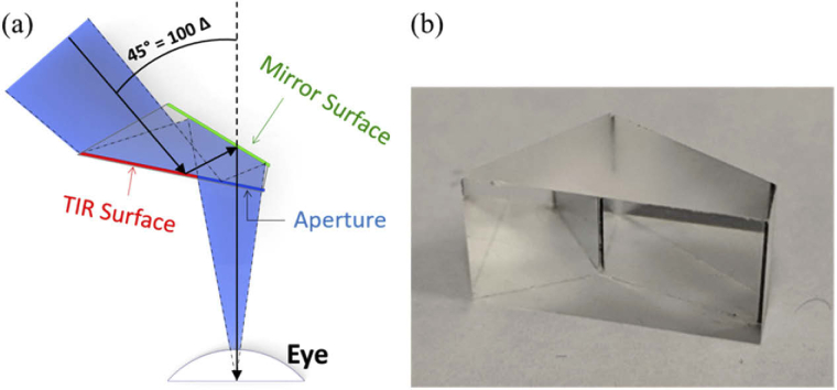
The MPP is composed of a cascade of half-penta prisms (also known as Bauernfeind prisms) [42,43], widely used as part of the image erecting system (Pechan prism) [44] in one design of Keplerian telescopes (binoculars). The half-penta prism is composed of one silvered mirror surface and one TIR mirror surface with an angle between the two surfaces of 22.5° (Fig. 1). Since the half-penta prism uses double reflections, it can be almost free of refractive effects such as prismatic distortion (horizontal minification) [45,46], image dimming [31], and contrast reduction due to the color dispersion, which limits the image quality of conventional Fresnel ophthalmic prisms [47,48].
Fig. 1.
Half-penta prism. (a) A simplified diagram of the optical effects of a single half-penta prism mounted in front of the eye of a patient with left HH, viewed from above. The surface closest to the eye is transparent. The right portion of that surface is the patient’s viewing aperture, while the left portion serves as a TIR mirror reflecting the incoming light towards the second silvered mirror surface. The light reflected from the mirror surface passes through the viewing aperture towards the eye resulting in a 45° image shift from the left to the right, as would be useful for a patient with left HH. (b) A photo of the half-penta prism used in the MPP.
Conventional prisms have a base and an apex, and the image deflection/shift is from the base side to the apex side. The MPP does not have a base in the common prism sense, but for compatibility, we refer to the deflection direction of the device as the ‘base’ direction and the opposite direction as the ‘apex’ direction. A single half-penta prism mounted in the spectacles lens in front of the eye shifts the image seen through it by 45° from the “base” direction to the “apex” direction. The aperture of an 8 mm half-penta element, used in our prototypes, placed 17 mm from the eye entrance pupil (14 mm from the cornea [49]) covers a FoV of 15°×20° (H×V). However, since the FoV through the prism and the amount of the shift should be the same to avoid a paracentral apical scotoma [30,31,50], multiple half-penta prisms are needed to provide more than 45° FoV for 45° shift.
2.1. Design of MPP as peripheral prism for HH
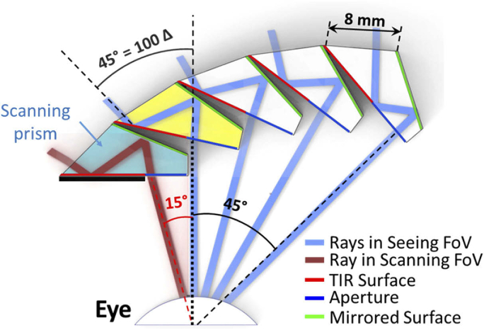
Figure 2 shows the design of MPP for HH with a cascade of half-penta prisms. To maximize the overall FoV, each half-penta prism lies behind the prior prism and is rotated relative to that prism. As a result of the peripheral position and rotation, the equivalent distance to the eye varies slightly between half-penta prisms. The half-penta prism is designed to maximize the FoV when mounted as it is used in a Keplerian telescope. This is also how it is mounted for the primary half-penta prism in the MPP (yellow prism in Fig. 2).
Fig. 2.
Optical design of MPP (cascading 5 units of 8 mm wide half-penta prisms) for left HH with “base” left. At the primary position of gaze, the seeing field is covered by the primary half-penta prism (yellow) and all the half-penta prisms to the right of it. The different blue rays, all showing a 45° shift, are separated by 15°. The leftmost half-penta prism (aqua blue) is only effective when the patient is scanning into the blind (left) side and permits an additional 15° field expansion. For each prism in the cascade, the prism immediately to the left blocks the view of the TIR surface from the eye. Only the scanning prism has to use a physical shield (black thick line) to prevent the TIR surface from acting as a refractive surface.
However, rotating and displacing the other half-penta prisms relative to the eye in the MPP may result in reductions in the FoV as illustrated in Fig. 3. This is why more than three half-penta prisms are needed to cover the required 45° FoV. To maximize the overall FoV through the MPP, each half-penta prism was individually adjusted to reduce the effects shown in Fig. 3, taking into account the pupillary translation occurring with eye rotation. The FoV through each additional half-penta prism is slightly reduced by this process (Fig. 2). Yet, the 45° deflection remains for all elements of the cascade.
Fig. 3.
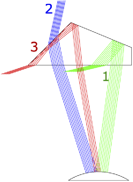
Possible FoV limitations in the half-penta prism. Displacements or rotations of the half-penta prism relative to the eye would increase or reduce one or more of the following limitations: (1) Missing the TIR at the second reflection (green rays). (2) Missing both reflections (blue rays). (3) Unwanted TIR reflection on the front surface (red rays).
As shown in Fig. 4(a), there are narrow obscuration (tunnel) scotomas between elements of the cascade (the gap between the blue ray bundles). These scotomas are small and fixed in linear width. As a result, the angular extent of such tunnel scotomas [51] at the eye shrinks rapidly with increasing object distance, making their effect negligible. The design is quite robust to variations in lateral offset (caused by variations of interpupillary distance or mounting errors). Figures 4(b) and 4(c) show constant prism power and FoV with two extreme lateral offsets from the monocular interpupillary distance. The size of the obscuration scotomas is only slightly increased with a large 5 mm shifting of the MPP from the optimal position to the right and left, respectively. Note that the ray tracing and computed perimetry diagrams used below assume pinhole pupils. However, human eyes (and the camera we use for photographic depiction, see section 2.2) have finite pupils that result in “softer” vignette effects, which reduce the obscuration scotomas to a dimmed, and sometimes lower contrast image, instead of a complete obscuration.
Fig. 4.
Ray tracing (Zemax) of the MPP for left HH. (a) Optimal position for an eye at the primary position of gaze. The same ray tracing when the MPP cascade is shifted in front of the eye by (b) 5 mm to the right and (c) 5 mm to the left. These illustrate the tolerance of the design for large shifts in spectacles frame position (a much larger shift than could reasonably be expected during normal spectacles wear).
The peripheral prism design includes upper and lower prism segments with a prism-free zone between them (Fig. 5(a)). Conventional peripheral prisms for HH are typically placed on the spectacles lens on the side of the field loss (left lens for left HH; base-out configuration) [28]. Prism segments are not included in the other lens to allow for monitoring of the field blocked by the prism itself (i.e., the apical scotoma) [30,31]. The peripheral MPP with a 45° shift requires that the MPP module for HH covers a 45° FoV on the seeing side to avoid apical scotomas at small lateral eccentricities (therefore, no apical scotoma in Fig. 5) [30,31]. To enable 15° eye scanning into the blind side [32], the MPP should extend 15° farther into the blind side covering a total 60° FoV. The need for 45° FoV on the seeing side and the limited clearance between the optical center and the nasal edge of typical spectacles prevents mounting of the MPP on the blind side lens. Therefore, we fit the peripheral MPPs for HH on the seeing side lens (base-in configuration). This still allows a 45° image shift from the lower segment with no apical scotoma (Fig. 5(a)), but farther field expansion with eye scanning is blocked by the flaring of the nose (note that scanning is blocked by the nose in most people in the lower part of the field anyway). Because of this limitation, the scanning prism is not included in the lower segment (Fig. 6).
Fig. 5.
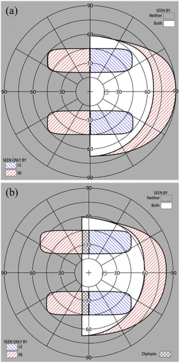
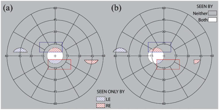
Calculated binocular perimetry (both eyes open) diagrams [30] with MPP for left HH (a) at the primary position of gaze and (b) with 10° eye scanning to the left into the blind side. The diagrams show the calculated visual field with the peripheral MPPs fitted unilaterally on the right lens for left HH (one MPP segment in the upper visual field and one MPP segment in the lower visual field). 45° of field expansion is expected with the MPPs, and also 45° wide FoV. The unilateral fitting prevents apical scotomas. Since the lower MPP segment is shorter than the upper MPP segment, field expansion beyond 45° with eye scanning is limited in the lower compared to the upper visual field. Eye scanning towards the blind side results in paracentral peripheral diplopia (marked by black crosshatching in (b)). However, the diplopic image will appear at a far retinal eccentricity, where it may not be distracting or even noticed. Yet, the additional field expansion appears near the vertical central meridian where retinal sensitivity is better and thus represents a good tradeoff.
Fig. 6.
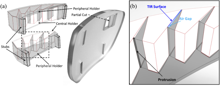
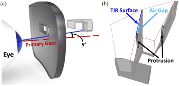
CAD design for prototype of MPP for right HH with “base” right (cascading 5 units or 4 units of 8 mm wide half-penta prisms for upper or lower MPP, respectively) mounted on the left lens. (a) A 3D-printed holder that positions and stabilizes the half-penta prisms is shown as translucent darker volumes, including central and peripheral holders and wedges positioning and separating the individual half-penta prisms. (b) A magnified view of a section of the lower MPP segment (marked by a dashed square in (a)) illustrating the details of the structure of the wedges and the protrusions used to maintain air gaps needed next to the TIR surfaces to achieve the mirror reflection effect.
The cascades of half-penta prisms were assembled in 3D-printed modules. The prototypes were mounted into carrier lenses (Fig. 6). The design of the modules was guided by three requirements: 1) Each half-penta prism had to be positioned and oriented at the required distance and angle with respect to the eye based on the ray-tracing guided design (Fig. 4). 2) An air gap was needed abutting the TIR surface for the half-penta prisms to enable reflection at the TIR surface. 3) The assembled MPP modules had to be mounted onto the carrier lenses at the positions of peripheral prisms [28].
For easy assembly, we designed the 3D-printed module in two parts, a central holder and a peripheral holder (Fig. 6(a)). The central holder, closer to the prism-free center of the carrier lens, functions as a lid to the peripheral holder. The central holder has a minimal thickness (0.5mm) to decrease obscuration by the holder while the peripheral holder has a thicker base (1 mm) needed for structural stability and includes triangle-shaped wedges (Fig. 6(b)), protruding vertically. The wedges and indented compartments guide the positioning and orientation of the half-penta prisms when assembled. The obtuse side of the triangular wedge fits flush with the mirrored surface of one half-penta prism and the opposite side of the triangular wedge creates the required air gap abutting the TIR surface. To create an air gap, the triangular wedge has a protrusion (0.25mm) at the base of the triangle that comes in contact with one end of the TIR surface. The central holder (lid) closes the air gap on the open side, and, together with the apex and the base protrusion, creates a closed cavity from all sides, reducing exposure of the TIR surface to dirt and moisture. To mount the assembled MPP segments onto the carrier lens, we designed the peripheral holders with mounting stubs (Fig. 6(a)). The carrier lens has slots cut into which the stubs are inserted and glued to mount the MPP onto the carrier lens. A partial cut is made into the carrier lens to accommodate the scanning half-penta prism and to maintain the structural integrity of the lens. The partial cut also restricts the scanning side of the MPP segment from moving into the lens and towards the eye.
We designed the 3D-printed modules to position the half-penta prisms in front of the carrier lens (rather than embedded into the carrier lens, as with current Fresnel peripheral prisms) to provide the user with the optical advantage of the carrier lens prescription. Only the scanning half-penta prism is embedded in the carrier lens and thus does not benefit from the carrier lens prescription. The central and peripheral holders are designed to match the base curve of the carrier lens, which further limits the exposure of the apertures of the half-penta prisms to dirt and moisture.
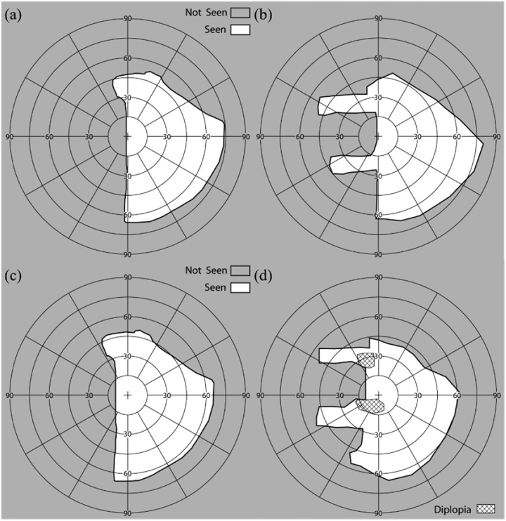
The half-penta prisms were assembled in 3D-printed modules as shown in Fig. 7. Early prototypes were mounted in carrier lenses as peripheral prisms. With the prototype peripheral MPPs on spectacles, we measured the visual field of a patient with left HH using the Goldmann perimeter with the V4e target (Fig. 8).
Fig. 7.
A 3D-printed prototype MPP upper module for left HH. (a) A translucent printed holder with base left to be mounted on the right carrier lens shown from the patient’s point of view. The dashed vertical line marks the primary position of gaze at the primary half-penta prism and at the optical center of the carrier lens. (b) Upper and lower segments of peripheral MPP prototypes mounted on the right lens for left HH (base-in) viewed from the front. Due to the limited space nasally, the lower MPP segment is shorter than the upper MPP segment (no scanning half-penta prism).
Fig. 8.
Perimetry of a patient with left HH wearing the peripheral MPPs under binocular viewing conditions. Goldmann perimetry results at primary position of gaze (a) without MPP and (b) with prototype MPP (Fig. 7). The MPP expanded the FoV up to 45° into the blind side. Goldmann perimetry results with 10° eye scanning into the blind side (c) without MPP and (d) with the MPP. The MPP enabled 10° additional expansion. Paracentral diplopia occurs with the scanning to the left, but that diplopic image is projected far into the periphery on the right and thus less noticeable.
2.2. Results of MPP for HH
All study procedures were approved by the Massachusetts Eye and Ear Infirmary Human Studies Committee and carried out in accordance with the tenets of the Declaration of Helsinki. Written, informed consent was obtained from all participants prior to the beginning of the procedures. The amount of field expansion in primary gaze, as well as the increase in field expansion and the areas of paracentral diplopia when scanning to the blind side are matched well with the calculated perimetry diagrams in Fig. 5.
Figure 9 is a photographic depiction showing the high image quality of the MPP. To correctly visualize the perceived scene through the MPP, we mounted the prototype MPP at 17 mm (a typical distance between the back of the spectacles lens and the entrance pupil of the human eye [49]) in front of the entrance pupil of a camera lens and captured photographs [52].
Fig. 9.
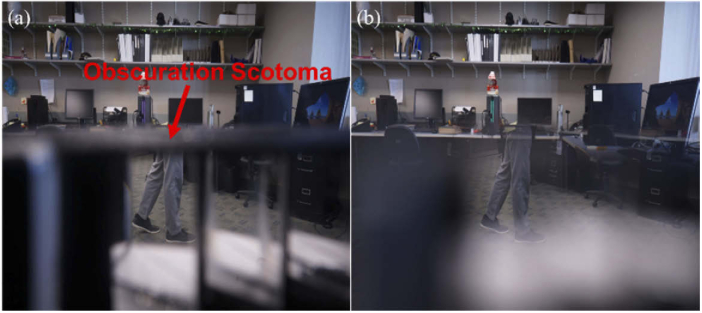
Photographic depiction of views through a lower MPP for left HH to demonstrate the image quality in (a) pinhole-like (f/14) and (b) human-eye-like apertures (f/2.8). A pedestrian approaching from the blind side (left) at a 45° bearing angle would be outside of the camera’s FoV. The MPP brings the pedestrian legs into view in the primary prism with high contrast and no color dispersion. Pinhole like camera (a) shows the narrow vertical obscuration scotomas between the half-penta prisms (Fig. 4) and obscuration scotomas along the upper and lower boundaries of the MPP due to the device protrusion (see discussion). The human-eye-like camera aperture (b) results in softer vignette effects, which reduce the narrower vertical and upper scotomas to a dimmed, and sometimes lower contrast image instead of a complete obscuration. The lens was raised to bring the MPP upper (central) holder almost to the center of the field so as to include the lower (peripheral) holder in the limited FoV of the camera. At this position, the obscuration scotoma (indicated by red arrow) is limited to that created by the holder thickness. The lower obscuration scotomas (not annotated) are much wider and appear as large light grey areas.
3. MPP for field expansion of PFL
3.1. Design of MPP as peripheral prism for PFL
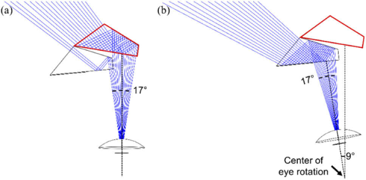
We developed a “see-saw” configuration of peripheral MPPs for PFL (Fig. 10), similar to an earlier design implemented with Fresnel prisms [34,38,53]. Base-out prisms are placed peripherally with the upper segment on one lens and a lower segment on the other lens. The MPP “see-saw” configuration provides 45° field expansion to cover the bearing angle of the highest collision risk. Two 8×4 mm (H×V) half-penta prisms are used in each MPP segment (upper and lower) for a patient with PFL who has a residual central field of 20° diameter. At the primary position of gaze, most of the seeing field is covered by the primary half-penta prism with a couple of degrees expanded through the scanning prism (Fig. 10(a)). When the patient scans into the blind field, the scanning half-penta prism expands the field as shown in Fig. 10(b).
Fig. 10.
Ray tracing (Zemax) of MPP for a patient with PFL of 20° diameter residual central field. The upper segment shown expands the field to the left, using two 8 mm wide half-penta prisms. This design provides 45° shift over a 30° wide FoV in total but due to the patient’s restricted field only about half is visible at any instant. (a) When the patient is in the primary position of gaze a 17° wide section at the top of the residual field [34] is covered mostly by the primary half-penta (red outlined). The rays shown are separated by one degree. (b) With 9° eye scanning to the left, the expansion is provided by the scanning half-penta prism.
Figure 11 illustrates the design of the see-saw MPPs with inter-prism separation of 10° (a little over 3 mm separation on the carrier lenses) and their effects for a patient with PFL of 20° diameter residual central field. The same field expansion effects could be achieved with both MPP segments on one of the lenses with one in a base-out and the other in a base-in configuration. The bilateral design is preferred mostly for cosmetic reasons, as it appears both for the patient and others to be less restrictive. Figure 11(b) illustrates the effects of the system with lateral eye scanning. Within the typical range of lateral saccadic eye movements [26], this design continues to offer, at least some, field expansion. However, on the side opposite to the direction of the eye movement, the field expansion in the corresponding MPP on the fellow eye is largely lost (Fig. 11(b) lower segment). In natural viewing, patients tend to follow an eye movement with a head movement that brings the eye back into the primary position of gaze and thus into the primary effect as shown in Fig. 11(a).
Fig. 11.
Calculated binocular perimetry diagrams with see-saw MPPs for a patient with PFL of a 20° diameter residual central field. (a) At the primary position of gaze, the MPPs shift an area of the scene from 45° eccentricity on both sides, to enable monitoring of the areas of highest collision risk. (b) With a 10° eye scan to the left side, the scene from the upper prism is shifted farther to the left, but the lower prism for rightward expansion is barely usable.
As designed with 10° inter-prism separation, each segment only covers about 5° vertically at the primary position of gaze. With such a short vertical span, a half-penta prism with a shorter height (4 mm ≈ 10°) than used in the MPP configuration for HH would suffice, resulting in a cosmetically better design. The 3D-printed holder positions the two half-penta prisms and is designed to fit into the carrier lens (Fig. 12). Here too the primary prism is placed in front of the carrier lens so that the patient benefits from the refractive correction.
Fig. 12.
CAD design for prototype of MPP for PFL. (a) Showing the upper MPP segment on the left lens with base left. The MPP is mounted at an angle of 5° tilted up to eliminate the obscuration scotoma that would be caused by the bottom surface of the holder (see discussion). The right half-penta prism is the primary element being used in the primary position of gaze. The left half-penta is the eye scanning element. A 3D-printed holder that positions and stabilizes the half-penta prisms is shown as translucent light grey volumes. The right lens (not shown) carries the lower segment with base-right configuration. (b) A magnified view illustrating the details of the lower MPP segment to be mounted in the right carrier lens below the line of sight. This view shows the structure of the wedge and the small protrusions creating the air gaps next to the TIR surfaces.
3.2. Results of MPP for PFL
We prototyped the MPP for PFL design shown in Fig. 9, which cascades two units of 8×4 mm (H×V) half-penta prisms and covers approximately 17° FoV horizontally with 45° field shift (Fig. 13). The prototype has much smaller size and a smaller protrusion than the MPP for HH.
Fig. 13.
Prototype of see-saw peripheral MPPs for PFL. (a) Upper and lower MPPs for PFL. Each includes two half-penta prisms held in a 3D printed black holder, shown from the patient’s view. (b) The MPPs shown mounted into the carrier lenses.
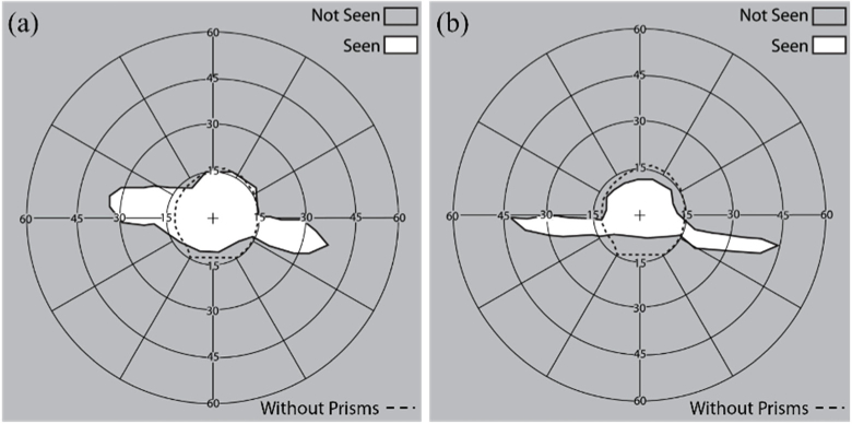
We measured the field expansion of a patient with PFL wearing the see-saw peripheral glasses using both 57Δ Fresnel prism and the MPPs (Fig. 14). The MPPs provided a wider expansion (45°) than the Fresnel prisms (30°).
Fig. 14.
Binocular perimetry results of a patient with PFL using (a) see-saw peripheral Fresnel and (b) MPPs at the primary position of gaze (Fig. 11(a)). Dashed line indicates the visual field extent (∼30° diameter residual central field) without the MPP. (a) 57Δ Fresnel prisms expanded the residual central field up to 35° on either side. (b) MPPs expanded the residual central field up to 45° on either side. Note that the vertical position of the expansion areas is shifted due to vertical head tilt in the perimeter, which does not affect the field recorded without the prisms. Scotomas between the extended visual islands and the residual central field were not measured here.
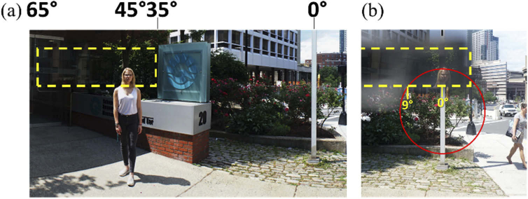
Figure 15 shows the photographic depiction of the effect of an upper segment of a see-saw peripheral MPP for PFL mounted based out (left) in the left carrier lens (only one lens can be mounted in front of the camera at a time). The expected 45° monocular expansion of the FoV is shown.
Fig. 15.
Photographic depiction of view with MPP for PFL. Yellow dashed rectangle indicates the FoV covered by the upper left MPP segment. (a) A panoramic composite image of a street view with a pedestrian located about 45° left from the optical center of the carrier lens (marked by the white lamp post; 0°). (b) The head of the pedestrian at 45° left is visible through the MPP on the left-eye lens within the 20° diameter of the residual central field (marked by the red circle). The field expansion to the right is not shown here, as it is imaged through the right lens with the right eye.
4. Discussion
The novel MPP represents a major improvement in field expansion visual aids for the mobility of patients with HH or PFL. Compared with currently available Fresnel prisms, the nominal shifting power of the MPP is increased by 50% from 30° to 45°. The improvement in image quality is indeed dramatic (Fig. 16). The contrast through the MPP is much higher than through other higher power refractive prisms due to the minimal color dispersion of the mostly reflective MPP. In particular, the contrast through the MPP is much better than through Fresnel prisms, which are more affected by scattering in the non-imaging base than by the color dispersion. The prismatic geometric distortions [45,46], which are disturbing with high power refractive prisms, are not visible in the MPP. With these advantages, we expect the MPPs to gain wide acceptance by the underserved population of patients with field loss.
Fig. 16.
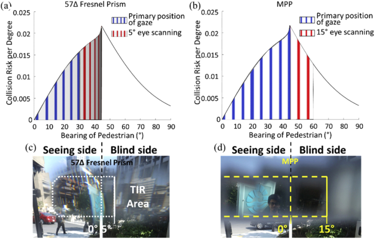
The collision risk with other pedestrians from the blind side for a patient with HH, as a function of bearing angle that can be monitored by the peripheral (a) Fresnel prisms and (b) MPPs. The area under the risk density curve [8] is normalized to 1. The area between any two bearing angles represents the portion of the overall risk monitored within this range by the prism. With the currently used 30° (57Δ) Fresnel prisms, 26% of the potential collisions may be detected in the primary position of gaze (slightly distorted and dimmed blue vertical gratings area), and up to 51% with 5° eye scanning toward the blind side (blue + red areas). Note the expansion by scanning is further limiting detection due to severe minification and dimming of the image illustrated by the minified and dimmed red vertical gratings in (a). (c) Photographic depiction through 57Δ Fresnel prism (the white dotted line) shows a highly distorted/minified image (i.e., the sign with blue logo) and TIR limitation in the prism. With a 45° MPP, the same patient may be able to detect 53% of the potentially colliding pedestrians in the primary position of gaze as illustrated by bright and non-distorted blue gratings (b). The coverage is increased to 79% with farther 15° scanning to the blind side (blue + red areas). Here the higher image quality is illustrated by using bright and non-distorted red gratings in (b). (d) The image through the MPP (yellow dashed line) is not distorted and shows wider field expansion into the blind field (i.e., a man).
An important additional benefit of the MPP over previous peripheral prism devices is the increased range of scanning towards the blind side. As previously discussed [31,32], with high power prisms, when the patient uses eye scanning towards the blind side, additional field expansion possible through the prisms with such movement is highly limited. With the currently used 30° Fresnel prism for HH, no more than 5° of additional expansion is possible because of the limit imposed by the TIR. Because the MPP is mostly a reflective device (there is a small refractive effect) the range to reach TIR is much farther. This enables a full benefit of scanning within the range of common eye movements (up to 15°) [25,26]. This benefit should increase the utility of the device for its main purpose of assisting with the detection of potentially colliding pedestrians. Analyses of the interactions of pedestrian movements in open space environments, such as shopping malls and transportation terminals [8], have shown that the highest risk density for collision is posed by other pedestrians at a bearing angle of 45° (see the peak of the curve in Fig. 16 (a) and (b)). Combining this analysis with the field expansion provided by the conventional Fresnel and MPPs (Figs. 5 and 8, including the effect of eye scanning to the blind side), we compare the proportion of the collision risk that can be monitored (Fig. 16). These analyses demonstrate a substantial increase in utility of the MPP compared with the effects of the conventional Fresnel prism as a pedestrian detection device.
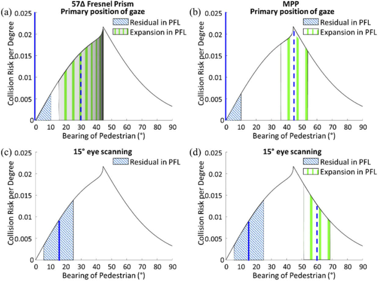
Extending the same analysis to the patient with a 20° diameter of the residual central field, the effect of using the see-saw peripheral prism with the 30° Fresnel prisms is compared with the effect of the 45° MPP in Fig. 17. A patient with PFL cannot detect any potential colliding pedestrians outside the residual central field without the prisms. That patient can monitor and detect potential collisions within the residual field on both sides of fixation.
Fig. 17.
The collision risk with other pedestrians faced by a patient with PFL (20° diameter residual central field), as a function of bearing angle that may be monitored by the peripheral prisms. At the primary position of gaze, the patient with PFL can monitor 10° (half of the residual central field) on each side. Dashed and solid blue vertical lines indicate the foveal projection in and out of the prism, respectively. (a) Using 57Δ peripheral Fresnel prisms that cover horizontally up to 17° of the vertical upper or lower 5° of the residual central field and shifts into that area from an area between 15° and 44° (29°) laterally. The wide 29° shifted FoV is due to strong minification. The severe minification and the dimming of the image (illustrated by the minified and dimmed green vertical gratings in this area) limit the utility of that theoretical wide expansion. (b) The same patient using the 45° MPP is able to monitor the peak of the collision risk bearings and together with the residual central field covers 36% of the risk when in primary position of gaze. Note brighter and undistorted green grating representing the much better quality of the image. With 15° eye scanning, the residual area of central vision (blue hatched area) monitors more risks (6% of the risk). (c) The prism view in the 57Δ Fresnel prism, however, is fully blocked by the TIR, and thus there is no field expansion. (d) The same scanning with the MPP is not blocked by the TIR and the fraction of the risk being monitored is increased to a total of 17%. Note that the risk from the other side, not illustrated in this graph, is not detectable at all with eye scanning into one side.
At the primary position of gaze (Figs. 17(a and b)), the patient can monitor 10° of the residual central field on one side accounting for 3% of the potential collisions (blue hatched area). Since the see-saw peripheral prisms are located 5° above and below the horizontal midline, 17° horizontal FoV out of 20° diameter of the residual central field is covered [34]. Due to the symmetry (same field expansion on both sides), the proportion of the risk being monitored can be calculated and presented on a graph showing only one side. The see-saw Fresnel peripheral prisms increase the coverage to 47%, but the theoretically wide field expansion with the poor image quality and severe minification is not likely to support practical detection of pedestrians. Because of the TIR starting at 5° eccentricity toward the prism base (Fig. 16(c)), only 13° out of 17° horizontal visual field covers the minified shifted view of the blind field from 15° to 44° (29° extent). This minification is non-uniform as it is much stronger closer to the TIR boundary [31]. The transmittance of the shifted view decreases with the minification. Whereas the see-saw Fresnel prism may not provide the calculated field expansion due to these effects, the see-saw MPP presents the full 17° extent of the blind field that covers 45° bearing angle, the peak collision risk, without any image quality limitations (Fig. 17(b)).
With 15° eye scanning to one side, the full 20° diameter of the residual central field covers only the scanning side (blue hatched area in Figs. 17(c and d)) and thus no collision risk in the other side is monitored. In the see-saw Fresnel prisms, the 17° FoV in the scanned eye is still covered by the Fresnel prism, but that does not result in any expansion due to the TIR. Therefore, the coverage with the Fresnel prisms shrinks substantially to 6% (Fig. 17(c)). With the MPP, 15° eye scanning also reduces the monitored risk to 17% mostly due to the loss of the field expansion on the other side. However, the MPP still results in much higher coverage than the Fresnel prisms (Fig. 17(d)). Following the initial eye scan, the head usually turns to re-center the eye at the primary gaze position. Hence, the temporary loss of field expansion on one side may not present a problem.
With lateral eye scanning into either side, the MPP for PFL on the side of the scanning presents the shifted view (left side in Figs. 11(a & b)), but the other prism partially or fully does not contribute to field expansion. This suggests that a better design perhaps might be to provide a third half-penta prism supporting scanning to the apex side, as that will permit continued monitoring of the view on the other side.
We implemented a few prototypes of the MPP for field expansion of HH and for PFL and have demonstrated their efficacy as field expansion devices. The low cost of 3D printing makes these prototypes suitable for further device development and even for clinical studies to evaluate the effectiveness of the devices. These devices are preliminary and additional considerations are needed to refine the designs. Better optical and mechanical designs may improve performance, cosmetics, utility, and maintenance of the devices. For example, even higher powers are possible, as a 60° Bauernfeind prism [42] is available commercially and may be incorporated into cascaded higher power MPP. The placement of MPP also could be reconsidered. Currently, upper and lower MPPs are mounted on the same lens for patients with HH. It may be preferable to mount the lower MPP on the other carrier lens. This will result in trading off scanning range on the bottom for an apical scotoma. Other considerations may take place after clinical testing for device effectiveness, such as designing a system with better cosmetics that is easier to manufacture.
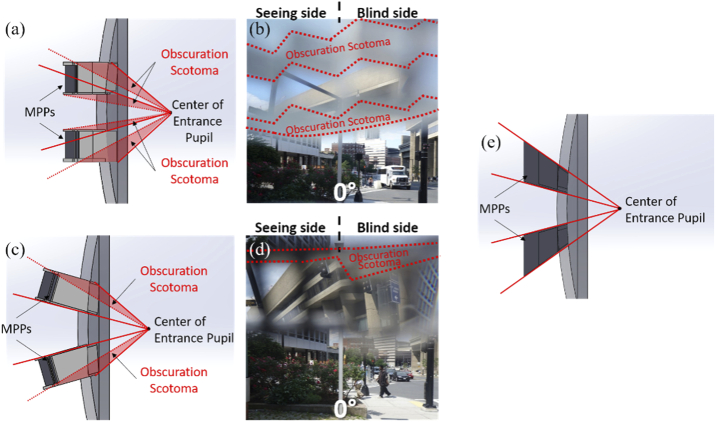
A design change that may be needed even before clinical trials commence is related to the obscuration scotomas (Figs. 9 and 16(d)). The cause of the obscuration scotomas is illustrated schematically in Fig. 18(a) and depicted photographically in Fig. 18(b). These obscurations result in a reduction of the vertical extent of the MPP’s FoV relative to the Fresnel segments best shown in Fig. 14. Using MPPs mounted with a tilt to match the central line of sight as shown in Fig. 18(c), this almost eliminates the central proximal obscuration scotomas and reduces, though does not eliminate the peripheral distal scotomas, as shown in Fig. 18(d). Eliminating the distal obscuration scotomas may be possible by producing a half-penta-like prism specifically designed to match both the central and outside distal line of sight, as shown in Fig. 18(e).
Fig. 18.
Possible improved designs for the peripheral MPP glasses for right HH. (a) Prototype design of peripheral MPP mounting on the carrier lens (side view). (b) Photographic depiction showing just the view through the upper segment. The obscuration scotomas of the upper MPP segment are caused by the central and peripheral holders blocking the lower and upper FoV, respectively, seen as gray blurred areas outlined with red dotted lines. (c) Tilted mounting of the peripheral MPPs designed to eliminate the central obscuration scotoma. (d) Photographic depiction through the upper segment only. It does eliminate the lower obscuration scotoma and reduces the upper scotoma, particularly on the seeing side. This results in a substantially wider vertical span of the view through the MPP. (e) A design of peripheral MPPs following the line of sight both centrally and peripherally using half-penta-like prisms would prevent both the central and peripheral obscuration.
All of the MPP and Fresnel peripheral prism configurations discussed in this paper have been of the horizontal design (i.e. prisms that provide only lateral shifting). One limitation of the horizontal design is that the field expansion does not cover the FoV through a car windshield (which would be located between the upper and lower expansion areas in Fig. 5). However, the oblique design of the peripheral prism [54] provides both vertical and horizontal shifting and thus covers the view through a car windshield [29,54,55]. An oblique upper peripheral prism segment also more effectively detects potentially colliding pedestrians [56]. With the oblique design, the magnitude of the horizontal shift is reduced by trading off to a vertical shift to bring the expansion areas closer to the horizontal midline [32]. The higher power of MPP can provide wider horizontal field expansion even with the vertical shift to close the inter-prism separation. The oblique MPP can be made by cutting obliquely tilted longer MPP (cascaded half-penta prisms). All these new developments and refinements of the MPP device will be continued as future work, and a clinical trial with patients will follow.
Acknowledgements
Ms. Sailaja Manda helped with some of the field diagrams.
Funding
National Eye Institute10.13039/100000053 (R01EY023385, P30EY003790); Massachusetts Technology Transfer Center (MA Acorn Innovation Fund).
Disclosures
Drs. Peli and Vargas-Martin have a patent application for MPP assigned to the Schepens Eye Research Institute and the Universidad de Murcia, Spain.
References
- 1.Yates J. S., Lai S. M., Duncan P. W., Studenski S., “Falls in community-dwelling stroke survivors: An accumulated impairments model,” J. Rehabil. Res. Dev. 39(3), 385–394 (2002). [PubMed] [Google Scholar]
- 2.Bowers A. R., Keeney K., Peli E., “Randomized crossover clinical trial of real and sham peripheral prism glasses for hemianopia,” JAMA Ophthalmol. 132(2), 214–222 (2014). 10.1001/jamaophthalmol.2013.5636 [DOI] [PMC free article] [PubMed] [Google Scholar]
- 3.Chen C. S., Lee A. W., Clarke G., Hayes A., George S., Vincent R., Thompson A., Centrella L., Johnson K., Daly A., Crotty M., “Vision-related quality of life in patients with complete homonymous hemianopia post stroke,” Top. Stroke Rehabil. 16(6), 445–453 (2009). 10.1310/tsr1606-445 [DOI] [PubMed] [Google Scholar]
- 4.Hassan S. E., Hicks J. C., Lei H., Turano K. A., “What is the minimum field of view required for efficient navigation?” Vision Res. 47(16), 2115–2123 (2007). 10.1016/j.visres.2007.03.012 [DOI] [PubMed] [Google Scholar]
- 5.Kuyk T., Elliott J. L., Fuhr P. S., “Visual correlates of obstacle avoidance in adults with low vision,” Optom. Vis. Sci. 75(3), 174–182 (1998). 10.1097/00006324-199803000-00022 [DOI] [PubMed] [Google Scholar]
- 6.Kuyk T., Elliot J. L., Fuhr P. W., “Visual correlates of mobility in real world settings in older adults with low vision,” Optom. Vis. Sci. 75(7), 538–547 (1998). 10.1097/00006324-199807000-00023 [DOI] [PubMed] [Google Scholar]
- 7.Haymes S. A., Johnston A. W., Heyes A. D., “Relationship between vision impairment and ability to perform activities of daily living,” Ophthalmic Physiol. Opt. 22(2), 79–91 (2002). 10.1046/j.1475-1313.2002.00016.x [DOI] [PubMed] [Google Scholar]
- 8.Peli E., Apfelbaum H., Berson E. L., Goldstein R. B., “The risk of pedestrian collisions with peripheral visual field loss,” J. Vis. 16(15), 5 (2016). 10.1167/16.15.5 [DOI] [PMC free article] [PubMed] [Google Scholar]
- 9.Freeman E. E., Munoz B., Rubin G., West S. K., “Visual field loss increases the risk of falls in older adults: The Salisbury Eye Evaluation,” Invest. Ophthalmol. Visual Sci. 48(10), 4445–4450 (2007). 10.1167/iovs.07-0326 [DOI] [PubMed] [Google Scholar]
- 10.Bowers A. R., “Driving with homonymous visual field loss: a review of the literature,” Clin. Exp. Optom. 99(5), 402–418 (2016). 10.1111/cxo.12425 [DOI] [PMC free article] [PubMed] [Google Scholar]
- 11.Papageorgiou E., Hardiess G., Schaeffel F., Wiethoelter H., Karnath H.-O., Mallot H., Schoenfisch B., Schiefer U., “Assessment of vision-related quality of life in patients with homonymous visual field defects,” Graefe's Arch. Clin. Exp. Ophthalmol. 245(12), 1749–1758 (2007). 10.1007/s00417-007-0644-z [DOI] [PubMed] [Google Scholar]
- 12.O’Neill E. C., Connell P. P., O’Connor J. C., Brady J., Reid I., Logan P., “Prism therapy and visual rehabilitation in homonymous visual field loss,” Optom. Vis. Sci. 88(2), 263–268 (2011). 10.1097/OPX.0b013e318205a3b8 [DOI] [PubMed] [Google Scholar]
- 13.Gall C., Lucklum J., Sabel B. A., Franke G. H., “Vision- and health-related quality of life in patients with visual field loss after postchiasmatic lesions,” Invest. Ophthalmol. Visual Sci. 50(6), 2765–2776 (2009). 10.1167/iovs.08-2519 [DOI] [PubMed] [Google Scholar]
- 14.Yanagisawa M., Kato S., Kunimatsu S., Tamura M., Ochiai M., “Relationship between vision-related quality of life in Japanese patients and methods for evaluating visual field,” Jpn. J. Ophthalmol. 55(2), 132–137 (2011). 10.1007/s10384-010-0924-8 [DOI] [PubMed] [Google Scholar]
- 15.Lisboa R., Chun Y. S., Zangwill L. M., Weinreb R. N., Rosen P. N., Liebmann J. M., Girkin C. A., Medeiros F. A., “Association between rates of binocular visual field loss and vision-related quality of life in patients with glaucoma,” JAMA Ophthalmol. 131(4), 486–494 (2013). 10.1001/jamaophthalmol.2013.2602 [DOI] [PMC free article] [PubMed] [Google Scholar]
- 16.Schiller J. S., Lucas J. W., Peregoy J. A., Summary Health Statistics for U.S. Adults: National Health Interview Survey, 2010 Vital Health Stat 10(252) (National Center for Health Statistics, 2012). [PubMed] [Google Scholar]
- 17.Townend B. S., Sturm J. W., Petsoglou C., O’Leary B., Whyte S., Crimmins D., “Perimetric homonymous visual field loss post-stroke,” J. Clin. Neurosci. 14(8), 754–756 (2007). 10.1016/j.jocn.2006.02.022 [DOI] [PubMed] [Google Scholar]
- 18.Rowe F., Brand D., Jackson C. A., Price A., Walker L., Harrison S., Eccleston C., Scott C., Akerman N., Dodridge C., Howard C., Shipman T., Sperring U., MacDiarmid S., Freeman C., “Visual impairment following stroke: do stroke patients require vision assessment?” Age Ageing 38(2), 188–193 (2008). 10.1093/ageing/afn230 [DOI] [PubMed] [Google Scholar]
- 19.Gilhotra J. S., Mitchell P., Healey P. R., Cumming R. G., Currie J., “Homonymous visual field defects and stroke in an older population,” Stroke 33(10), 2417–2420 (2002). 10.1161/01.str.0000037647.10414.d2 [DOI] [PubMed] [Google Scholar]
- 20.Bunker C. H., Berson E. L., Bromley W. C., Hayes R. P., Roderick T. H., “Prevalence of retinitis pigmentosa in Maine,” Am. J. Ophthalmol. 97(3), 357–365 (1984). 10.1016/0002-9394(84)90636-6 [DOI] [PubMed] [Google Scholar]
- 21.Heijl A., Aspberg J., Bengtsson B., “The effect of different criteria on the number of patients blind from open-angle glaucoma,” BMC Ophthalmol. 11(1), 31 (2011). 10.1186/1471-2415-11-31 [DOI] [PMC free article] [PubMed] [Google Scholar]
- 22.Rahman F., Zekite A., Bunce C., Jayaram H., Flanagan D., “Recent trends in vision impairment certifications in England and Wales,” (Available at 10.1038/s41433-020-0864-6 (2020). [DOI] [PMC free article] [PubMed]
- 23.Regan D., Kaushal S., “Monocular discrimination of the direction of motion in depth,” Vision Res. 34(2), 163–177 (1994). 10.1016/0042-6989(94)90329-8 [DOI] [PubMed] [Google Scholar]
- 24.Vargas-Martin F., Peli E., “Eye movement patterns in walking hemianopic patients (abstract),” Invest. Ophthalmol. Vis. Sci. 43, s3809 (2002). [Google Scholar]
- 25.Vargas-Martin F., Peli E., “Eye movements of patients with tunnel vision while walking,” Invest. Ophthalmol. Visual Sci. 47(12), 5295–5302 (2006). 10.1167/iovs.05-1043 [DOI] [PMC free article] [PubMed] [Google Scholar]
- 26.Luo G., Vargas-Martin F., Peli E., “The role of peripheral vision in saccade planning: Learning from people with tunnel vision,” J. Vis. 8(14), 25 (2008). 10.1167/8.14.25 [DOI] [PMC free article] [PubMed] [Google Scholar]
- 27.Gameiro R. R., Junemann K., Herbik A., Wolff A., Konig P., Hoffmann M. B., “Natural visual behavior in individuals with peripheral visual-field loss,” J. Vis. 18(12), 10 (2018). 10.1167/18.12.10 [DOI] [PubMed] [Google Scholar]
- 28.Peli E., “Field expansion for homonymous hemianopia by optically-induced peripheral exotropia,” Optom. Vis. Sci. 77(9), 453–464 (2000). 10.1097/00006324-200009000-00006 [DOI] [PubMed] [Google Scholar]
- 29.Houston K. E., Peli E., Goldstein R. B., Bowers A. R., “Driving with hemianopia VI: Peripheral prisms and perceptual-motor training improve blind-side detection in a driving simulator,” Transl. Vis. Sci. Technol. 7(1), 5 (2018). 10.1167/tvst.7.1.5 [DOI] [PMC free article] [PubMed] [Google Scholar]
- 30.Apfelbaum H. L., Ross N. C., Bowers A. R., Peli E., “Considering apical scotomas, confusion, and diplopia when prescribing prisms for homonymous hemianopia,” Transl. Vis. Sci. Technol. 2(4), 2 (2013). 10.1167/tvst.2.4.2 [DOI] [PMC free article] [PubMed] [Google Scholar]
- 31.Jung J.-H., Peli E., “Impact of high power and angle of incidence on prism corrections for visual field loss,” Opt. Eng. 53(6), 061707 (2014). 10.1117/1.OE.53.6.061707 [DOI] [PMC free article] [PubMed] [Google Scholar]
- 32.Peli E., Bowers A. R., Keeney K., Jung J.-H., “High-power prismatic devices for oblique peripheral prisms,” Optom. Vis. Sci. 93(5), 521–533 (2016). 10.1097/OPX.0000000000000820 [DOI] [PMC free article] [PubMed] [Google Scholar]
- 33.Apfelbaum H., Peli E., “Tunnel vision prismatic field expansion: Challenges and requirements,” Transl. Vis. Sci. Technol. 4(6), 8 (2015). 10.1167/tvst.4.6.8 [DOI] [PMC free article] [PubMed] [Google Scholar]
- 34.Qiu C., Jung J.-H., Tuccar-Burak M., Spano L. P., Goldstein R. B., Peli E., “Measuring the effects of prisms on pedestrian collision detection with peripheral field loss,” Transl. Vis. Sci. Technol. 7(5), 1 (2018). 10.1167/tvst.7.5.1 [DOI] [PMC free article] [PubMed] [Google Scholar]
- 35.Alberti C., Goldstein R. B., Peli E., Bowers A. R., “Driving with hemianopia V: Do individuals with hemianopia spontaneously adapt their gaze scanning to differing hazard detection demands?” Transl. Vis. Sci. Technol. 6(5), 11 (2017). 10.1167/tvst.6.5.11 [DOI] [PMC free article] [PubMed] [Google Scholar]
- 36.Alberti C. F., Peli E., Bowers A. R., “Driving with hemianopia: III. Detection of stationary and approaching pedestrians in a simulator,” Invest. Ophthalmol. Visual Sci. 55(1), 368–374 (2014). 10.1167/iovs.13-12737 [DOI] [PMC free article] [PubMed] [Google Scholar]
- 37.Bowers A. R., Alberti C. A., Houston K., Goldstein R. B., Peli E., “Gaze scanning and intersection detection failures by drivers with hemianopia (abstract),” Invest. Ophthalmol. Vis. Sci. 56(7), E-abstract 4778 (2015).26218905 [Google Scholar]
- 38.Peli E., Jung J.-H., “Multiplexing prisms for field expansion,” Optom. Vis. Sci. 94(8), 817–829 (2017). 10.1097/OPX.0000000000001102 [DOI] [PMC free article] [PubMed] [Google Scholar]
- 39.Jung J.-H., Peli E., “No useful field expansion with full-field prisms,” Optom. Vis. Sci. 95(9), 805–813 (2018). 10.1097/OPX.0000000000001271 [DOI] [PMC free article] [PubMed] [Google Scholar]
- 40.Choi H. J., Peli E., Park M., Jung J.-H., “Design of 45° periscopic visual field expansion device for peripheral field loss,” Opt. Commun. 454, 124364 (2020). 10.1016/j.optcom.2019.124364 [DOI] [PMC free article] [PubMed] [Google Scholar]
- 41.Peli E., Vargas-Martin F., “Expansion of field of view,” Intl. patent (2019).
- 42.Yoder P. R., Mounting Optics in Optical Instruments, second (SPIE Press, 2008), Vol. PM181. [Google Scholar]
- 43.MIL-HDBK-141 , “Military Standardization Handbook, Optical Design.,” 16-18 of section 14 (Defense Supply Agency, Washington 25, D.C., 1962). [Google Scholar]
- 44.Greivenkamp J. E., Field Guide to Geometrical Optics (SPIE Press, 2004). [Google Scholar]
- 45.Ogle K., “Distortion of the image by prisms,” J. Opt. Soc. Am. 41(12), 1023–1028 (1951). 10.1364/JOSA.41.001023 [DOI] [Google Scholar]
- 46.Ogle K., “Distortion of the Image by Ophthalmic Prisms,” Arch. Ophthalmol. 47(2), 121–131 (1952). 10.1001/archopht.1952.01700030126001 [DOI] [PubMed] [Google Scholar]
- 47.Katz M., “Visual acuity through Fresnel, refractive, and hybrid diffractive/refractive prisms,” Optometry 75(8), 503–508 (2004). 10.1016/S1529-1839(04)70175-X [DOI] [PubMed] [Google Scholar]
- 48.Katz M., “Contrast sensitivity through hybrid diffractive, Fresnel, and refractive prisms,” Optometry 75(8), 509–516 (2004). 10.1016/S1529-1839(04)70176-1 [DOI] [PubMed] [Google Scholar]
- 49.Fannin T. E., Grosvenor T., “The Correction of Ametropia,” in Clinical Optics, 2nd ed. (Butterworth-Heinemann, 1996), pp. 109–126. [Google Scholar]
- 50.Jung J.-H., Peli E., “Field expansion for acquired monocular vision using a multiplexing prism,” Optom. Vis. Sci. 95(9), 814–828 (2018). 10.1097/OPX.0000000000001277 [DOI] [PMC free article] [PubMed] [Google Scholar]
- 51.Satgunam P., Apfelbaum H. L., Peli E., “Volume perimetry: measurement in depth of visual field loss,” Optom. Vis. Sci. 89(9), E1265–E1275 (2012). 10.1097/OPX.0b013e3182678df8 [DOI] [PMC free article] [PubMed] [Google Scholar]
- 52.Jung J.-H., Peli E., Kurukuti N. M., “Photographic Depiction of the effects of visual aids on field of view,” Optom. Vis. Sci. 96, E-abstract 190018 (2018). [DOI] [PMC free article] [PubMed] [Google Scholar]
- 53.Peli E., “Vision modification based on a multiplexing prism,” US patent 10,031,346 B2 (Jul. 24, 2018).
- 54.Peli E., “Peripheral field expansion device,” United States patent US 7,374,284 B2 (May 20, 2008, 2008).
- 55.Bowers A. R., Tant M., Peli E., “A pilot evaluation of on-road detection performance by drivers with hemianopia using oblique peripheral prisms,” Stroke Res. Treat. 2012, 176806 (2012). 10.1155/2012/176806 [DOI] [PMC free article] [PubMed] [Google Scholar]
- 56.Kurukuti N. M., Tang K., Jung J.-H., Peli E., “Effect of peripheral prism configurations on pedestrian collision detection while walking (Abstract),” Invest. Ophthalmol. Vis. Sci. 61, 2771 (2020). [Google Scholar]


