Abstract
We report herein the first visible light optical coherence tomography angiography (vis-OCTA) for human retinal imaging. Compared to the existing vis-OCT systems, we devised a spectrometer with a narrower bandwidth to increase the spectral power density for OCTA imaging, while retaining the major spectral contrast in the blood. We achieved a 100 kHz A-line rate, the fastest acquisition speed reported so far for human retinal vis-OCT. We rigorously optimized the imaging protocol such that a single acquisition took < 6 seconds with a field of view (FOV) of 3×7.8 mm2. The angiography enables accurate localization of microvasculature down to the capillary level and thus enables oximetry at vessels < 100 µm in diameter. We demonstrated microvascular hemoglobin oxygen saturation (sO2) at the feeding and draining vessels at the perifoveal region. The longitudinal repeatability was assessed by < 5% coefficient of variation (CV). The unique capabilities of our vis-OCTA system may allow studies on the role of microvascular oxygen in various retinal pathologies.
1. Introduction
Visible light optical coherence tomography (vis-OCT) [1–11] is a new derivation of OCT that uses visible light illumination instead of a conventional near-infrared (NIR) light [12]. One advantage of vis-OCT is its spatio-spectral analysis within the microvasculature for label-free oximetry (i.e. measuring hemoglobin oxygen saturation, sO2) [4,13–20]. Compared to 2D hyperspectral imaging modalities [21,22], vis-OCT’s precise 3D localization of blood vessels excludes a myriad of confounding factors from other tissue depths, enabling accurate and reliable oximetry measurements.
The first demonstration of vis-OCT dated back to 2002 [23], but the first in vivo vis-OCT retinal imaging was not reported until 2011 [24]. On the other hand, the development of vis-OCT oximetry has made significant progress during the past 10 years. The feasibility of using visible light for oximetry was first demonstrated in vitro in 2010 [25,26], and in vivo in 2011 [6]. Subsequently, the first demonstration of vis-OCT retinal oximetry was reported in 2013 in rat retinas, showing the sO2 calculations in the major arterioles and venules immediately exiting and entering the optic nerve head (ONH) [4]. When combined with the Doppler OCT measurements of blood flow, the oxygen metabolic rate from the inner retinal circulation could be quantified to access the global inner retinal functions and study the dynamic interaction between the retinal and choroidal circulations [3,15,27,28]. Later, human retinal imaging by vis-OCT was demonstrated in 2015 [29] and human retinal oximetry by vis-OCT was reported in 2017 [13,17] .
So far, most reports on vis-OCT human retinal oximetry describe vessels in close proximity with the ONH with vessel diameters above 100 µm [13,17] . The arteriovenous difference in those major vessels provides a global assessment of inner retinal metabolic activity but is less informative for localized metabolic alterations. For example, primary open-angle glaucoma (POAG) frequently manifests with visual field defects in the early stage only at the peripheral retina, gradually progressing towards the central visual field while diabetic retinopathy and macular degeneration often impact the foveal region initially. Therefore, measurement of localized inner retina metabolic change with focal oximetry in smaller vessels, even down to the capillary level, is highly desirable for better disease characterization.
Therefore, our overall motivation is to perform human retinal oximetry in retinal vessels less than100 µm in diameter by vis-OCT angiography (vis-OCTA). The paper consists of two major components. First, we implemented vis-OCTA in human retina to aid 3D localization of small vessels and capillaries. Given the sensitivity of our system, we optimized the scanning protocol to achieve a 3×7.8 mm2 field of view (FOV). Second, we performed microvascular oximetry at the macular region, focusing on individual arterioles and venules immediately above the capillary network and then the capillary network itself after spatial averaging. The measured oximetry values were validated based on the known alternating pattern of feeding arterioles and draining venules in the macula. The sO2 from the capillary network was found to be intermediate between measured values of the arterioles and venules.
2. Methods
2.1. System
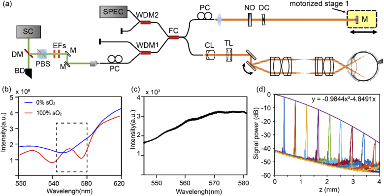
The vis-OCT system was modified from our previous visible and near infrared OCT setup, with only the visible light channel operating (Fig. 1(a)) [7]. Two edge filters selected the illumination wavelength range from 545 to 580 nm (Fig. 1(b), 1(c)). We intentionally used a narrower bandwidth than our previous design to increase the power spectral density for subsequent vis-OCTA processing. Within the bandwidth, the large spectral contrast between oxy- and deoxy-blood can still be captured (Fig. 1(b)). The sample arm consisted of a fiber collimator (f = 7.5 mm), a pair of galvanometer mirrors (GVS002, Thorlabs, USA), and a 2:1 telescope relay system. We also installed an electronically tunable lens (EL-3-10, Optotune AG, Switzerland) for a fast-focusing adjustment. We used a custom-made spectrometer to record the spectral interferograms. The spectrometer consisted of a fiber collimator (f = 60 mm), a 2400 lines/mm transmission diffraction grating (Wasatch Photonics, USA), a focusing lens (f = 150 mm), and a high-speed line scan camera (E2 V Octoplus, Teledyne, France). The laser power on the pupil was less than 0.25 mW, and the A-line speed was 100 kHz with an exposure time of 9.7 µs for each A-line. We note that Chong et. al., and Zhang et. al. used 0.15 and 0.08 mW power at the cornea, respectively, but for vis-OCT structural human retinal imaging [17,30]. We characterized the roll-off performance of the system using a mirror reflectance as the sample, and an ND filter (OD=2) to attenuate the sample signal (Fig. 1(d)). The sensitivity was estimated to be ∼82 dB and the roll-off speed was ∼6 dB/mm in air. The axial resolution was measured to be ∼5 µm close to the zero-delay line.
Fig. 1.
The system characteristics. (a) Schematic of the vis-OCTA system. SC: supercontinuum source; DM: dichroic mirror; BD: beam dump; PBS: polarization beam splitter; EF: edge filter; M: mirror; PC: polarization controller; WDM: wavelength division and multiplexer; FC: fiber coupler; CL: collimating lens; TL: tunable lens; ND: neutral density filter; DC: dispersion controller. (b) The wavelength selection of the spectrometer. Simulated scattering signal from the oxygenated and deoxygenated blood. (c) The measured light source spectrum. (d) System roll-off characterization.
All the experimental procedures were approved by the Boston Medical Center Institutional Review Board and adhered to the tenets of the Declaration of Helsinki. Informed consent was obtained prior to imaging.
2.2. Vis-OCTA imaging and processing
The scanning protocol is conventional and modified from our previous paper [31]. The fast scanning galvanometer mirror was controlled by an 80% duty cycle sawtooth wave. The slow scanning was controlled by a ramping wave. At each slow scanning location, repetitive frames were taken to harness the motion contrast of blood flow for vis-OCTA. There are three essential parameters in the imaging protocol: numbers of repetitive frames (Nrep), the time interval between two adjacent frames (ΔT) for the motion contrast, and the A-line scanning density on the retina (ΣAline, µm-1). These three parameters altogether determine the vis-OCTA image quality and the FOV, and their optimization is discussed in the Results section.
The method to generate wavelength-dependent four-dimensional (x, y, z, λ) vis-OCTA and vis-OCT has been described before [27,32]. We combined the split-spectrum OCTA and the complex-signal-based optical microangiography to enhance the motion contrast [33,34]. The split-spectrum method also provides the spectral information for sO2 calculation.
The original raw spectrograms were pre-processed by normalizing the source spectrum, a DC removal, k-space resampling, and a digital dispersion compensation for improving the image sharpness [35]. A Gaussian spectral window in the wavenumber k domain (FWHM k = 0.11 µm-1) was then used to sweep the whole interferogram in 11 steps to generate the wavelength-dependent complex OCT signal after a series of Fourier transforms. The differential contrast between two adjacent frames at one slow scanning location was taken based on the complex OCT signal, and then the absolute value was taken as the OCTA signal. When Nrep is larger than 2, all the OCTA signals from two adjacent B-scans were averaged to assemble an OCTA frame.
| (1) |
where C(x, z, λi) is the complex B-scan image at each spectral window λi. After vis-OCTA were generated for each Gaussian spectral window, we averaged them to compile one 3D vis-OCTA image.
For wavelength-dependent vis-OCT structural images, we simply average the absolute values of Nrep frames at each B-scan location, instead of taking differential contrast as in OCTA:
| (2) |
2.3. Data processing for oximetry in small vessels
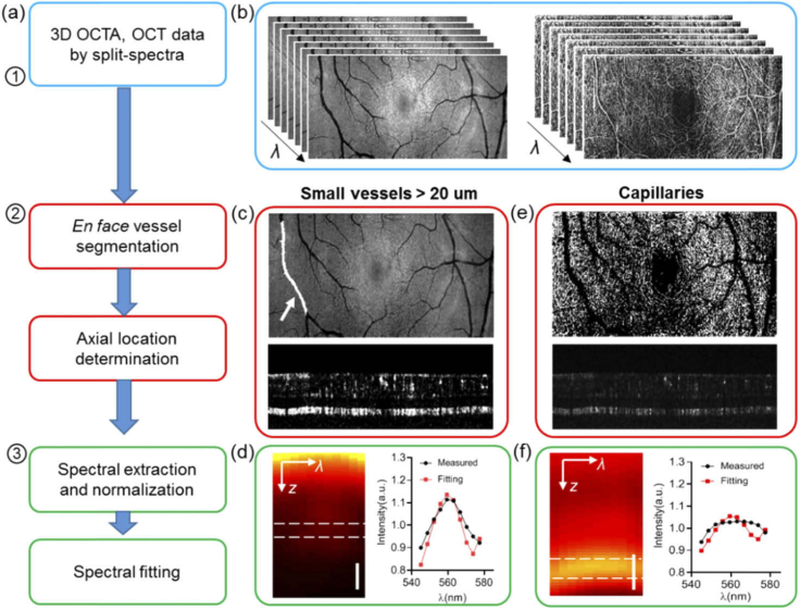
We used the following workflow to extract the microvascular spectral signal and calculate the sO2 (Fig. 2(a)). The first step is to generate wavelength-dependent vis-OCT and vis-OCTA four dimensional (x, y, z, λi) datasets (Fig. 2(b)), as described above. The second step is to locate the blood vessels through en face and axial segmentations. The third step is spectral normalization and extraction to estimate sO2.
Fig. 2.
Data processing flow for small vessel and capillary sO2 calculation. (a) Flow chart of the data processing. (b) Wavelength-dependent vis-OCT and vis-OCTA generated by a split spectra method. (c) Illustration of the vessel segmentation on the lateral projection image from vis-OCT, and vessel bottom selection on vis-OCTA for small vessels > 20 µm. (d) An example of the averaged spectrograph in terms of depth within a vessel, and the spectrum extracted from the vessel bottom for the spectral fitting (red). (e) Illustration of capillary segmentation from en face vis-OCTA projection and the depth locations. (f) An example of a spectrogram on capillaries, and the spectrum extracted from the spectral fitting.
2.3.1. Vessel segmentation
For individual arterioles and venules, the en face maximum intensity projection (MIP) of vis-OCT was used to locate the lateral region of interest (ROI) for the vessels. The vessel ROI was manually segmented and stored as the vessel mask (Fig. 2(c)). We detected the retinal surface by setting an intensity threshold from the structural vis-OCT B-scans. The same surface was used in both vis-OCT and vis-OCTA datasets. We then flattened the retina surface and located the vessel bottom by the lower boundary of the vis-OCTA signal within each vessel segment (Fig. 2(c)). For each vessel segment, a constant depth selection was used for the spectral extraction assuming a consistent vessel size.
The capillary flow signal from the en face MIP of vis-OCTA was used to isolate the capillary network. The larger vessels were marked out as shown in Fig. 2(e). Then we binarized the image to serve as the capillary ROI. To locate the depth of the capillaries, the axial position of the maximum value along each vis-OCTA A-line within the capillary ROI was recorded.
2.3.2. Spectral extraction and normalization
After 3D segmentation, a spectrogram in terms of depth was generated. We emphasize that the spectrogram was extracted from vis-OCT structural data instead of angiographic data. Vis-OCTA is only used to locate the vessels in 3D. The processing for arterioles and venules, and capillaries are described separately as below.
2.3.2.1. Arterioles and venules
For individual arterioles and venules, the vessel surface was flattened and all vis-OCT A-lines within the vessel lateral ROI were averaged to generate a spectrogram in z and λ (Fig. 2(d)). Then the spectrum was obtained by averaging signals from a depth range of 10 µm centered at the vessel bottom. To remove systemic bias due to propagation through the eye, we further performed a spectral normalization by the spectrum from the non-vascular nerve fiber layer tissues [17,36].
2.3.2.2. Capillaries
For capillaries, we flattened all the capillaries and averaged the signal within the capillary lateral ROI to generate the spectrogram in z and λ as shown in Fig. 2(f). The signals from a depth range of 10 µm centered on the capillaries were averaged to extract the spectrum, which was further normalized by the spectrum averaged from the inner plexiform layer and the inner nuclear layer excluding the capillaries.
2.3.3. Spectral fitting to estimate sO2
After the spectra were extracted and normalized, we used a previously published method to calculate sO2 by matching the experimental spectra with the following model [4,27]:
| (3) |
in which I0(λ) is the spectrum of the light source; R0 is the reflectance of the reference arm and assumed to be a constant. r(λ) (dimensionless) is the reflectance at the vessel wall, modelled by a power law r(λ) = Aλ-α, with A being a dimensionless constant and α modelling the decaying scattering spectrum from the vessel wall. The optical attenuation coefficient µ (mm−1) combines the absorption (µa) and scattering coefficients (µs) of the whole blood, which is both wavelength- and sO2-dependent:
| (4) |
where W is a scaling factor for the scattering coefficient at W = 0.2 [4,25]. Hb and HbO2 denote the contribution from the deoxygenated and oxygenated blood, respectively. z denotes the light-penetration length through vessels. When taking a logarithmic operation, Equ. 3 turns to a linear equation to µ,
| (5) |
Then a least square fitting was performed to match experimental spectrum I(λ) and model-based spectra to estimate sO2 by optimizing a vector x,
| (6) |
so that sO2 is calculated by sO2=x3/(x3+x4); and x1 = ½ log(A), x2 = ½ α, x3 = sO2×z, x4 = (1-sO2)×z according to Eq. (5). The common variable z is removed by taking the ratio. We used the nonnegative linear least-squares fitting function lsqnonneg in Matlab. The values of sO2 and α are reported in the result section. We should note that because of the additional spectral normalization by the retinal tissue, x1 is found to be zero for all our spectral fittings, and the physical definition for α in Eq. (5) may not hold.
3. Results
3.1. Imaging protocol optimization
We first evaluated the effect of Nrep on vis-OCTA’s signal-to-noise ratio (SNR), defined by
| (7) |
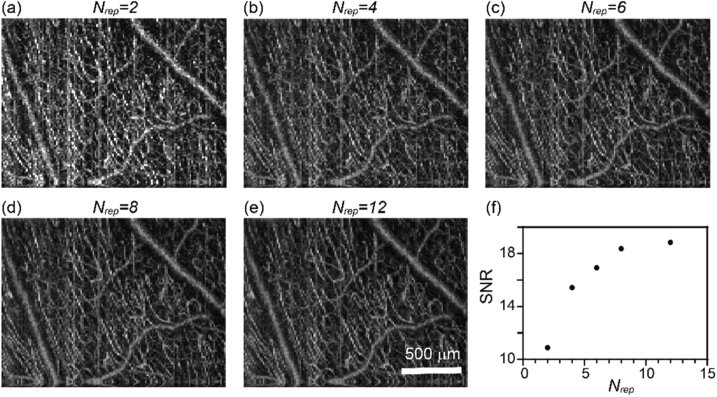
where Iv is the vis-OCTA intensity on blood vessels, and SDnv is the image intensity standard deviation within the background non-vascular areas [37]. We collected a dataset by Nrep = 12, and processed vis-OCTA images from the first Nrep frames for Nrep = 2, 4, 6, 8, 12. For example, the case of Nrep = 2 only processed the first two frames and so on. This approach ensures that the other experimental conditions are virtually identical. We can see the image quality improvement when averaging more vis-OCTA frames (Fig. 3(a)–3(e)). The image SNR increases more rapidly at the beginning and slows down when Nrep > 6 (Fig. 3(f)). While the image quality improves with increasing Nrep, the acquisition time proportionally increases as well. Therefore, we chose Nrep = 3 for the final imaging protocol to balance the image SNR and the total scanning time. The image density in Fig. 3 is 320 by 128 pixels.
Fig. 3.
The effect of Nrep on human retina vis-OCTA. (a-e) En face maximum intensity projection of vis-OCTA in the inner retina at Nrep equal to 2-12 at each B-scan location. (f) Capillary vis-OCTA SNR versus Nrep.
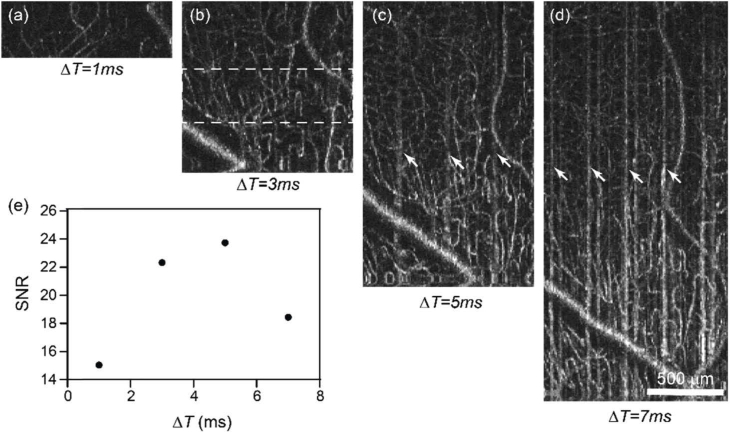
We next evaluated the effect of ΔT on the image quality. The A-line scanning density was kept constant at 0.13 µm-1, while increasing ΔT from 1 ms to 7 ms by increasing the number of A-lines per frames from 80 to 560. As a result, the length in the fast scanning direction increased as well (Fig. 4(a)–4(d)) from 0.6 to 4.3 mm, respectively. The same FOV was imaged in all cases in Fig. 4(a), so that the SNR calculation could be repeated at the same imaging location. We noticed that the image contrast changes non-monotonically, increasing until ΔT = 5 ms and decreasing at ΔT = 7 ms. The initial SNR increase may be due to the larger decorrelation between two repeated frames when ΔT increases. The contrast then deteriorates when ΔT becomes longer than 5 ms as clear motion artifacts start to appear (e.g. vertical stripes in Fig. 4(c), 4(d)). To balance the FOV and the image quality, we chose ΔT = 5 ms for our imaging protocol. At 100 kHz A-line rate and 80% duty cycle of the fast scanning, ΔT = 5 ms determines the number of A-line per B-scan in our protocol to be 400, resulting in a ∼3 mm scanning range in fast axis.
Fig. 4.
The effect of the B-scan interval time on human retina vis-OCTA. (a-d) En face maximum intensity projection of vis-OCTA in the inner retina at the interval time ΔT equal to 1-7 ms between two consecutive frames at each B-scan location, while the A-scan density were maintained constant. White arrows points to motion artefacts. (e) Capillary vis-OCTA SNR versus ΔT.
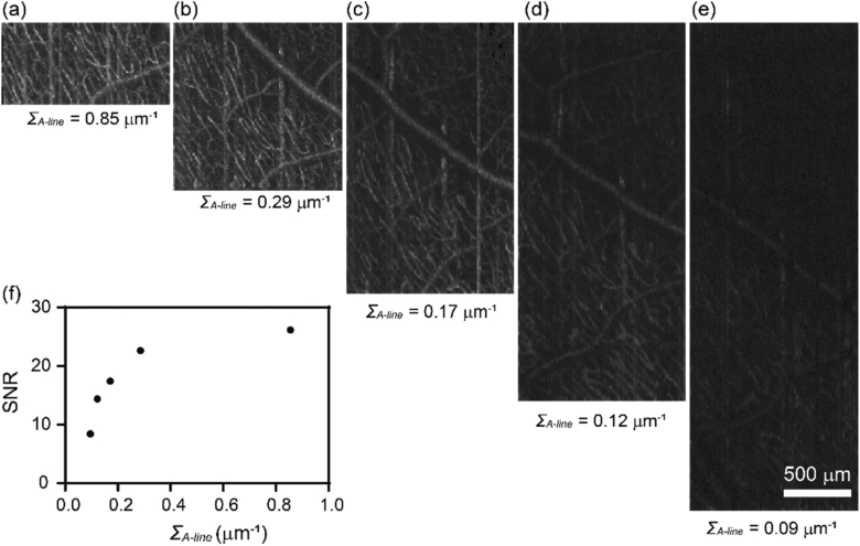
Lastly, we evaluated the effect of A-line scanning density on the vis-OCTA SNR. We kept Nrep and ΔT constant at Nrep = 3 and ΔT = 4 ms with 320 A-line per B-scan. The length of the scanning was controlled by the amplitude of the sawtooth wave fed to the fast scanning galvanometer mirror. Based on the scanning angle at the pupil entrance and the approximated eyeball diameter of ∼25 mm, we varied the scanning length from approximately 0.375 to 3.375 mm in five acquisitions, corresponding to the A-line scanning density ΣA-line = 0.85, 0.29, 0.17, 0.12 and 0.09 µm-1. As Fig. 5 shows, the image SNR decreases with the decreased A-line scanning density. This effect is likely due to the fringe washout effect as each exposure integrate signals from the scanning length per pixel and becomes more prominent as the scanning length increases. To balance the FOV, image quality and acquisition time, we chose ΣA-line = 0.13 µm-1, ΔT = 5 ms, and 400 A-lines per frame for the final imaging protocol, which yielded an imaging length on the fast scanning direction of ∼ 3 mm.
Fig. 5.
The effect of the A-line scanning density within a B-scan on human retina vis-OCTA. (a-e) En face maximum intensity projection of vis-OCTA in the inner retina at the A-line scanning density ΣA-line equal to 0.85-0.09 µm within a B-scan, while Nrep and ΔT were maintained constant. (f) Capillary vis-OCTA SNR versus ΣA-line.
3.2. Human retina vis-OCTA
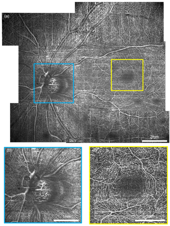
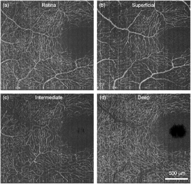
After optimizing the protocol, we performed vis-OCTA on a human volunteer as shown in Fig. 6.The FOV at one single acquisition took 400 × 400 pixels to cover ∼3×7.8 mm in the retina. The Nrep = 3 and the total time for one acquisition was 6 s. Figure 6(a) shows a wide field vis-OCTA mosaic including 11 acquisitions. Detailed microvasculature down to individual capillary-level can be visualized in two magnified images (Fig. 6(b),(c)). After the split-spectra processing, the depth resolution was relaxed to ∼27 µm, sufficient to isolate the superficial, intermediate, and deep capillary plexuses at the macula (see appendix, Fig. 8). The capillary contrast is higher within the nerve fiber arcade, which is consistent with the high metabolic demand in the retinal nerve fiber layer and the ganglion cells.
Fig. 6.
Human retina vis-OCTA. (a) A mosaic wide-field vis-OCTA en face projection made of 10 acquisitions on a healthy volunteer aged 37. (b-c) The magnified details of the capillary networks at the optic nerve head and fovea.
3.3. Microvascular sO2 in human retina in vivo
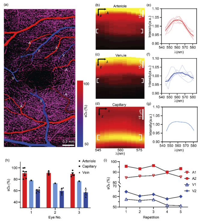
We performed vis-OCT microvascular oximetry at the foveal region as demonstrated in Fig. 7. We color-coded the vis-OCTA images with sO2 values for small vessel segments and the whole capillary bed (Fig. 7(a)). The alternating pattern of feeding arterioles and draining venules is apparent around fovea as demonstrated by the sO2 estimations. As expected, the averaged sO2 value over the capillary bed is intermediate between the values of the arterioles and venules. We plotted a representative spectrogram from an arterial segment, a venule segment, and the underlying capillary networks (Fig. 7(b)–7(d)). Figures 7(b) and 7(c) both have higher intensity at the vessel surface and this intensity attenuates when penetrating through the vessels. The depth at the vessel bottom provides sufficient signal contrast to extract reliable spectra. Figure 7(d) exhibits a different pattern with the strongest signal appearing within the capillaries as expected based on the stronger capillary contrast in structural vis-OCT images [30,38] .
Fig. 7.
Human retinal oximetry on small vessels and capillaries by vis-OCTA. (a) Color-coded by sO2 on arterioles, venules and capillaries at the perifoveal region. (b-d) Representative spectrogram from an arteriole, a venule and the capillary network from panel (a). (e-f) The measured spectra from all arterioles and venules, and capillary network. The solid and light curves were the mean and individual spectra from all the vessels in panel (a). The capillary spectrum was averaged within the entire FOV as shown in panel (a). (h) sO2 calculations from three healthy eyes. Bar = Mean ± SEM. (i) The longitudinal repeatability from different vessels from the same healthy eye.
In Fig. 7(e)–7(g), the spectra from all the arterioles, venules, and capillary beds displayed in Fig. 7(a) are plotted. The spectral contrast of the blood resembles that seen with the oxygenated blood plotted in Fig. 1(b), showing a peak around 560 nm. The value of sO2 estimation is then plotted in Fig. 7 h as the 1st subject. We further performed the same method on two additional healthy eyes, and their results are also summarized in the same graph, and Table 1. Overall, the mean values of arterial, venous, and capillary sO2 are quite consistent among three different subjects.
Table 1. Summary of microvascular sO2 measurements at the perifoveal region from three healthy eyes.
| Eye 1 | Eye 2 | Eye 3 | All | |
|---|---|---|---|---|
| No. # | ||||
| Arterioles | 7 | 3 | 4 | 14 |
| Venules | 6 | 4 | 3 | 13 |
| Diameter (µm) | ||||
| Arterioles | 48.4 ± 8.0 | 85.4 ± 4.3 | 55.6 ± 10.4 | 58.4 ± 6.1 |
| Venules | 53.5 ± 12.2 | 61.6 ± 6.0 | 52.0 ± 8.8 | 55.7 ± 5.6 |
| sO2 (%) | ||||
| Arterioles | 90.7 ± 3.0 | 90.9 ± 2.0 | 89.4 ± 2.4 | 90.4 ± 1.64 |
| Venules | 60.6 ± 1.4 | 59.7 ± 3.0 | 56.9 ± 4.5 | 59.5 ± 1.4 |
| Capillary | 77.99 | 72.95 | 76.6 | 75.8 ± 1.5 |
| α | ||||
| Arterioles | 0.70 ± 0.40 | 0.38 ± 0.30 | 1.04 ± 0.58 | 0.72 ± 0.26 |
| Venules | 2.58 ± 1.66 | 3.48 ± 1.98 | 4.66 ± 1.22 | 3.34 ± 1.04 |
| Capillary | 0 | 0 | 0 | 0 |
We also tested the repeatability of the microvascular sO2 by vis-OCTA (Fig. 7(i),). A total of 5 measurements were taken from the same eye on three different dates (see appendix, Table 2). The first three repetitions were taken on the same day, and the other two were taken on different days spanning over 5 weeks. The coefficients of variation (CV) for all measured vessels are < 3% within the same day and < 5% over all the repetitions.
4. Discussion
In this paper, we describe the first vis-OCTA imaging of human retina using a redesigned spectrometer and optimized imaging protocol allowing for enhanced vascular signal and localization of the microvasculature. Using our methods, we are capable of measuring sO2 in vessels with diameter smaller than 100 µm, all the way down to the capillary networks. We demonstrate the robustness and repeatability of sO2 calculation. The unprecedented significance of our vis-OCTA oximetry is the capability of excluding confounding factors from other retinal layers through 3D segmentation. In addition, the accurate vessel localization of vis-OCTA allows for measurement of capillary sO2, which is unattainable by fundus-based oximetry.
One limitation of this study is the lack of independent validation of our sO2 calculation. In our previous studies on rodent retinal oximetry, a pulse oximetry was used to serve as a gold standard for arterial sO2 close to the ONH [27,32]. sO2 alterations due to oxygen diffusion as blood travels through the retina would limit this approach for validation of measurements in microvasculature distant from the ONH. From our calculations, we observe the clear separation of alternating feeding arterioles and draining venules, which serves as a physiologic and anatomic validation. Yet we still lack a gold standard for capillary sO2. Further physiologic (e.g. hypoxia challenge) or pathologic validations with known impact on oxygen levels are warranted to rigorously validate the accuracy and sensitivity of microvascular sO2 by vis-OCTA.
We should also emphasize that all the spectral extraction was performed on structural vis-OCT signals, with vis-OCTA provided vessel localization. Because of the stringent requirements for imaging speed and SNR for vis-OCTA, the FOV was limited to 3×7.8 mm2 at each acquisition with 6s total acquisition time at the current system characterization. This may be a limiting factor for large-scale clinical applications. Alternatively, we could use a dual-channel system with both visible and conventional near infrared (NIR) wavelengths to simultaneously acquire OCTA images [7,24]. While the NIR channel could provide rapid OCTA with a larger FOV for vessel localization, the co-registered vis-OCT structural data could provide spectral contrast for sO2.
To summarize, we have for the first time demonstrated vis-OCTA human retinal imaging. By achieving a 100 kHz A-line rate, the fastest acquisition speed reported so far for human retinal vis-OCT, we can acquire a single human retinal imaging data with a FOV of 3×7.8 mm2 within 6 seconds. The angiography also enables accurate localization of microvasculature to allow us to perform human retinal oximetry in vessels less than100 µm in diameter. This technical advance lays a foundation for assessing human retinal local oxygen extraction and metabolism.
Appendix
Fig. 8.
(a) Human retinal capillaries at macula by vis-OCTA. (b-d) The superficial, intermediate, and deep capillary plexus isolated from (a).
Table 2. The repeatability of the microvascular sO2 (%).
| Arteriole 1 | Arteriole 2 | Venule 1 | Venule 2 | |
|---|---|---|---|---|
| Day 0 | 95.58 | 84.7 | 64.58 | 57.37 |
| Day 0 | 93.18 | 86.11 | 60.45 | 56.2 |
| Day 0 | 96.25 | 86.68 | 61.99 | 57.12 |
| Day 2 | 90.16 | 89.2 | 57.69 | 51.76 |
| Day 37 | 93.39 | 85.4 | 60.02 | 51.28 |
Funding
Bright Focus Foundation (G2017077, M2018132); National Institutes of Health10.13039/100000002 (R01CA232015, R01NS108464-01, R21EY029412).
Disclosures
The authors declare no conflicts of interest.
References
- 1.Shu X., Beckmann L. J., Zhang H. F., “Visible-light optical coherence tomography: a review,” J. Biomed. Opt. 22(12), 1 (2017). 10.1117/1.JBO.22.12.121707 [DOI] [PMC free article] [PubMed] [Google Scholar]
- 2.Ju M. J., Huang C., Wahl D. J., Jian Y., Sarunic M. V., “Visible light sensorless adaptive optics for retinal structure and fluorescence imaging,” Opt. Lett. 43(20), 5162–5165 (2018). 10.1364/OL.43.005162 [DOI] [PubMed] [Google Scholar]
- 3.Pi S., Camino A., Wei X., Simonett J., Cepurna W., Huang D., Morrison J. C., Jia Y., “Rodent retinal circulation organization and oxygen metabolism revealed by visible-light optical coherence tomography,” Biomed. Opt. Express 9(11), 5851–5862 (2018). 10.1364/BOE.9.005851 [DOI] [PMC free article] [PubMed] [Google Scholar]
- 4.Yi J., Wei Q., Liu W., Backman V., Zhang H. F., “Visible-light optical coherence tomography for retinal oximetry,” Opt. Lett. 38(11), 1796–1798 (2013). 10.1364/OL.38.001796 [DOI] [PMC free article] [PubMed] [Google Scholar]
- 5.Merkle C. W., Chong S. P., Kho A. M., Zhu J., Dubra A., Srinivasan V. J., “Visible light optical coherence microscopy of the brain with isotropic femtoliter resolution in vivo,” Opt. Lett. 43(2), 198–201 (2018). 10.1364/OL.43.000198 [DOI] [PMC free article] [PubMed] [Google Scholar]
- 6.Robles F. E., Wilson C., Grant G., Wax A., “Molecular imaging true-colour spectroscopic optical coherence tomography,” Nat. Photonics 5(12), 744–747 (2011). 10.1038/nphoton.2011.257 [DOI] [PMC free article] [PubMed] [Google Scholar]
- 7.Song W., Zhou L., Zhang S., Ness S., Desai M., Yi J., “Fiber-based visible and near infrared optical coherence tomography (vnOCT) enables quantitative elastic light scattering spectroscopy in human retina,” Biomed. Opt. Express 9(7), 3464–3480 (2018). 10.1364/BOE.9.003464 [DOI] [PMC free article] [PubMed] [Google Scholar]
- 8.Coquoz S., Marchand P. J., Bouwens A., Mouchiroud L., Sorrentino V., Szlag D., Auwerx J., Lasser T., “Label-free three-dimensional imaging of Caenorhabditis elegans with visible optical coherence microscopy,” PLoS One 12(7), e0181676 (2017). 10.1371/journal.pone.0181676 [DOI] [PMC free article] [PubMed] [Google Scholar]
- 9.Marchand P. J., Szlag D., Bouwens A., Lasser T., “In vivo high-resolution cortical imaging with extended-focus optical coherence microscopy in the visible-NIR wavelength range,” J. Biomed. Opt. 23(03), 1 (2018). 10.1117/1.JBO.23.3.036012 [DOI] [PubMed] [Google Scholar]
- 10.Lichtenegger A., Harper D. J., Augustin M., Eugui P., Muck M., Gesperger J., Hitzenberger C. K., Woehrer A., Baumann B., “Spectroscopic imaging with spectral domain visible light optical coherence microscopy in Alzheimer’s disease brain samples,” Biomed. Opt. Express 8(9), 4007–4025 (2017). 10.1364/BOE.8.004007 [DOI] [PMC free article] [PubMed] [Google Scholar]
- 11.Veenstra C., Petersen W., Vellekoop I. M., Steenbergen W., Bosschaart N., “Spatially confined quantification of bilirubin concentrations by spectroscopic visible-light optical coherence tomography,” Biomed. Opt. Express 9(8), 3581–3589 (2018). 10.1364/BOE.9.003581 [DOI] [PMC free article] [PubMed] [Google Scholar]
- 12.Huang D., Swanson E. A., Lin C. P., Schuman J. S., Stinson W. G., Chang W., Hee M. R., Flotte T., Gregory K., Puliafito C. A., Fujimoto J. G., “Optical Coherence Tomography,” Science 254(5035), 1178–1181 (1991). 10.1126/science.1957169 [DOI] [PMC free article] [PubMed] [Google Scholar]
- 13.Chen S., Shu X., Nesper P. L., Liu W., Fawzi A. A., Zhang H. F., “Retinal oximetry in humans using visible-light optical coherence tomography [Invited],” Biomed. Opt. Express 8(3), 1415–1429 (2017). 10.1364/BOE.8.001415 [DOI] [PMC free article] [PubMed] [Google Scholar]
- 14.Chong S. P., Merkle C. W., Leahy C., Srinivasan V. J., “Cerebral metabolic rate of oxygen (CMRO2) assessed by combined Doppler and spectroscopic OCT,” Biomed. Opt. Express 6(10), 3941–3951 (2015). 10.1364/BOE.6.003941 [DOI] [PMC free article] [PubMed] [Google Scholar]
- 15.Pi S., Hormel T. T., Wei X., Cepurna W., Camino A., Guo Y., Huang D., Morrison J. C., Jia Y., “Monitoring retinal responses to acute intraocular pressure elevation in rats with visible light optical coherence tomography,” Neurophotonics 6(04), 1 (2019). 10.1117/1.NPh.6.4.041104 [DOI] [PMC free article] [PubMed] [Google Scholar]
- 16.Liu R., Winkelmann J. A., Spicer G., Zhu Y., Eid A., Ameer G. A., Backman V., Yi J., “Single capillary oximetry and tissue ultrastructural sensing by dual-band dual-scan inverse spectroscopic optical coherence tomography,” Light: Sci. Appl. 7(1), 1–13 (2018). 10.1038/s41377-018-0007-z [DOI] [PMC free article] [PubMed] [Google Scholar]
- 17.Chong S. P., Bernucci M., Radhakrishnan H., Srinivasan V. J., “Structural and functional human retinal imaging with a fiber-based visible light OCT ophthalmoscope,” Biomed. Opt. Express 8(1), 323–337 (2017). 10.1364/BOE.8.000323 [DOI] [PMC free article] [PubMed] [Google Scholar]
- 18.Liu R., Cheng S., Tian L., Yi J., “Deep spectral learning for label-free optical imaging oximetry with uncertainty quantification,” Light: Sci. Appl. 8(1), 1–13 (2019). 10.1038/s41377-018-0109-7 [DOI] [PMC free article] [PubMed] [Google Scholar]
- 19.Veenstra C., Kruitwagen S., Groener D., Petersen W., Steenbergen W., Bosschaart N., “Quantification of total haemoglobin concentrations in human whole blood by spectroscopic visible-light optical coherence tomography,” Sci. Rep. 9(1), 15115–8 (2019). 10.1038/s41598-019-51721-9 [DOI] [PMC free article] [PubMed] [Google Scholar]
- 20.Pi S., Hormel T. T., Wei X., Cepurna W., Wang B., Morrison J. C., Jia Y., “Retinal capillary oximetry with visible light optical coherence tomography,” Proc. Natl. Acad. Sci. U. S. A. 117(21), 11658–11666 (2020). 10.1073/pnas.1918546117 [DOI] [PMC free article] [PubMed] [Google Scholar]
- 21.Kristjansdottir J. V., Hardarson S. H., Stefansson E., “Retinal Oximetry with a Scanning Laser Ophthalmoscope compared to a Fundus Camera Oximeter,” Invest. Ophthalmol. Visual Sci. 55(5), 3120–3204 (2014). 10.1167/iovs.13-13255 [DOI] [PubMed] [Google Scholar]
- 22.Palsson O., Geirsdottir A., Hardarson S. H., Olafsdottir O. B., Kristjansdottir J. V., Stefánsson E., “Retinal Oximetry Images Must Be Standardized: A Methodological Analysis,” Invest. Ophthalmol. Visual Sci. 53(4), 1729–1733 (2012). 10.1167/iovs.11-8621 [DOI] [PubMed] [Google Scholar]
- 23.Povazay B., Apolonski A. A., Unterhuber A., Hermann B., Bizheva K. K., Sattmann H., Russell P. S. J., Krausz F., Fercher A. F., Drexler W., “Visible light optical coherence tomography,” in Coherence Domain Optical Methods in Biomedical Science and Clinical Applications VI (International Society for Optics and Photonics, 2002), Vol. 4619, pp. 90–94. [Google Scholar]
- 24.Zhang X., Hu J., Knighton R. W., Huang X.-R., Puliafito C. A., Jiao S., “Dual-band spectral-domain optical coherence tomography for in vivo imaging the spectral contrasts of the retinal nerve fiber layer,” Opt. Express 19(20), 19653–19659 (2011). 10.1364/OE.19.019653 [DOI] [PMC free article] [PubMed] [Google Scholar]
- 25.Yi J., Li X., “Estimation of oxygen saturation from erythrocytes by high-resolution spectroscopic optical coherence tomography,” Opt. Lett. 35(12), 2094–2096 (2010). 10.1364/OL.35.002094 [DOI] [PubMed] [Google Scholar]
- 26.Robles F. E., Chowdhury S., Wax A., “Assessing hemoglobin concentration using spectroscopic optical coherence tomography for feasibility of tissue diagnostics,” Biomed. Opt. Express 1, 310–317 (2010). 10.1364/BOE.1.000310 [DOI] [PMC free article] [PubMed] [Google Scholar]
- 27.Yi J., Liu W., Chen S., Backman V., Sheibani N., Sorenson C. M., Fawzi A. A., Linsenmeier R. A., Zhang H. F., “Visible light optical coherence tomography measures retinal oxygen metabolic response to systemic oxygenation,” Light: Sci. Appl. 4(9), e334 (2015). 10.1038/lsa.2015.107 [DOI] [PMC free article] [PubMed] [Google Scholar]
- 28.Song W., Fu S., Song S., Zhang S., Zhang L., Ness S., Desai M., Yi J., “Longitudinal detection of retinal alterations by visible and near-infrared optical coherence tomography in a dexamethasone-induced ocular hypertension mouse model,” Neuphotonics 6, 041103 (2019). 10.1117/1.NPh.6.4.041103 [DOI] [PMC free article] [PubMed] [Google Scholar]
- 29.Yi J., Chen S., Shu X., Fawzi A. A., Zhang H. F., “Human retinal imaging using visible-light optical coherence tomography guided by scanning laser ophthalmoscopy,” Biomed. Opt. Express 6(10), 3701–3713 (2015). 10.1364/BOE.6.003701 [DOI] [PMC free article] [PubMed] [Google Scholar]
- 30.Zhang T., Kho A. M., Srinivasan V. J., “Improving visible light OCT of the human retina with rapid spectral shaping and axial tracking,” Biomed. Opt. Express 10(6), 2918–2931 (2019). 10.1364/BOE.10.002918 [DOI] [PMC free article] [PubMed] [Google Scholar]
- 31.Song W., Zhou L., Kot K. L., Fan H., Han J., Yi J., “Measurement of flow-mediated dilation of mouse femoral artery in vivo by optical coherence tomography,” J. Biophotonics 11(11), e201800053 (2018). 10.1002/jbio.201800053 [DOI] [PMC free article] [PubMed] [Google Scholar]
- 32.Yi J., Chen S., Backman V., Zhang H. F., “In vivo functional microangiography by visible-light optical coherence tomography,” Biomed. Opt. Express 5(10), 3603–3612 (2014). 10.1364/BOE.5.003603 [DOI] [PMC free article] [PubMed] [Google Scholar]
- 33.Jia Y., Tan O., Tokayer J., Potsaid B., Wang Y., Liu J. J., Kraus M. F., Subhash H., Fujimoto J. G., Hornegger J., Huang D., “Split-spectrum amplitude-decorrelation angiography with optical coherence tomography,” Opt. Express 20(4), 4710–4725 (2012). 10.1364/OE.20.004710 [DOI] [PMC free article] [PubMed] [Google Scholar]
- 34.Chen C.-L., Wang R. K., “Optical coherence tomography based angiography [Invited],” Biomed. Opt. Express 8(2), 1056–1082 (2017). 10.1364/BOE.8.001056 [DOI] [PMC free article] [PubMed] [Google Scholar]
- 35.Wojtkowski M., Srinivasan V. J., Ko T. H., Fujimoto J. G., Kowalczyk A., Duker J. S., “Ultrahigh-resolution, high-speed, Fourier domain optical coherence tomography and methods for dispersion compensation,” Opt. Express 12(11), 2404–2422 (2004). 10.1364/OPEX.12.002404 [DOI] [PubMed] [Google Scholar]
- 36.Chong S. P., Merkle C. W., Leahy C., Radhakrishnan H., Srinivasan V. J., “Quantitative microvascular hemoglobin mapping using visible light spectroscopic Optical Coherence Tomography,” Biomed. Opt. Express 6(4), 1429–1450 (2015). 10.1364/BOE.6.001429 [DOI] [PMC free article] [PubMed] [Google Scholar]
- 37.Wang R. K., Zhang A., Choi W. J., Zhang Q., Chen C., Miller A., Gregori G., Rosenfeld P. J., “Wide-field optical coherence tomography angiography enabled by two repeated measurements of B-scans,” Opt. Lett. 41(10), 2330–2333 (2016). 10.1364/OL.41.002330 [DOI] [PMC free article] [PubMed] [Google Scholar]
- 38.Pi S., Hormel T. T., Wei X., Cepurna W., Morrison J. C., Jia Y., “Imaging retinal structures at cellular-level resolution by visible-light optical coherence tomography,” Opt. Lett. 45(7), 2107–2110 (2020). 10.1364/OL.386454 [DOI] [PMC free article] [PubMed] [Google Scholar]


