Abstract
We develop a mixed formulation for incompressible hyper-elastodynamics based on a continuum modeling framework recently developed in [41] and smooth generalizations of the Taylor-Hood element based on non-uniform rational B-splines (NURBS). This continuum formulation draws a link between computational fluid dynamics and computational solid dynamics. This link inspires an energy stability estimate for the spatial discretization, which favorably distinguishes the formulation from the conventional mixed formulations for finite elasticity. The inf-sup condition is utilized to provide a bound for the pressure field. The generalized-α method is applied for temporal discretization, and a nested block preconditioner is invoked for the solution procedure [42]. The inf-sup stability for different pairs of NURBS elements is elucidated through numerical assessment. The convergence rate of the proposed formulation with various combinations of mixed elements is examined by the manufactured solution method. The numerical scheme is also examined under compressive and tensile loads for isotropic and anisotropic hyperelastic materials. Finally, a suite of dynamic problems is numerically studied to corroborate the stability and conservation properties.
Keywords: Incompressible elasticity, Mixed formulation, Inf-sup condition, Energy stability, Generalized-α method, Anisotropic arterial wall model
1. Introduction
1.1. Motivation and literature survey
Over the past few decades, significant progress has been achieved in the finite element modeling of solid mechanics problems. A central topic is to devise a numerical scheme that works well in the incompressible limit. Under the small-strain assumption, this issue is well-understood, and it boils down to interpolating the displacement and pressure with elements that satisfy the Ladyzhenskaya-Babuška-Brezzi (LBB) or the inf-sup condition [4]. Under large strains, most materials exhibit volume-preserving behavior, which makes it imperative to appropriately handle the incompressibility constraint. In fact, the nonlinear nature of large strain analysis, together with the kinematic constraint, makes the numerical analysis of incompressible materials quite challenging. Classical treatments of this class of problems include the -projection method [10, 12, 28], the enhanced assumed strain method (EAS) [53, 51], and the mixed u/p formulation [55].
The -projection and EAS methods share some similarities. Both methods are developed based on the multiplicative split of the deformation gradient; the geometrically linear versions of the two methods are linked with the mixed finite element method [4, 23]. Nevertheless, there are drawbacks of both. For the -projection method, its assembly routine requires a nonlocal matrix inversion if the projection is onto a continuous finite element space. For example, when using the higher-order NURBS within the -projection method, one needs to invert a “mass” matrix defined over a patch of elements to obtain the projection in each call of the element assembly routine [12, Appendix C]. In our opinion, this makes its implementation quite complex and unappealing. It has long been known that the EAS method suffers from mesh instability or the hourglass mode [56] and hence necessitate further refinements to numerical technologies for the hourglass control. The penalty nature of the pure displacement formulation inevitably induces an ill-conditioned stiffness matrix, which imposes a severe constraint on the choice of linear solvers.
The mixed u/p formulation introduces a pressure-like variable as the Lagrange multiplier for the incompressibility constraint in the strain energy [55]. The resulting scheme necessitates interpolating the displacement and pressure fields independently. Performing a linearization of this formulation provides a justification for the use of inf-sup stable elements [3]. Yet, for nonlinear problems, linearized stability is often insufficient to guarantee nonlinear stability [20]. It remains unclear whether there is any a priori nonlinear stability estimate for the mixed u/p formulation.
In the meantime, the stabilized finite element method, as a technique initially developed for computational fluid dynamics, has been extended to solid mechanics based on various variational formulations [1, 6, 34, 41, 45, 49, 58]. Using the stabilized formulation allows one to interpolate physical quantities with equal-order interpolations. This feature gives practitioners maximum flexibility in mesh generation and numerical implementation, and allows for low-order elements which are more robust than their higher-order counterparts. Equal-order interpolations always give an optimal constraint ratio [24, Chapter 4], which may be regarded as another appealing feature for incompressible elasticity. The stabilization term can be interpreted as a subgrid scale model within the variational multiscale framework [25, 27, 41, 45]. The design of the subgrid scale model involves tunable parameters and relies on numerical experiences. Oftentimes, the choice of the subgrid scale model has a crucial impact on the solution quality. Readers are referred to [58] for a discussion on the design of the subgrid scale model for inelastic calculations. This issue partly motivates this work, in which we aim to design a stable numerical formulation for incompressible hyperelasticity that does not rely on subgrid scale numerical models with tunable parameters.
1.2. Overview of the proposed method
It is well-known that a finite element scheme is based on the formulation (i.e., the variational principle) and the discrete function spaces (i.e., the elements). Both components need to be properly accounted for in the design of numerical schemes. In this work, we introduce a mixed variational formulation different from the existing mixed u/p formulation [55]. In the classical formulation, the momentum balance equations are coupled with an algebraic equation of state, which relates the pressure with J, the determinant of the deformation gradient [21, Chapter 8]. In the incompressible limit, this relation reduces to J = 1. In the new mixed formulation, the momentum equations are coupled with the differential mass equation written in terms of the pressure primitive variable set. The volumetric behavior is reflected through the so-called isothermal compressibility factor [41]. In the incompressible limit, this term approaches zero, and the mass equation degenerates to the divergence-free constraint for the velocity field. Although J = 1 is equivalent to the divergence-free constraint for the velocity field at the continuum level, they lead to different schemes at the discrete level. Based on the new mixed formulation, an a priori energy stability estimate can be obtained, and the inf-sup condition leads to a bound for the pressure solution. We regard these estimates as critical numerical properties embedded in the formulation that guarantee reliable results.
It should be pointed out that there are some existing formulations [19, 30, 43] that bear some similarity to ours, the key difference being that the Cauchy stress was expressed in a rate form in prior formulations. It is known that the rate constitutive equations are not built from free energies and cannot account for reversible elastic behavior [52]. Therefore, prior formulations cannot have an a priori energy stability estimate. Additionally, the rate constitutive equation requires special numerical considerations [29]. We aim to address these issues through the proposed formulation.
The choice of elements plays an equally critical role in numerical design for large-strain elasticity problems. Here, we attempt to provide a numerical technique that can be conveniently and robustly extended to the higher-order regime. The NURBS elements have been shown to enjoy superior robustness for large strain analysis [9, 37]. We adopt the same set of NURBS basis functions for the description of the geometry and approximation of the displacement field, aligning the proposed numerical formulation with the paradigm of isogeometric analysis [26]. The unique concept of k-refinement in isogeometric analysis allows one to generate higher-continuity basis functions without proliferation of degrees of freedom. In contrast, the p-refinement strategy elevates the polynomial degree without changing the continuity, and it leads to an inhomogeneous proliferated nodal structure. However, it should be pointed out that in the setting of mixed finite elements, although the k-refinement leads to a pair of velocity-pressure elements that enjoy nearly the optimal constraint ratio [24, Chapter 4], it has been observed that such element types are not always inf-sup stable [46]. To remedy this issue, it has been proposed to use subdivision technology to generate a NURBS analogue for the Q1-iso-Q2 element [11, 32, 46]. In this work, we adopt an alternative approach, the inf-sup stable smooth generalizations of the Taylor-Hood element. In our opinion, the Taylor-Hood element is more convenient for implementation, especially in the parallel setting. We numerically assess the inf-sup stability for different combinations of the p- and k-refinements for generating the Taylor-Hood elements. It will be observed that the elements pass the numerical test if the polynomial degree is elevated at least once by the p-refinement to generate the discrete velocity space. Using the above new mixed formulation and the stable smooth generalizations of the Taylor-Hood element offer a new approach for incompressible large strain elastodynamics with several appealing features: it is well-behaved in the incompressible regime, the semi-discrete formulation respects energy stability, it does not involve tunable parameters or subgrid scale numerical models, it can achieve improved accuracy, especially for stress calculations, by employing higher-order smooth basis functions.
The remainder of the work is organized as follows. In Section 2, we state the governing equations and weak formulation for hyper-elastodynamics. In Section 3, the numerical scheme is presented and its numerical properties are analyzed. Following that, we numerically assess the inf-sup stability of different pairs of mixed NURBS elements. The elements that pass the test are used in the simulations for benchmark problems in Section 4. We draw conclusions in Section 5.
2. Hyper-elastodynamics
2.1. The initial boundary-value problem
Let ΩX and be bounded open sets in with Lipschitz boundaries, wherein d represents the number of spatial dimensions. The motion of the body is described by a family of smooth mappings parameterized by the time coordinate t,
In the above, x represents the current position of a material particle originally located at X, which implies φ(X,0) = X. The displacement and velocity of the material particle are defined as
In this work, we use d(·)/dt to denote a total time derivative. The spatial velocity is defined as . Analogously, we define . The deformation gradient, the Jacobian determinant, and the right Cauchy-Green tensor are defined as
We define and as
which represent the distortional parts of F and C. We denote the thermodynamic pressure of the continuum body as p and the density as ρ. The mechanical behavior of an elastic material can be described by a Gibbs free energy . It is shown in [41] that the Gibbs free energy can be additively split into an isochoric part and a volumetric part,
The constitutive relations for the density ρ, the isothermal compressibility factor βθ, and the deviatoric part of the Cauchy stress can be described in terms of the Gibbs free energy as follows,
wherein the projector and the fictitious second Piola-Kirchhoff stress are defined as
is the fourth-order identity tensor, and ρ0 is the density in the referential configuration. Interested readers are referred to [41] for a detailed discussion of the governing equations and the constitutive relations. It is known that ρJ = ρ0 due to mass conservation in the Lagrangian description. We can therefore introduce ρ(J) = ρ0/J as an alternative way of defining the density in the Lagrangian framework. In fact, we will adopt this choice in the following discussion. Under the isothermal condition, the energy equation is decoupled, and it suffices to consider the following equations for the motion of the continuum body,
| (1) |
| (2) |
| (3) |
In the above system, the equation (1) describes the kinematic relation, and the equations (2) and (3) describe the conservation of mass and the balance of linear momentum. The boundary can be partitioned into two non-overlapping subdivisions: , wherein is the Dirichlet part of the boundary, and is the Neumann part of the boundary. Boundary conditions can be stated as
| (4) |
Given the initial data u0, p0, and v0, the initial conditions can be stated as
| (5) |
The equations (1)–(5) constitute an initial-boundary value problem for elastodynamics.
Remark 1.
It is known that J = 1 is equivalent to ∇x·v = 0 due to the identity dJ/dt = J∇x·v. However, the usage of ∇x·· v = 0, or more generally the equation (2), is less frequent to see in the classical solid mechanics community with few exceptions [15, 49]. A reason is that the constraint J = 1 is fitted into the elastostatic model, and the usage of v inevitably necessitates an elastodynamic model, which needs additional considerations in the numerical formulation. Another reason could be the missing link between βθ and the strain energy. The constitutive relation for βθ allows compressible materials and is recently derived in [41].
Remark 2.
It is worth pointing out that there is a different variational formulation recently developed [5, 6, 15]. It contains an additional set of kinematic relations for F, JF −T, and J. For polyconvex constitutive models, one is able to symmetrize the formulation and obtain an interesting connection of it with the entropy variable concept.
Since the above system looks different from the existing theory for hyperelasticity, we give an example of the constitutive model here. Let I1 and I2 designate the first and second invariants of the right Cauchy-Green tensor, that is,
For isotropic materials, the isochoric part of the free energy can be conveniently expressed in terms of and . The Mooney-Rivlin model can be expressed as
where c1 and c2 are parameters that have the same dimension as pressure. The volumetric part of the Gibbs free energy can be built as a Legendre transformation of the Helmholtz volumetric free energy [41]. Here, we give an example
| (6) |
which is transformed from the energy proposed in [38]. In (6), κ designates the bulk modulus. This free energy leads to the relation
As the bulk modulus κ approaches infinity, the material becomes incompressible, and we have Gvol(p) = p/ρ0 in the limit. This volumetric energy leads to ρ(p) = ρ0 and βθ(p) = 0.
2.2. Reduction to the small-strain theory
Assuming the strain is infinitesimally small, we have ∇x = ∇X and ρ(J) = ρ0. We also assume that Gvol adopts the form given in (6). Then the mass equation (2) can be written as
| (7) |
Integrating the above relation in time results in
| (8) |
with a proper choice of the reference value for the pressure. Assuming further that the we are seeking a static equilibrium solution, the momentum equation (3) becomes
| (9) |
The equations (8)–(9) constitute the classical mixed formulation for the small strain elastostatics [24, Chapter 4].
Remark 3.
For elastodynamics, one may instinctively add an inertial term to (9) and couple it with (8). However, numerical simulations indicate that this system is probably ill-posed. It is suggested to couple (9) with (7) rather than (8) for dynamic calculations [49]. A potential mathematical explanation is that (8) does not provide the proper coercive structure in the dynamic setting. This point will be further clarified in Proposition 1.
2.3. Weak formulation
Henceforth, we restrict our discussion to fully incompressible materials. Let us denote the trial solution spaces for the displacement, velocity, and pressure in the current domain as , , and , respectively. The Dirichlet boundary condition defined on is properly built into the definitions of the and . Let and denote the corresponding test function spaces. The mixed formulation on the current configuration can be stated as follows. Find such that for t ∈ [0, T],
| (10) |
| (11) |
| (12) |
for , with y(0) = {u0,p0,v0}T. Here u0, p0, and v0 are the projections of the initial data onto the trial solution spaces. It is worth pointing out that although the material is fully incompressible, we still use ρ(J) = ρ0/J in (12), since the resulting discrete scheme cannot guarantee pointwise satisfaction of J = 1. In the above and henceforth, the formulations for the kinematic equations, the mass equation, and the linear momentum equations are indicated by the superscripts k, p and m, respectively. The equations (10)–(12) constitute the weak form of the problem. Performing integration by parts and using the localization argument, one can show the equivalence between the weak-form problem and the initial-boundary value problem. Let us define the following quantities on the material frame of reference via a pull-back operator:
Correspondingly, the trial solution spaces are denoted as , and ; the test function spaces are denoted as and . The weak formulation can be alternatively stated as follows. Find such that for t ∈ [0, T],
| (13) |
| (14) |
| (15) |
for , with Y (0) = {U0,P0,V0}T. Here U0, P0, and V0 are the projections of the initial data onto the spaces , , and respectively.
3. Numerical formulation
In this section, we discuss the numerical procedures for the solution of the incompressible hyper-elastodynamics based on the weak formulation given in Section 2.3.
3.1. Spline spaces on the parametric domain
We start by reviewing the construction of B-splines and NURBS basis functions. Given the polynomial degree p and the dimensionality of the B-spline space n, the knot vector can be represented by Ξ := {ξ1, ⋯·,ξn+p+1}, wherein 0 = ξ1 ≤ ξ2 ≤ ⋯ ≤ ξn+p+1 = 1. With the knot vector, the B-spline basis functions of degree p, denoted as for i = 1,·⋯, n, can be defined recursively. The definition starts with the case of p = 0, in which the basis functions are defined as piecewise constants,
For p ≥ 1, the basis functions are defined through the Cox-de Boor recursion formula,
The NURBS basis functions of degree p are defined by the B-spline basis functions and a weight vector {w1, ⋯, wn} as
If we ignore the repetitive knots, the knot vector can be defined by a vector {ζ1,·⋯·, ζm} representing the distinctive knots and a vector {r1,·⋯·, rm} recording the corresponding knot multiplicities. In this work, we consider open knot vectors, meaning r1 = rm = p + 1. We further assume that ri ≤ p for i = 2,·⋯, m − 1. At the point ζi, the B-spline basis functions have αi := p − ri continuous derivatives. The vector
is referred to as the regularity vector. We adopt the notation When αi takes the value −1, the basis functions are discontinuous at ζi. The spaces and are defined as
The notations and are used to indicate that αi = α for i = 2,⋯, m − 1, meaning the spline function spaces have continuity Cα. The construction of multivariate B-spline and NURBS basis functions follows a tensor-product manner. Consider a unit cube , which is referred to as the parametric domain. Given pl, nl for l = 1,·⋯, d, we denote the knot vectors as Ξl = {ξ1,l,·⋯·, ξnl+pl+1,l}. Associated with each knot vector, the univariate B-spline basis functions for il = 1,·⋯, nl are defined. Consequently, the tensor-product B-spline basis functions can be defined as
Given the weight vectors {w1,l, ⋯,wn,l} for l = 1,·⋯,d, the univariate NURBS basis functions are defined. Correspondingly, the multivariate NURBS basis functions are defined as
The tensor product NURBS space is denoted as
3.2. Semi-discrete formulation and a priori estimates
In this work, we always consider three-dimensional problems (i.e. d = 3). Two discrete function spaces and can be defined on as
where 1 ≤ a and 0 ≤ b ≤ a are integers. We assume that the referential configuration of the body can be exactly parametrized by a geometrical mapping . The discrete functions on the referential domain are defined through the pull-back operators,
This pair of elements can be viewed as a generalization of the Taylor-Hood element [22], where the polynomial degree and the continuity can achieve arbitrarily high order. With the discrete function spaces and defined, we define the trial solution spaces for the displacement, pressure, and velocity on the referential configuration as
Given the displacement , one may obtain φh = Uh(X,t) + X. Consequently, the trial solution spaces for the displacement, pressure, and velocity on the current configuration can be defined as
and the test function spaces are defined as
The semi-discrete formulation can be stated as follows. Find such that for t ∈ [0,T],
| (16) |
| (17) |
| (18) |
for , with yh(0) := {uh0,ph0,vh0}T. Here uh0, ph0, and vh0 are the projections of the initial data onto the finite dimensional trial solution spaces. In the following, we demonstrate that the above semi-discrete formulation is embedded with energy stability and momentum conservation properties. The properties guarantee that the numerical solutions preserve critical structures of the original system. In contrast, to the best of the authors’ knowledge, there is no such stability estimate for the conventional mixed u/p formulation [55] or the formulations based on rate constitutive equations [19, 30, 43].
Proposition 1 (A priori energy stability estimate).
For fully incompressible materials, assuming the boundary data g is time independent, we have
| (19) |
Proof. Since the Dirichlet boundary data g is independent of time, one is allowed to choose wph = ph in (17) and wuh = vh in (18), and this leads to the following,
Rearranging terms in the above equality leads to
Remark 4.
For compressible materials, one may analogously obtain a stability bound where a pressure-squared term enters into the integral on the left-hand side of (19). This gives a mathematical reason for the success of equal-order interpolations when the material is compressible. However, we do not favor this type of ‘energy’ estimates because the pressure-squared term does not carry physical meanings. To remedy this issue, an entropy variable can be introduced by leveraging the convexity of the volumetric energy, and a physically relevant entropy stability is expected [39, 40, 50]. This is beyond the scope of this work and remains an area of future research.
Proposition 2 (Semi-discrete momentum conservation).
Considering the pure Neumann boundary condition, we have the following conservation properties of the semi-discrete formulation,
Proof. The above conservation properties are direct consequences of choosing and respectively in (18), where ei is a unit vector in the i-th direction. ◻
Due to the incompressibility, the pressure force does not contribute to the energy. Therefore, the energy stability estimate (19) does not involve the pressure field. The inf-sup condition needs to be utilized to provide a bound for the pressure field. We assume that there exists a positive constant β such that
| (20) |
wherein k ∥·∥0 and ∥·∥1 denote the and norm over Ωx. Using the semi-discrete equation (18), the above inequality implies
If we further assume that ρ(Jh) is uniformly bounded, using the Cauchy-Schwarz inequality, we may get
with being a constant. Therefore, given the velocity, the deformation state, and the external forces, the pressure field is bounded. We note that the assumption on the boundedness of the density cannot be rigorously justified based on the current numerical formulation. It is anticipated that this issue can be resolved by invoking the structure-preserving discretization technique [13], which results in discrete solutions with pointwise divergence-free velocity field. With the exact satisfaction of the incompressibility constraint, the density remains as a constant.
Remark 5.
The linearization of J − 1 = 0 results in a divergence operator acting on the virtual displacement field. This fact has been frequently used to justify the usage of inf-sup stable elements in the two-field variational principle [3]. However, we feel this may not be a good interpretation. First, the linearization argument cannot recover the compressible case (8). Second, the solvability of the Newton-Raphson procedure does not provide a bound for the solution.
3.3. Temporal discretization
We invoke the generalized-α method [31] for the temporal discretization of the weak form problem (10)–(12). The time interval [0, T] is divided into a set of nts subintervals of size Δtn := tn+1 − tn delimited by a discrete time vector . The solution vector and its first-order time derivative evaluated at the time step tn are denoted as yn and . The fully discrete scheme can be stated as follows. At time step tn, given , yn, the time step size Δtn, and the parameters αm, αf, and γ, find and yn+1 such that for ,
| (21) |
| (22) |
| (23) |
| (24) |
| (25) |
| (26) |
The choice of parameters αm, αf and γ determines the accuracy and stability of the temporal scheme. Importantly, the high-frequency dissipation can be controlled via a proper parametrization of these parameters, while maintaining second-order accuracy and unconditional stability (for linear problems). For the above first-order dynamic problems, the parametrization is
wherein ϱ∞ ∈ [0,1] denotes the spectral radius of the amplification matrix at the highest mode [31]. Setting ϱ∞ = 1 recovers the mid-point rule. For nonlinear structural dynamics, the mid-point rule is observed to have a pile-up effect for the energy error and often leads to diverged results for long-time simulations. In this study, the value of ϱ∞ is fixed to be 0.5.
Remark 6.
Interested readers are referred to [8] for the parametrization of αm, αf, and γ for second-order structural dynamics. A recent study shows that using the generalized-α method for first-order structural dynamics enjoys improved dissipation and dispersion properties and does not suffer from overshoot [33]. Moreover, using a first-order structural dynamic model is quite propitious for the design of an FSI scheme [41].
Remark 7.
It is tempting to apply the discrete energy-momentum methods [54] to the semidiscrete system. Those algorithms yield fully discrete systems that inherit the energy stability and momentum conservation properties and are thence particularly well-suited for transient analysis. For problems we are interested in, the solution may be driven to a static equilibrium by external forces, and the stress formula in the energy-momentum methods will become ill-defined. Because of this, we retain the generalized-α method in this work.
3.4. A Segregated predictor multi-corrector algorithm
The equations (21)–(26) constitute a system of nonlinear algebraic equations to be solved in each time step, and we invoke the Newton-Raphson method with consistent linearization. At time step tn+1, the solution vector yn+1 is solved by means of a predictor multi-corrector algorithm. We denote yn+1(l) := {un+1,(l), Pn+1,(l), vn+1,(l)}T as the solution vector at the Newton-Raphson iteration step l = 0,·⋯ ,lmax. The residual vectors evaluated at the iteration stage l are denoted as
The consistent tangent matrix associated with the above residual vectors is
wherein
I is the identity matrix, and O is the zero matrix. The above diagonal structure of the two blocks can be utilized to construct a block factorization of K(l), with which the solution procedure of the linear system of equations in the Newton-Raphson method can be consistently reduced to a two-stage algorithm [41, 49]. In the first stage, one obtains the increments of the pressure and velocity at the iteration step l by solving the following linear system,
| (27) |
In the second stage, one obtains the increments for the displacement by
| (28) |
To simplify notations in the following discussion, we denote
| (29) |
Readers are referred to the Appendix of [42] for the explicit formulas of the block matrices in (29).
Remark 8.
In [41], it was shown that for l ≥ 2 for general predictor multi-corrector algorithms; in [45], a special predictor is chosen so that for l ≥ 1. In our experience, setting for l ≥ 1, regardless of the predictor chosen, simplifies the implementation and does not deteriorate the convergence rate of the Newton-Raphson solution procedure.
Based on the above discussion, a predictor multi-corrector algorithm for solving the nonlinear algebraic equations in each time step can be summarized as follows.
Predictor stage: Set:
Multi-corrector stage: Repeat the following steps for l = 1, …, lmax:
1. Evaluate the solution vectors at the intermediate stages:
2. Assemble the residual vectors and using yn+αf,(l) and .
3. Let denote the l2-norm of the residual vector. If either one of the following stopping criteria
is satisfied for two prescribed tolerances tolR, tolA, set the solution vector at the time step tn+1 as yn+1 = yn+1,(l−1) and , and exit the multi-corrector stage; otherwise, continue to step 4.
4. Assemble the tangent matrices (29).
5. Solve the following linear system of equations for and ,
| (30) |
6. Obtain from the relation (28).
7. Update the solution vector as
and return to step 1. In our experience, the choice of the linear solver for (30) critically impacts the overall numerical efficiency and robustness, especially for three-dimensional problems. Linear solvers based on algebraic factorizations (such as incomplete LU) are prone to fail due to the appearance of a zero sub-matrix O in (30), which may lead to zero-pivoting. Hence, an iterative solution procedure for (30) is specifically designed based on a nested block preconditioning technique. Readers are referred to [42] for more details.
4. Numerical results
In this section, we perform numerical investigations using the proposed scheme. Unless otherwise specified, we use p+a+1 Gauss quadrature points in each direction, the pressure function space is generated by the k-refinement to achieve the highest possible continuity, and we choose tolR = 10−8 and tolA = 10−8 as the stopping criteria in the predictor multi-corrector algorithm.
4.1. Numerical Inf-Sup test
The inf-sup condition for the discrete problem states that there exists a constant β independent of the mesh size such that
We examine the inf-sup condition for the proposed discrete spaces and using the numerical inf-sup test [4, 7]. Let NA and Mà denote the velocity and pressure basis functions on the current configuration where A and à are the node number. The following matrices are defined.
We consider the following eigenvalue problem: Find and ψi such that
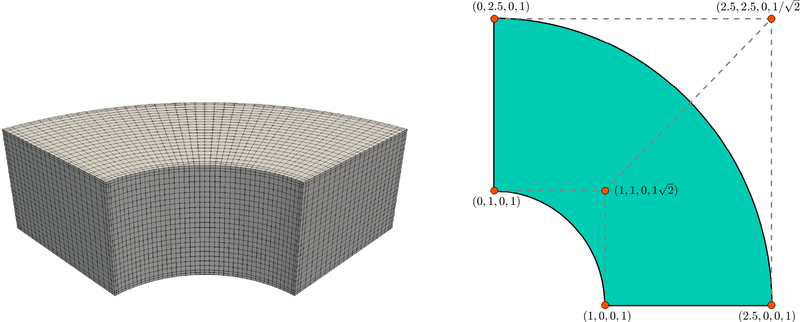
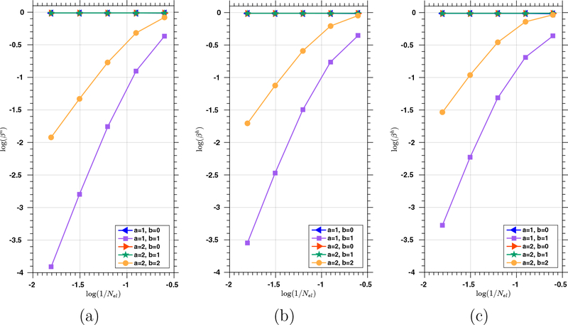
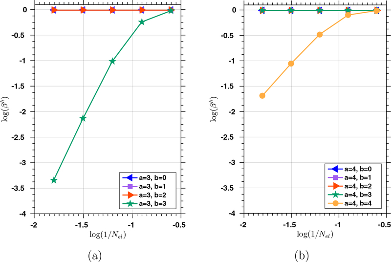
The value of βh is determined as the square root of the smallest non-zero eigenvalue. The regularity vector α = {−1,α, ⋯ ,α,−1} is the same in all three directions. The numerical integration is performed by the Gauss quadrature rule with p + a + 2 quadrature points in each direction to ensure accuracy. The eigenvalues are calculated by the SLEPc package [18]. The trend of βh is examined as we progressively refine the mesh for 0 ≤ b ≤ a. We consider a curved geometry for the domain, which is exactly represented by NURBS and illustrated in Figure 1. The computed values of βh for p = 2, 3, and 4 with 0 ≤ b ≤ a ≤ 2 are presented in Figure 2. It can be observed that βh approaches zero with mesh refinement when a = b. To confirm this observation, we investigate the cases of a = 3 and a = 4 with p fixed to be 2, with results reported in Figure 3. Again, we observe that βh shows a clear trend of approaching zero with mesh refinement only when a = b. To further validate this finding, we also study a unit cube for the domain, which allows us to start the test with p = 1. Again, the same trend of βh is observed. Based on the collected results, we make the following salient observations. For the smooth generalizations of the Taylor-Hood element, if the velocity space is generated by pure k-refinement (i.e., a = b), the resulting element pair is not inf-sup stable. If the velocity space is generated by pure p-refinement from the pressure space (i.e., b = 0), the smallest eigenvalues are bounded below from zero. Also, if a ≥ 2, the velocity spaces generated with 1 ≤ a − b also pass the numerical inf-sup test. This suggests that one may still perform k-refinement to increase the regularity of the velocity space if it is followed by a p-refinement of order at least one.
Figure 1:
The geometry of the thick-walled cylinder (left) and the control net with the control points’ coordinates as well as weights on the bottom plane surface (right). The NURBS basis functions in the circumferential direction are built from the knot vector {0,0,0,1,1,1}. The NURBS basis functions in the radial and axis direction are built from the knot vector {0,0,1,1}.
Figure 2:
The numerical inf-sup test for the thick-walled cylinder using (a) p = 2, (b) p = 3, and (c) p = 4 with 0 ≤ b ≤ a = 2 and Nel elements in each direction.
Figure 3:
The numerical inf-sup test for the thick-walled cylinder domain using p = 2 with (a) 0 ≤ b ≤ a = 3 and (b) 0 ≤ b ≤ a = 4 and Nel elements in each direction.
4.2. Convergence studies
In this example, we investigate the convergence behavior of the proposed numerical scheme. We consider an incompressible Neo-Hookean material model
The geometrical domain is a unit cube with dimension 1m × 1m × 1m. The modulus c1 is chosen as 1 Pa, and the density ρ0 is 1 kg/m3. The analytic forms of the displacement and pressure fields on the referential configuration adopt the following forms,
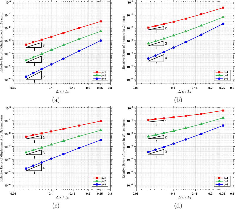
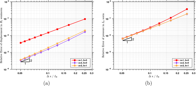
In this example, the reference values are chosen as L0 = 1 m, M0 = 1 kg, T0 = 1 s; both β and γ are chosen to be 2π rad; c and d are non-dimensional parameters that take the value 0.2. On the faces Y = Z = 0 m and Y = Z = 1 m, the body is fully clamped, and traction boundary conditions are applied on the rest faces. For the simulations in the convergence study, we use tolR = 10−10 and tolA = 10−12 as the stopping criteria in the predictor multi-corrector algorithm. Two different time step sizes are used to ensure that the temporal error does not pollute the spatial convergence rate. The relative errors of the displacement and pressure fields are reported in Figure 4 for varying values of p with a = 1, b = 0. We notice immediately that all the errors decrease with the optimal rates. In Figure 5, we report the convergence rates for a = 2, which resembles a smooth generalization of the spectral element [57]. In Figure 5 (a), we note that the increase of the value of a does not improve the convergence rate, regardless of the value of b. Yet, the velocity error is smaller than that of the a = 1 case. From Figure 5 (b), we can see that the pressure errors are almost indistinguishable for a = 1 and a = 2
Figure 4:
The relative errors of (a) the displacement in L2 norm, (b) the pressure in L2 norm, (c) the displacement in H1 seminorm, and (d) the pressure in H1 seminorm, under h-refinement with a = 1 and b = 0.
Figure 5:
The relative errors of (a) the displacement in H1 seminorm and (b) the pressure in L2 norm, under h-refinement with p = 1 and varying values of a and b.
4.3. Three-dimensional compression of a block
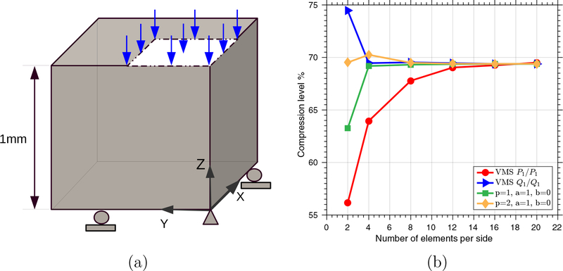
In this example, we examine the performance of the new formulation using the benchmark problem initially designed in [44]. On the boundary faces X = Y = Z = 0, we apply symmetry boundary conditions, and we disallow horizontal displacement on the top surface. A ‘dead’ load with magnitude 3.2 × 10⁸ Pa is applied on a quarter portion of the top surface, which assumes the negative Z-direction in the referential configuration. The block is initially stress free with zero displacement. The surface traction load is applied as a linear function of time and reaches the prescribed magnitude at time T = 1 s. We adopt an incompressible Neo-Hookean model given by the following energy function,
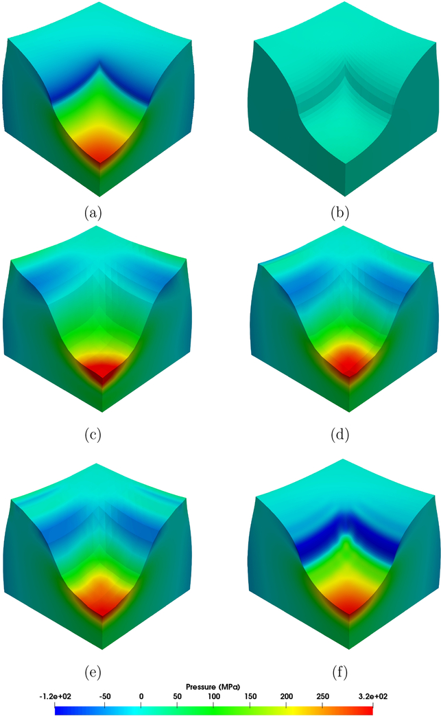
The material properties are chosen as ρ0 = 1.0×10³ kg/m3 and c1 = 8.0194×10⁷ Pa. We simulate the problem with a fixed time step size Δt = 5.0 × 10⁻³ s. We fix the values of a and b to 1 and 0 in this example. For comparison purposes, we also simulate the problem with the variational multiscale (VMS) formulation [41] using equal-order interpolations. As a classical benchmark problem, the primary quantity of interest is the displacement at the upper center point (i.e. the point at X = Y = 0, Z = 1 in the reference configuration). In Figure 6 (b), the compression levels at this point calculated by different methods are illustrated. For the coarsest mesh (two elements per side), the stable element with p = 2 gives a very good prediction of the compression level. It is interesting to note that the equal-order interpolation using the Q1/Q1 element with the VMS formulation gives a fairly good result for a finer mesh with four elements per side. Using a mesh with 8 elements per side, both stable elements give indistinguishable results in comparison with the reference value. In Figure 7, we further compare the pressure profiles at the current configuration calculated by the proposed formulation as well as the VMS formulation. The pressure profile calculated by a fine mesh (6×1923 linear tetrahedral elements using the VMS formulation with equal-order linear interpolations) is depicted to serve as a reference solution profile. Using the same VMS formulation, the pressure field calculated by 6 × 483 linear tetrahedral elements is demonstrated in Figure 7 (b), which clearly shows a very poor approximation quality. In our experience, the VMS formulation using low-order elements always requires mesh convergence studies to deliver trustworthy stress calculations, and oftentimes this procedure eventually demands very high mesh resolutions. Using the proposed mixed formulation with 2 elements per side and varying values of p, it can be observed that the calculated pressure fields are always in good agreement with the reference solution profile. The increase of the polynomial degree p improves the solution quality. For the case of p = 2 with 20 elements per side, the calculated result captures the major feature of the pressure field and confirms the convergence of the pressure field.
Figure 6:
Three-dimensional block compression: (a) geometry setting; (b) compression level in % versus the number of elements per side.
Figure 7:
Three-dimensional block compression: pressure profile in the current configuration with (a) the VMS formulation and 6 × 1923 linear tetrahedral elements, (b) the VMS formulation and 6 × 483 linear tetrahedral elements, (c) p = 2, Δx = 1/2, (d) p = 4, Δx = 1/2, (e) p = 6, Δx = 1/2, and (f) p = 2, Δx = 1/20.
4.4. Tensile test of an anisotropic fiber-reinforced hyperelastic soft tissue specimen
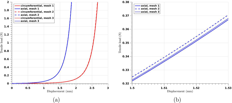
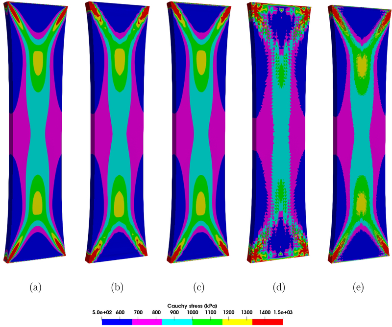
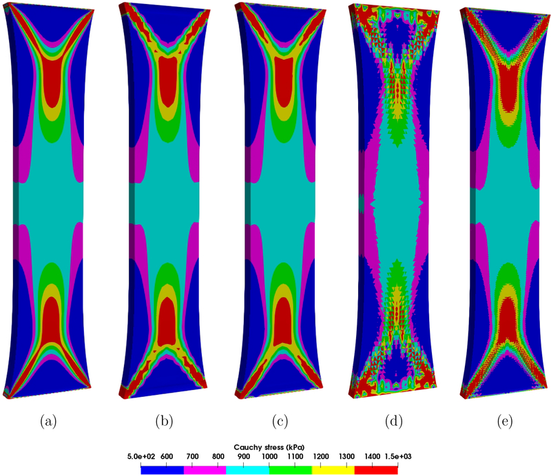
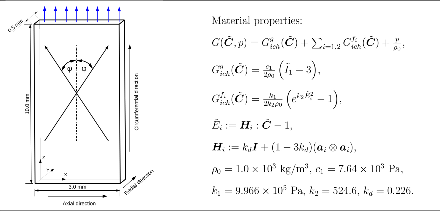
In this example, we examine the performance of the proposed formulation for an incompressible anisotropic hyperelastic material, which has been designed to describe arterial tissue layers with distributed collagen fibers [14]. We note that this material model used in the compressible regime may lead to non-physical deformations [17, 47], and remedies for this issue have been proposed recently [16]. The geometry set-up and the material model are summarized in Table 1. The groundmatrix is modeled as an isotropic Neo-Hookean material, with c1 being the shear modulus. The ith family of collagen fibers is modeled by an exponential function . The unit vector ai characterizes the mean orientation of the fiber, and κd is a dispersion parameter that characterizes the distribution of the collagen fibers. In this study, we assume the mean orientation of the two families of fibers has no component in the radial direction and is completely determined by φ, the angle between the fiber orientation and the loading direction. For a circumferential specimen, the tensile load is along the circumferential direction and φ = 49.98°; correspondingly, for an axial specimen, the value of φ is 40.02°. We consider only one-eighth of the specimen by applying symmetry boundary conditions. On the loading surface, a master-slave relation is enforced for the nodes to ensure that the surface moves only in the loading direction. The loading traction is applied gradually and reaches 2 N in 200 seconds. We simulate the problem with a fixed time step size Δt = 2.0 × 10⁻² s. Three different meshes are used for the proposed formulation (See Table 2). In Figure 8, the load-displacement curves calculated by the three different meshes for the circumferential and axial specimen are plotted. It is hard to distinguish the results in Figure 8 (a). In Figure 8 (b), we provide a detailed comparison near the tensile load 0.35 N. The curve obtained from mesh 3 is still very close to the reference solid line, indicating improved accuracy with increasing polynomial degree. For comparison purposes, we present the stress results calculated by the VMS formulation [41] with linear tetrahedral elements using two different spatial resolutions (see Table 2). From Figures 9 and 10, we observe that the essential feature of the Cauchy stress is captured in mesh 2, although there are slight oscillations near the corners. The results calculated from the mesh 1 and mesh 3 are almost indistinguishable, indicating that increasing the polynomial degree improves the accuracy of the stress results. In contrast, the stress is poorly resolved in the mesh 4 due to the low-order elements. The results of mesh 5 illustrate that mesh refinement helps improve the quality of the stress results. Yet, one can still observe a discontinuous pattern and oscillations of the stress profile. Notice that the meshes 2, 3, and 4 have about the same number of degrees of freedom (see Table 2). The striking differences in the results again demonstrate the superior approximation properties in stress calculations when using higher-order elements within the proposed provably stable formulation.
Table 1:
Three-dimensional tensile test: geometry setting and material properties.
|
Table 2:
The number of elements nen, the number of elements in the radial direction , and the number of equations neq in the system (30) for the five different meshes. Meshes 1 and 3 consist of NURBS element with p = 2; mesh 2 consists of NURBS element with p = 1; meshes 4 and 5 consist of linear tetrahedral elements. For meshes 1, 2, and 3, the values of a and b are fixed to be 1 and 0.
| Mesh | 1 | 2 | 3 | 4 | 5 |
|---|---|---|---|---|---|
| nen | 61440 | 120 | 120 | 5760 | 90000 |
| 8 | 1 | 1 | 2 | 5 | |
| neq | 1785024 | 5091 | 7584 | 6396 | 75144 |
Figure 8:
Three-dimensional tensile test: (a) computed load-displacement curves of the circumferential (red) and axial specimens (blue) using different meshes; (b) detailed comparison of the computed load-displacement curves near the tensile load 0.35 N.
Figure 9:
Three-dimensional tensile test: σzz for the axial specimen calculated by (a) mesh 1, (b) mesh 2, (c) mesh 3, (d) mesh 4, and (e) mesh 5 on the deformed configurations at the tensile load 1 N. See Table 2 for details of the meshes.
Figure 10:
Three-dimensional tensile test: σzz for the circumferential specimen calculated by (a) mesh 1, (b) mesh 2, (c) mesh 3, (d) mesh 4, and (e) mesh 5 on the deformed configurations at the tensile load 1 N. See Table 2 for details of the meshes.
4.5. Three-dimensional beam bending
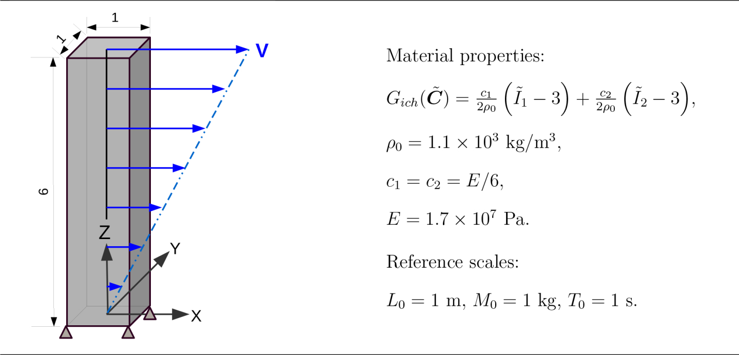
In this example, we present a three-dimensional beam vibration problem to evaluate the performance of the elastodynamics formulation in a bending dominated scenario [5]. The problem configuration as well as the material properties are illustrated in Table 3. The beam is fully clamped at the base, and the other faces are specified by zero tractions. The body is initially stress free with zero displacement. The vibration is initiated through an initial velocity
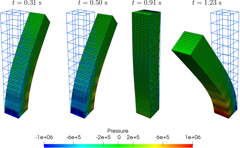
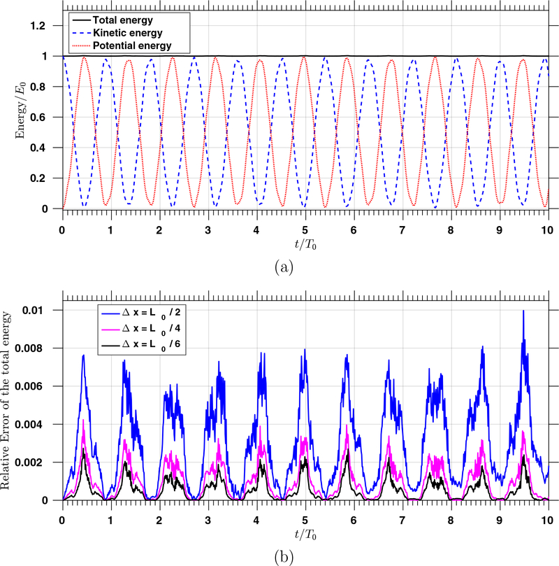
This initial condition leads to an oscillatory motion of the beam. For the simulations, we choose p = 1, a = 1, and b = 0 for the discrete function spaces. The numerical results show the deformation state of the beam calculated from the two different meshes are indistinguishable, suggesting a coarse mesh with Δx = L0/2 is capable of accurately describing the beam dynamics (Figure 11). Since the boundary data is time independent and the body force and surface tractions are zero, the total energy of the beam is conserved according to Proposition 1. We observe that the total energy is well-preserved up to T = 10 s (Figure 12 (a)). From the periodic pattern of the kinetic and potential energies, we obtain an average period of the oscillation is 0.9018 s. To better illustrate the energy conservation, we plot the relative errors of the energy in Figure 12 (b), using three different spatial meshes. Interestingly, the error of the total energy achieves its maximum value when the beam reaches its largest deformation. For the coarsest mesh (Δx = L0/2), the error accumulates slightly over time, and we can see that the relative error reaches about one percent at around 9.5 s. We also observe that the spatial mesh refinement helps reduce the error of the total energy. For the meshes with Δx = L0/4 and Δx = L0/6, we do not observe a pile-up effect of the energy error. Also, the magnitude of the relative error is reduced with mesh refinement. In comparison with the previously published results [2, 36], the new formulation enjoys a better discrete energy conservation property.
Table 3:
Three-dimensional beam bending: geometry setting, boundary conditions, and material properties.
|
Figure 11:
Snapshots of the vibrating beam: The pressure field at different time steps using mesh size Δx = L0/2 and time step size Δt = 10−3T0. The deformation states at the corresponding time steps using mesh size Δx = L0/12 and time step size Δt = 10−4T0 are shown as the black grid. The light blue grid shows the mesh with size Δx = L0/2 at time t = 0.
Figure 12:
(a) The total, kinetic, and potential energies over time with Δx = L0/6; (b) The relative error of the total energy over time. The simulations are performed with p = 1, a = 1, b = 0, and Δt = 2 × 10⁻⁴T0. The reference value of the total energy E0 is chosen to be the total energy at time t = 0, which is 1.1 × 10⁵ kg m2/S2.
4.6. A spinning annular disk
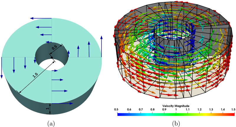
In this example, we study a spinning annular disk with zero traction boundary condition imposed on all boundary faces. In Figure 13 (a), the geometrical setting is illustrated. The inner radius of the disk is 0.5 m, the outer radius is 1.5 m, and the thickness is 1 m. The material of the disk is Neo-Hookean with density ρ0 = 10 kg/m3 and shear modulus c1 = 7.5 Pa. Both the geometrical and material settings follow the benchmark example in [35]. The initial displacement is zero, and the spinning motion is initiated by an initial angular velocity of 1 rad/s in the x-y plane, that is
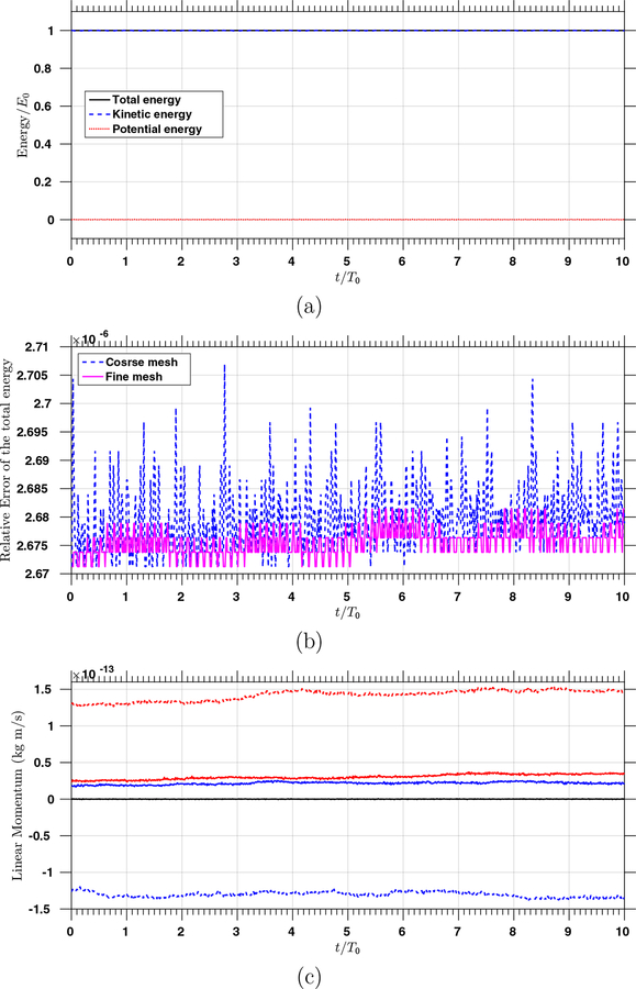
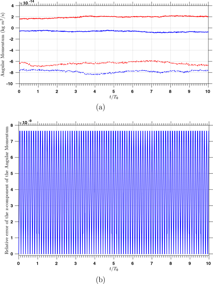
We choose the reference scales as L0 = 1 m, M0 = 1 kg, and T0 = 1 s. The geometry of the domain can be exactly parametrized by connecting four thick-walled cylinders shown in Figure 1 and adjusting the coordinates of the control points. Therefore, we have p = 2 for the discrete pressure function space. The geometry is C1 except at the four connecting surfaces where the continuity reduces to C0. We choose a = 1 and b = 0 for generating the discrete velocity function space. A coarse mesh is generated with 32 elements in the circumferential direction, 4 elements in the radial direction, and 4 elements in the axial direction; a fine mesh is generated with 64 elements in the circumferential direction, 8 elements in the radial direction, and 8 elements in the axial direction. The time step size is Δt = 2×10⁻⁴ s, and the problem in integrated up to T = 10.0 s. In Figure 13 (b), a snapshot of the simulated velocity in the annular disk is depicted. Due to the zero traction boundary condition and the zero body force, this problem serves as a benchmark for examining the energy stability as well as the momentum conservation properties. In Figure 14 (a), we can see that the kinetic energy and the total energy are nicely conserved. In Figure 14 (b), the relative errors of the total energy over time are plotted, which are uniformly smaller than 3×10⁻⁶. The exact value of the linear momentum is zero, and we see that the absolute errors are less than 1.5 × 10⁻¹³ in Figure 14 (c). The x- and y-components of the angular momentum are zero, with numerical values having absolute errors less than 10−13 (Figure 15). The analytic value of the z-component of the angular momentum is 78.5 kg·m2/s, and we depict its relative error from the simulation with the coarse mesh. Note that the error of the z-component of the angular momentum is highly oscillatory and is bounded by 8 × 10⁻⁹. The numerical results corroborate the estimates given in Section 3.2.
Figure 13:
The three-dimensional spinning annular disk: (a) the geometrical setting and the initial condition; (b) a snapshot of the velocity field.
Figure 14:
(a) The total, kinetic, and potential energies over time using the coarse mesh scaled by E0 = 29.27 J, which is the initial total energy; (b) The relative errors of the total energy over time for the two different meshes; (c) The x-, y-, and z-components of the linear momentum are plotted in the blue, red, and black colors respectively, and the results for the fine mesh and coarse mesh are plotted in solid and dashed lines respectively.
Figure 15:
(a) The x- and y-components of the angular momentum are plotted in the blue and red colors respectively, and the results for the fine mesh and coarse mesh are plotted in solid and dashed lines respectively; (b) The relative error of the z-component of the angular momentum over time for the coarse mesh.
5. Conclusions and future work
In this work, we presented a new numerical formulation for incompressible hyper-elastodynamics. We have revealed that the proposed formulation possesses a physically compatible notion of numerical stability, and the inf-sup condition can be utilized to give a bound for the pressure. These properties favorably distinguish the proposed formulation from previously existing ones [19, 30, 43, 55]. We use smooth generalizations of the Taylor-Hood element based on NURBS for the spatial discretization, aiming to provide a higher-order method that is stable, robust, and implementationally convenient. The inf-sup stability for the elements is elucidated through numerical assessment. A variety of benchmark examples are simulated to investigate the effectiveness of the method in different loading conditions and for different material models. In particular, two dynamic problems are studied to verify the numerical stability and conservation properties.
In addition to the superior accuracy in stress calculations, the adoption of NURBS elements makes the description of material anisotropy convenient because the mesh naturally aligns along the axial, circumferential, and radial directions. These attributes make the proposed formulation a promising candidate for biomedical problems. Based on the proposed formulation, the anisotropic arterial wall model will be further refined with detailed stress-driven mass production and removal for individual constituents that comprise the tissue. This will lead to a three-dimensional patientspecific predictive tool for vascular growth and remodeling. On the theoretical side, the energy stability of the proposed formulation guarantees boundedness of the deformation state. This property makes the method a promising candidate in detecting the stability range for incompressible finite elasticity [48].
Acknowledgements
This work is supported by the National Institutes of Health (NIH) under the award numbers 1R01HL121754 and 1R01HL123689, the National Science Foundation (NSF) CAREER award OCI-1150184, and computational resources from the Extreme Science and Engineering Discovery Environment supported by the NSF grant ACI-1053575. The authors acknowledge TACC at the University of Texas at Austin for providing computing resources that have contributed to the research results reported within this paper.
References
- [1].Abboud N and Scovazzi G. Elastoplasticity with linear tetrahedral elements: A variational multiscale method. International Journal for Numerical Methods in Engineering, 115:913–955, 2018. [Google Scholar]
- [2].Aguirre M, Gil AJ, Bonet J, and Carreño AA. A vertex centred finite volume JamesonSchmidt-Turkel (JST) algorithm for a mixed conservation formulation in solid dynamics. Journal of Computational Physics, 259:672–699, 2014. [Google Scholar]
- [3].Auricchio F, Beirão da Veiga L, Lovadina C, and Reali A. A stability study of some mixed finite elements for large deformation elasticity problems. Computer Methods in Applied Mechanics and Engineering, 194:1075–1092, 2005. [Google Scholar]
- [4].Boffi D, Brezzi F, and Fortin M. Mixed Finite Element Methods and Applications. Springer, 2013. [Google Scholar]
- [5].Bonet J, Gil AJ, Lee CH, Aguirre M, and Ortigosa R. A first order hyperbolic framework for large strain computational solid dynamics. Part I: Total Lagrangian isothermal elasticity. Computer Methods in Applied Mechanics and Engineering, 283:689–732, 2015. [Google Scholar]
- [6].Bonet J, Gil AJ, and Ortigosa R. A computational framework for polyconvex large strain elasticity. Computer Methods in Applied Mechanics and Engineering, 283, 1061–1094 2015. [Google Scholar]
- [7].Chapelle D and Bathe KJ. The Inf-Sup test. Computers & Structures, 47:537–545, 1993. [Google Scholar]
- [8].Chung J and Hulbert GM. A time integration algorithm for structural dynamics with improved numerical dissipation: the generalized-α method. Journal of applied mechanics, 60:371–375, 1993. [Google Scholar]
- [9].Cottrell JA, Reali A, Bazilevs Y, and Hughes TJR. Isogeometric analysis of structural vibrations. Computer Methods in Applied Mechanics and Engineering, 195:5257–5296, 2006. [Google Scholar]
- [10].de Souza Neto EA, Perić D, Dutko M, and Owen DRJ. Design of simple low order finite elements for large strain analysis of nearly incompressible solids. International Journal of Solids and Structures, 33:3277–3296, 1996. [Google Scholar]
- [11].Dortdivanlioglu B, Krischok A, Beirão da Veiga L, and Linder C. Mixed isogeometric analysis of strongly coupled diffusion in porous materials. International Journal for Numerical Methods in Engineering, 114:28–46, 2017. [Google Scholar]
- [12].Elguedj T, Bazilevs Y, Calo VM, and Hughes TJR. and projection methods for nearly incompressible linear and non-linear elasticity and plasticity using higher-order NURBS elements. Computer Methods in Applied Mechanics and Engineering, 197:2732–2762, 2008. [Google Scholar]
- [13].Evans JA and Hughes TJR. Isogeometric divergence-conforming B-splines for the DarcyStokes-Brinkman equations. Mathematical Models and Methods in Applied Sciences, 23:671–741, 2013. [Google Scholar]
- [14].Gasser TC, Ogden RW, and Holzapfel GA. Hyperelastic modelling of arterial layers with distributed collagen fibre orientations. Journal of the Royal Society Interface, 3:15–35, 2006. [DOI] [PMC free article] [PubMed] [Google Scholar]
- [15].Gil AJ, Lee CH, Bonet J, and Ortigosa R. A first order hyperbolic framework for large strain computational solid dynamics. Part II: Total Lagrangian compressible, nearly incompressible and truly incompressible elasticity. Computer Methods in Applied Mechanics and Engineering, 300:146–181, 2016. [Google Scholar]
- [16].Gultekin O, Dal H, and Holzapfel GA. On the quasi-incompressible finite element analysis of anisotropic hyperelastic materials. Computational Mechanics, 63:443–453, 2019. [Google Scholar]
- [17].Helfenstein J, Jabareen M, Mazza E, and Govindjee S. On non-physical response in models for fiber-reinforced hyperelastic materials. International Journal of Solids and Structures, 47:2056–2061, 2010. [Google Scholar]
- [18].Hernandez V, Roman JE, and Vidal V. SLEPc: A scalable and flexible toolkit for the solution of eigenvalue problems. ACM Trans. Math. Software, 31:351–362, 2005. [Google Scholar]
- [19].Hoffman J, Jansson J, and Stöckli M. Unified continuum modeling of fluid-structure interaction. Mathematical Models and Methods in Applied Sciences, 21:491–513, 2011. [Google Scholar]
- [20].Holm DD, Marsden JE, Ratiu T, and Weinstein A. Nonlinear stability of fluid and plasma equilibria. Physics reports, 123:1–116, 1985. [Google Scholar]
- [21].Holzapfel GA. Nonlinear Solid Mechanics: A Continuum Approach for Engineering. John Wiley & Sons, 2000. [Google Scholar]
- [22].Hood P and Taylor C. Numerical solution of the Navier-Stokes equations using the finite element technique. Computers & Fluids, 1:1–28, 1973. [Google Scholar]
- [23].Hughes TJR. Equivalence of finite elements for nearly incompressible elasticity. Journal of Applied Mechanics, 44:181–183, 1977. [Google Scholar]
- [24].Hughes TJR. The Finite Element Method: Linear Static and Dynamic Finite Element Analysis. Prentice Hall, Englewood Cliffs, NJ, 1987. [Google Scholar]
- [25].Hughes TJR. Multiscale phenomena: Green’s functions, the Dirichlet-to-Neumann formulation, subgrid scale models, bubbles and the origins of stabilized methods. Computer Methods in Applied Mechanics and Engineering, 127:387–401, 1995. [Google Scholar]
- [26].Hughes TJR, Cottrell JA, and Bazilevs Y. Isogeometric analysis: CAD, finite elements, NURBS, exact geometry and mesh refinement. Computer Methods in Applied Mechanics and Engineering, 194:4135–4195, 2005. [Google Scholar]
- [27].Hughes TJR, Franca LP, and Balestra M. A new finite element formulation for computational fluid dynamics: V. Circumventing the Babuška-Brezzi condition: A stable PetrovGalerkin formulation of the Stokes problem accommodating equal-order interpolations. Computer Methods in Applied Mechanics and Engineering, 59:85–99, 1986. [Google Scholar]
- [28].Hughes TJR, Taylor RL, and Sackman JL. Finite element formulation and solution of contact-impact problems in continuum mechanics-III, SESM Report 75–3 Technical report, Department of Civil Engineering, The University of California, Berkeley, 1975. [Google Scholar]
- [29].Hughes TJR and Winget J. Finite rotation effects in numerical integration of rate constitutive equations arising in large-deformation analysis. International journal for numerical methods in engineering, 15:1862–1867, 1980. [Google Scholar]
- [30].Idelsohn SR, Marti J, Limache A, and Oñate E. Unified Lagrangian formulation for elastic solids and incompressible fluids: Application to fluid-structure interaction problems via the PFEM. Computer Methods in Applied Mechanics and Engineering, 197:1762–1776, 2008. [Google Scholar]
- [31].Jansen KE, Whiting CH, and Hulbert GM. A generalized-α method for integrating the filtered Navier-Stokes equations with a stabilized finite element method. Computer Methods in Applied Mechanics and Engineering, 190:305–319, 2000. [Google Scholar]
- [32].Kadapa C, Dettmer WG, and Perić D. Subdivision based mixed methods for isogeometric analysis of linear and nonlinear nearly incompressible materials. Computer Methods in Applied Mechanics and Engineering, 305:241–270, 2016. [Google Scholar]
- [33].Kadapa C, Dettmer WG, and Perić D. On the advantages of using the first-order generalised-alpha scheme for structural dynamic problems. Computers & Structures, 193:226–238, 2017. [Google Scholar]
- [34].Klaas O, Maniatty A, and Shephard MS. A stabilized mixed finite element method for finite elasticity.: Formulation for linear displacement and pressure interpolation. Computer Methods in Applied Mechanics and Engineering, 180:65–79, 1999. [Google Scholar]
- [35].Kruüger M, Groß M, and Betsch P. An energy-entropy-consistent time stepping scheme for nonlinear thermo-viscoelastic continua. ZAMM-Journal of Applied Mathematics and Mechanics/Zeitschrift für Angewandte Mathematik und Mechanik, 96:141–178, 2016. [Google Scholar]
- [36].Lahiri SK, Bonet J, Peraire J, and Casals L. A variationally consistent fractional timestep integration method for incompressible and nearly incompressible lagrangian dynamics. International Journal for Numerical Methods in Engineering, 63:1371–1395, 2005. [Google Scholar]
- [37].Lipton S, Evans JA, Bazilevs Y, Elguedj T, and Hughes TJR. Robustness of isogeometric structural discretizations under severe mesh distortion. Computer Methods in Applied Mechanics and Engineering, 199:357–373, 2010. [Google Scholar]
- [38].Liu CH, Hofstetter G, and Mang HA. 3D finite element analysis of rubber-like materials at finite strains. Engineering Computations, 11:111–128, 1994. [Google Scholar]
- [39].Liu J, Gomez H, Evans JA, Hughes TJR, and Landis CM. Functional Entropy Variables: A New Methodology for Deriving Thermodynamically Consistent Algorithms for Complex Fluids, with Particular Reference to the Isothermal Navier-Stokes-Korteweg Equations. Journal of Computational Physics, 248:47–86, 2013. [Google Scholar]
- [40].Liu J, Landis CM, Gomez H, and Hughes TJR. Liquid-Vapor Phase Transition: Thermomechanical Theory, Entropy Stable Numerical Formulation, and Boiling Simulations. Computer Methods in Applied Mechanics and Engineering, 297:476–553, 2015. [Google Scholar]
- [41].Liu J and Marsden AL. A unified continuum and variational multiscale formulation for fluids, solids, and fluid-structure interaction. Computer Methods in Applied Mechanics and Engineering, 337:549–597, 2018. [DOI] [PMC free article] [PubMed] [Google Scholar]
- [42].Liu J and Marsden AL. A robust and efficient iterative method for hyper-elastodynamics with nested block preconditioning. Journal of Computational Physics, 383:72–93, 2019. [DOI] [PMC free article] [PubMed] [Google Scholar]
- [43].Liu WK, Belytschko T, and Chang H. An arbitrary lagrangian-eulerian finite element method for path-dependent materials. Computer Methods in Applied Mechanics and Engineering, 58:227–245, 1986. [Google Scholar]
- [44].Reese S, Wriggers P, and Reddy BD. A new locking-free brick element technique for large deformation problems in elasticity. Computers & Structures, 75:291–304, 2000. [Google Scholar]
- [45].Rossi S, Abboud N, and Scovazzi G. Implicit finite incompressible elastodynamics with linear finite elements: A stabilized method in rate form. Computer Methods in Applied Mechanics and Engineering, 311:208–249, 2016. [Google Scholar]
- [46].Rüberg T and Cirak F. Subdivision-stabilised immersed b-spline finite elements for moving boundary flows. Computer Methods in Applied Mechanics and Engineering, 209:266–283, 2012. [Google Scholar]
- [47].Sansour C. On the physical assumptions underlying the volumetric-isochoric split and the case of anisotropy. European Journal of Mechanics-A/Solids, 27:28–39, 2008. [Google Scholar]
- [48].Schröder J, Viebahn N, Wriggers P, Auricchio F, and Steeger K. On the stability analysis of hyperelastic boundary value problems using three- and two-field mixed finite element formulations. Computational Mechanics, 60:479–492, 2017. [Google Scholar]
- [49].Scovazzi G, Carnes B, Zeng X, and Rossi S. A simple, stable, and accurate linear tetrahedral finite element for transient, nearly, and fully incompressible solid dynamics: a dynamic variational multiscale approach. International Journal for Numerical Methods in Engineering, 106:799–839, 2016. [Google Scholar]
- [50].Shakib F, Hughes TJR, and Johan Z. A new finite element formulation for computational fluid dynamics: X. The compressible Euler and Navier-Stokes equations. Computer Methods in Applied Mechanics and Engineering, 89:141–219, 1991. [Google Scholar]
- [51].Simo JC and Armero F. Geometrically non-linear enhanced strain mixed methods and the method of incompatible modes. International Journal for Numerical Methods in Engineering, 33:1413–1449, 1992. [Google Scholar]
- [52].Simo JC and Pister KS. Remarks on rate constitutive equations for finite deformation problems: computational implications. Computer Methods in Applied Mechanics and Engineering, 46:201–215, 1984. [Google Scholar]
- [53].Simo JC and Rifai MS. A class of mixed assumed strain methods and the method of incompatible modes. International Journal for Numerical Methods in Engineering, 29:1595–1638, 1990. [Google Scholar]
- [54].Simo JC, Tarnow N, and Wong KK. Exact energy-momentum conserving algorithms and symmetric schemes for nonlinear dynamics. Computer Methods in Applied Mechanics and Engineering, 100:63–116, 1992. [Google Scholar]
- [55].Sussman T and Bathe KJ. A finite element formulation for nonlinear incompressible elastic and inelastic analysis. Computers & Structures, 26:357–409, 1987. [Google Scholar]
- [56].Wriggers P and Reese S. A note on enhanced strain methods for large deformations. Computer Methods in Applied Mechanics and Engineering, 135:201–209, 1996. [Google Scholar]
- [57].Yu Y, Baek H, Bittencourt M, and Karniadakis GE. Mixed spectral/hp element formulation for nonlinear elasticity. Computer Methods in Applied Mechanics and Engineering, 213:42–57, 2012. [Google Scholar]
- [58].Zeng X, Scovazzi G, Abboud N, Colomés O, and Rossi S. A dynamic variational multiscale method for viscoelasticity using linear tetrahedral elements. International Journal for Numerical Methods in Engineering, 112:1951–2003, 2017. [Google Scholar]


