Abstract
Accurate placement and stable fixation are the main goals of internal fixation of bone fractures using the traditional medical screws. These goals are necessary to expedite and avoid improper fracture healing due to misalignment of the bone fragments. However, the rigidity of the screw, geometry of the fractured anatomy (e.g., femur and pelvis), and osteoporosis may cause an array of complications. To address these challenges, we propose the use of a continuum manipulator and a bendable medical screw (BMS) to drill curved tunnels and fixate the bone fragments. This novel approach provides the clinicians with a degree of freedom in selecting the drilling entry point as well as the navigation of drill in complex anatomical and osteoporotic bones. This technique can also facilitate the treatment of osteonecrosis and augmentation of the hip to prevent osteoporotic fractures. In this paper: 1) we evaluated the performance of the curved drilling technique on human cadaveric specimens by making several curved tunnels with different curvatures and 2) we also demonstrated the feasibility of internal fixation using the BMS versus a rigid straight screw by performing finite element simulation of fracture fixation in an osteoporotic femur.
Index Terms—: Medical robots and systems, continuum manipulator, medical device design, orthopedic surgery
I. INTRODUCTION
IN RECENT years, continuum manipulators (CMs) have attracted much attention in the medical robotics field. This is mainly due to the added dexterity and accessibility that CMs provide to surgeons in confined environments, potentially minimizing patient trauma and hospitalization time in various minimally invasive surgical procedures [1]. A review of literature indicates that these dexterous robots have been designed and utilized mostly for interventions involving soft tissues (e.g., cardiac [2], head and neck [3], and endonasal [4] applications). However, the main drawback of these CMs is their low structural stability and stiffness, making them ill-suited for orthopedic applications.
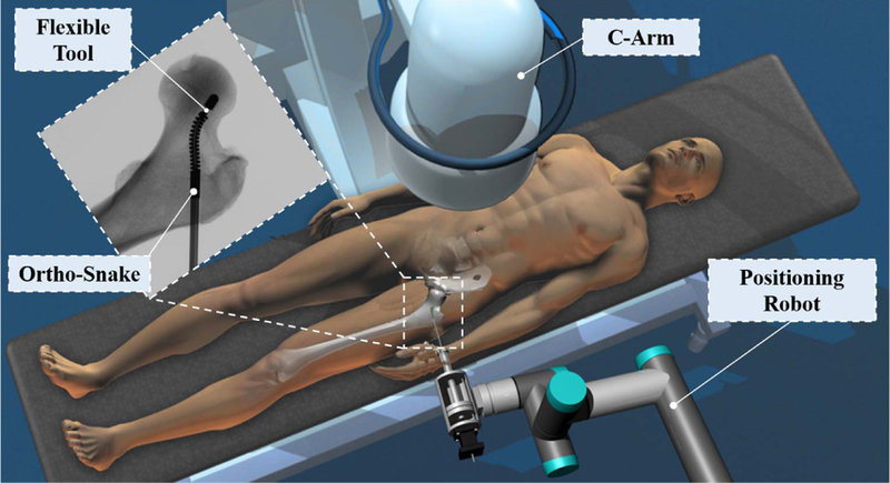
To address the trade-off between dexterity and structural stability, our group is developing surgical robotic systems (Fig. 1) to be used in various orthopedic interventions (e.g., [5] and [6]). The core of this surgical system is a continuum manipulator, called “ortho-snake”, designed to provide high dexterity and structural stability for orthopedic interventions. We also have developed flexible tools that can pass through the ortho-snake’s instrument channel in order to perform drilling and milling procedures. The performance of this system has been evaluated on orthopedic interventions such as minimally invasive treatment of hip osteolytic lesions [5] and osteonecrosis of the femoral head [6], [7].
Fig. 1.
Conceptual illustration of the proposed robotic workstation designed for orthopedic applications. This system comprises of a positioning robot, a continuum manipulator (i.e., ortho-snake), and proper flexible cutting and fixation tools.
In [8], we evaluated the feasibility of using our system for internal fixation of bone fractures. In this common orthopedic procedure, typically a rigid cannulated screw is used to fixate fragments of a fractured bone in order to expedite the healing process [9]. However, the rigidity of the utilized drill bit imposes constraints on the drilling trajectory (i.e., drilling on a straight path) and the choice of entry point of drilling for surgeons. Hence, this common procedure can become very sophisticated in anatomies having complex geometries (e.g., pelvis or femoral head) and/or weakened by osteoporosis. For instance, internal fixation of the femoral head in elderly patients often has a low success rate [10]. This is mainly due to the fact that the rigid screw is typically implanted into osteoporotic bone and, therefore, cannot provide sufficient hold during the healing process. Furthermore, to ensure patient’s safety, this procedure often requires multiple trials leading to an increase in surgery time and cost as well as radiation exposure to patient and clinicians [8]–[10].
To address the challenges of this procedure, in [8], we proposed using the curved drilling technique with ortho-snake to provide surgeons with sufficient flexibility to set the drilling path within the bone. In addition, we designed and fabricated a cannulated bendable medical screw (BMS) in order to fixate the bone fragments. The feasibility of curved drilling technique was then evaluated by performing various experiments on 15 PCF polyurethane foam (Sawbones; Pacific Research Laboratories, Washington, USA) as a surrogate for human cancellous bones.
To summarize, our contributions are as follows: (i) to complement and extend our previous studies on sawbone samples and evaluate the performance of the proposed robotic system in a more realistic situation, we conduct experiments on human cadaveric specimens; (ii) in [8], we successfully evaluated the passive morphability and self-tapping capability of the designed cannulated BMS on curved tunnels drilled inside the simulated bone materials. In the present work, however, we focused on the load bearing and fixation capability of the BMS using finite element analysis. To analyze this important feature of the BMS, we considered a biomechanical case study in which we simulated a femoral neck fracture weakened by osteoporosis. We compared the fixation capability of the BMS with a rigid straight screw in the presence of a realistic human gait load.
The remainder of this paper is organized as follows. In Section II, we present the elements of our steerable robotic system as well as the design and fabrication procedure of the BMS. The evaluation experiments and their corresponding results are explained in Section III. Experimental results are discussed and concluded in Section IV.
II. DEXTEROUS ROBOTIC SYSTEM AND SCREW
Placement of rigid fixation screws inside bones with complex curved anatomies (e.g., the femoral head, pelvis, and bones in the shoulders, wrist) is the main challenge faced during the internal fixation of bone fractures [7], [9], [10]. The lack of dexterity and ability to steer when using drilling devices for fixation implants may result in an improper bone reunion due to misalignment of the bone fragments. To address this problem, we introduce a robotic assisted procedure using our surgical workstation. As shown in Fig. 1, this system comprises of a positioning robot, a continuum manipulator (i.e., ortho-snake), and proper flexible cutting and fixation tools. In this surgical system, ortho-snake and its actuation unit are integrated with a six degree-of-freedom positioning robotic arm and are simultaneously controlled to perform the assigned control objective as detailed in [11]. In the proposed internal fixation approach, first, the broken bone is reduced or put back into place. Then, based on the clinician’s decision, a curved tunnel is drilled utilizing our steerable robotic system. Finally, a BMS is utilized and placed inside the drilled tunnel to fixate the bone and bring the surfaces of the fracture in close proximity and compression. In the remainder of this section, we describe our robotic system together with the flexible fixation implant.
A. Steerable Drilling System
The following describes the elements of our steerable drilling systems including the ortho-snake, flexible drilling tools, and actuation mechanism of the ortho-snake and tools.
1). Ortho-Snake:
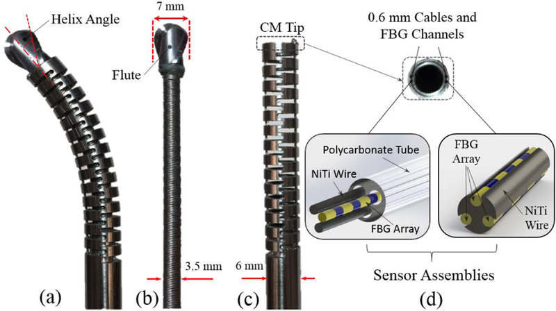
Ortho-snake, as the core of our steerable drilling system, is a cable-driven continuum manipulator specifically designed to provide both steerability and structural stiffness for orthopedic applications. As shown in Fig. 2, it is constructed of two nested pieces of superelastic Nitinol tubes with outer diameter of 6 mm and an inner lumen of 4 mm for passing different type of tools [5]. Thanks to the specific geometry of the notches created by post-machining via a wire EDM process with 35 mm length, the ortho-snake is capable of planar bending to large curvatures up to 166.7 m−1 [12]. As shown in Fig. 2d, to capture the degree of this curvature, two 500μm Fiber Bragg Grating (FBG) optical sensor assemblies are embedded in two channels (0.6 mm diameter) in the walls of the ortho-snake [12]. Each FBG sensor assembly includes three fiber arrays (each 150μm diameter) with three FBG sensing nodes (Technica Optical Components, China). These optical fibers have been carefully integrated within the engraved grooves (radially 120◦ apart from each other) of a 500μm Nitinol wire. The detailed design of this sensor assembly and its fabrication procedure can be found in [12]. Further, the other two 0.5 mm embedded channels inside the ortho-snake’s wall thickness are used for passing two tendons for bending control of the robot to achieve C- and S-shapes (Fig. 2d) [13].
Fig. 2.
(a) Ortho-snake (outer diameter =6 mm) with the flexible end-mill cutting tool passed through its 4 mm instrument channel; (b) ball-end carbide end mill with a shaft diameter of 7 mm, two flutes and helixangle of 30 degree; (c) ortho-snake with outer diameter =6mm and instrument channel = 4 mm; (d) Fiber Bragg Grating (FBG) optical sensor assembly inserted into the 0.6 mm channels of ortho-snake.
2). Flexible Drilling Tool:
Fig. 2 shows the fabricated flexible drilling tool to be inserted inside the ortho-snake’s 4 mm instrument channel. The end-mill head of this custom-designed flexible tool was chosen after studying the performance of different types of cutting tools designed for both side-cutting and penetration. The tool consists of a rigid stainless steel tube (2.8 mm outer diameter), a 3.25 mm flexible torque coil (Asahi Intec USA, Inc.) with 35 mm length, and an oil-less bush (outer diameter = 6.5 mm, inner diameter 4.5 mm). As shown in Fig. 2b, a ball-end carbide end mill with a shaft diameter of 7 mm, two flutes and helix angle of 30 degree (8878A18, McMaster-Carr) has been glued to the flexible torque coil. To insert the 17 mm cutter into the torque coil, we machined the end mill shaft to 3 mm and 7 mm in length.
Diameter of the tool was selected to ensure that it would fit inside the ortho-snake. Additionally, the outer diameter of the cutting tool was chosen to be larger than the outer diameter of ortho-snake in order to minimize buckling of the tool during drilling procedure. We have successfully evaluated the performance of this flexible cutting tool with this particular geometry in cutting synthetic bone models (Sawbones; Pacific Research Laboratories, Washington, USA) both in straight and curved drilling trajectories [6].
3). Ortho-Snake and Cutting Tool Actuation Units:
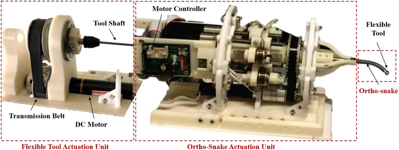
As shown in Fig. 3, the ortho-snakes actuation unit has 4 motors (RE16, Maxon Motor Inc.) with spindle drives (GP16, Maxon Motor, Inc.) to pull the ortho-snakes cables and provide both C- and S-bend capabilities. Furthermore, another DC motor (RE16, GP16C, Maxon Motor Inc.) rotates the actuation unit about its central axis (roll DoF) for out-of-plane cutting and drilling capabilities. It also has four load cells (Model 31Mid, Honeywell Inc.) to read each of the cable tensions. This actuation unit provides a central channel for passing the tools through it and being rotated by the tool actuation unit mechanism comprising of a DC motor (EC 22, GP22C, Maxon Motor Inc.) and a transmission and gripping mechanism. A custom C++ interface performs independent velocity or position control of each motor of the ortho-snakes actuation unit.
Fig. 3.
The steerable drilling system. This system includes two main parts: (i) the ortho-snake and its actuation unit, which controls the bending direction and bending plane of the CM; (ii) the flexible drilling tool integrated within the ortho-snake and its actuation mechanism.
B. The Bendable Medical Screw
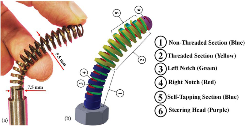
After making a curved tunnel using our steerable drilling system, we insert a passive BMS, which can safely morph and interact with the bone inside the tunnel and also generate sufficient fixation force for the bone fragments. Fig. 4 demonstrates the conceptual design and fabricated BMS and the following describes the technical specifications, which have been considered during the design and fabrication procedure.
Fig. 4.
The bendable medical screw: (a) designed and fabricated self-tapping BMS (OD = 9.5 mm); (b) Conceptual design of a BMS showingthe considered features to address the design requirements.
1). The BMS Notches Design:
It is worth noting that unlike rigid screws, the BMS axis of twist is not straight and varies based on the geometry of the drilled curved tunnel. Also, the twist axis of the tightening/loosening torque applied on the BMS head is not aligned with the BMS variable twist and translational axis. To remedy this, we have designed two arrays of orthogonal notches, marked by numbers ③ and ④ in Fig. 4 (shown in green and red colors), along the BMS shaft. The orthogonality of the notches guarantees that the BMS can morph inside a curved tunnel by freely bending in different planes and move forward when a torque is applied to its head. In addition, the notches geometry (i.e., shape, size, and number of threads) together with the outer diameter, core diameter, and pitch of the BMS (as shown by numbers ② and ④ in Fig. 4), the screw material, and the ultimate shear strength and density of the bone [14] determine the flexibility and internal fixation efficacy and strength of the screw. There is a trade-off between the screw flexibility and strength, which needs to be optimized prior to fabrication. As detailed in [8], this optimization can be performed through a finite element analysis simulating both flexibility and strength of the BMS in the presence of various boundary conditions.
2). Steerable Head:
To guarantee a safe interaction between the tip of the screw and the bone, a round passive steering head has been designed for the screw (as marked by number ⑥ in Fig. 4).
3). Self-Tapping Section:
The screw self-tapping capability is a critical feature of the BMS. As shown in Fig. 4, ⑤shows the section considered for making threads while moving the screw inside the curved tunnel. Of note, the geometry of this section determines the depth and shape of the threads and subsequently the amount of the generated friction to bear an external load while fixating the bone fragments.
4). Fabrication Procedure:
Similar to ortho-snake, we fabricated the BMS from Nitinol (NiTi) due to its biocompatibility for medical use and its super-elasticity yet greater structural strength as compared to other materials (e.g., stainless steel). Due to the constrained dimensions dictated by ortho-snake and the cutting tool, we designed the BMS with a core diameter of 7.5 mm, outer diameter of 9.5 mm and overall length of 50 mm. Of note, these sizes can easily be adjusted depending on the surgical application in hand. To design the geometry of the threads (i.e., type, depth, and pitch), we analyzed the traditional medical cancellous and cortical bone screws and selected V-shape threads. These threads are typically used in rigid cancellous bone screws and result in a larger pitch(i.e., less number of threads in a given length) yet greater holding capacity in cancellous bone [14]. In addition, these threads ensure sufficient space for the orthogonal notches along the BMS shaft. To make the BMS sufficiently flexible, we created a through hole inside the BMS shaft (i.e., a cannulated BMS) and deep notches in the space between threads such that they intersected the through hole (Fig. 4). After performing rigorous Finite Element (FE) analysis in COMSOL Multiphysics (COMSOL AB, Stockholm, Sweden) detailed in [8], we designed our cannulated BMS with inner hole diameter of 5 mm and 11 V-shape threads with 3.175 mm pitch.
Fig. 4a shows the fabricated BMS from nitiniol based on the described design parameters. The fabrication procedure included a CNC machining to cut the threads, steering head, and the self-tapping edges on a 12 mm Nitinol rod (Kelloggs Research Lab, New Hampshire, USA) followed by drilling a 5 mm through hole inside the threaded rod. We finalized the process by cutting the orthogonal notches on the surface of the BMS using a wire-cut electrical discharge machine (EDM).
III. EVALUATION EXPERIMENTS AND RESULTS
A. Curved Drilling Experiments on Human Cadaveric Bones
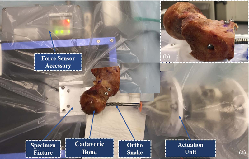
To perform these experiments, we obtained a human male femur specimen and cut samples from its medial epicondyle, shaft (body) as well as its head and neck. Fig. 5 demonstrates the experimental setup including the curved drilling system and two of the specimens mounted on the sample holder mechanism. of note, This mechanism consists of a brushless DC motor (RE16, Maxon Motor, Inc.) with a spindle drive (GP16, Maxon Motor, Inc.) that moves a cart carrying the sample on a linear stage. This mechanism is mounted in front of the tip of the drilling system and provides the sample a feeding velocity. For each experiment, we first mounted the specimen on the sample holder mechanism and inserted the flexible drill into the ortho-snake and cutting unit. We then set the ortho-snake’s plane of bend and locked the roll DoF of the actuation unit.
Fig. 5.
Experimental setup used to perform the curved drilling experiments on the cadaveric specimens.
To analyze various drilling possibilities and curvatures, we considered four different desired cable tensions (i.e., Tdes= 6, 20, 23, and 25 N). The maximum cable tension was limited by the 30 N maximum load capacity of the utilized stainless steel braided cable (8930T18, McMaster-Carr). In [6], we showed that the feeding velocity does not have a significant impact on the drilling curvature. However, it has a direct role on buckling and time of the drilling procedure. Our results showed that a 0.1 mm/s feeding velocity with a constant rotational speed of 2250 rpm lead to the fastest drilling procedure with negligible buckling in the ortho-snake and flexible tool. To control the cable tension during the experiments, in [6], we introduced the following control paradigm:
where V is the commanded motor velocity to pull the ortho-snake’s cable, T(t) is the measured cable tension by the load cell at each time instant, and Tdes is one of the mentioned desired cable tensions (i.e., 6, 20, 23, and 25 N). As described in [6], κ is a proportional constant for each Tdes ensuring an equal rising time response in each experiment.
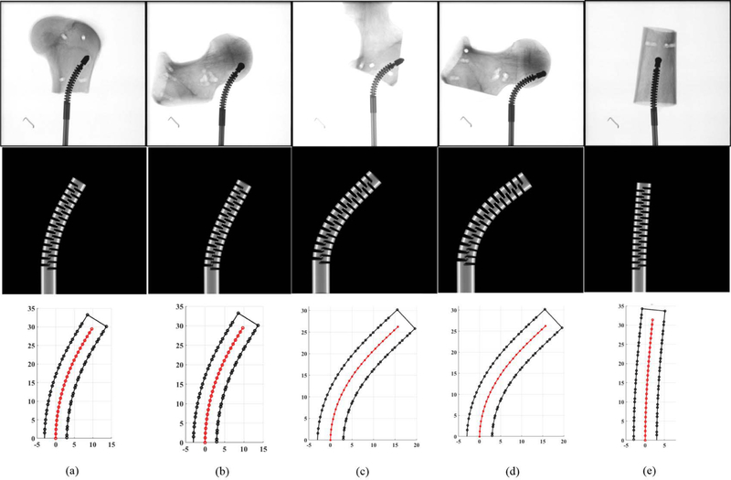
Fig. 6 summarizes the obtained results in these experiments. First row of these results demonstrates the X-ray images of the drilled tunnels on the five specimens—taken by C-arm machine (ARCADIS Orbic, Seiemens; Munich, Germany). To obtain the curvature of these tunnels and measure maximum displacement of the ortho-snake in each experiment, we implemented a 2D-3D registration method [15] to register the ortho-snake shape from the X-ray images, as shown in the second row of Fig. 6. In this method, an X-ray image is first converted to a black-and-gray image and then the position of the CDM base is obtained. Given the known kinematics model of ortho-snake [16], a 4-point cubic spline interpolation is used to compute the ortho-snake’s outline and its shape curve in each image. Details of this registration can be obtained in [6] and [15].
Fig. 6.
Results of curved drilling experiments on human cadaveric bones. First row demonstrates the X-ray images of the drilled tunnels. Second row shows the ortho-snake’s shapes obtained with the 2D-3D registration method. Third row demonstrates the results of the reconstructed drilling trajectories. Results of the experiments performed with (a) 0.10 mm/s feed-velocity and 20 N pulling tensions; (b) 0.10 mm/s feed-velocity and 20 N pulling tensions; (c) 0.10 mm/s feed-velocity and 25 N pulling tensions; (d) 0.10 mm/s feed-velocity and 25N pulling tensions; (e) 0.05 mm/s feed-velocity and 6 N pulling tensions.
The last row of Fig. 6 demonstrates the results of the reconstructed drilling trajectories. The center-line of the drilled tunnel as well as the border of the ortho-snake has been shown to better demonstrate the generated curved tunnel. In Fig. 6, each column of figures corresponds to a particular experiments performed by a set of cutting parameters. As shown, the maximum displacement (i.e., 16 mm) corresponds to the 25 N cable tension while a 2 mm displacement resulted in due to a 5 N cable tension. Additionally, comparison of Fig. 6a with Fig. 6b and Fig. 6c with Fig. 6d confirm the repeatability of the experimental results performed with identical cutting parameters. As it can be observed, despite using different cadaveric specimens with distinct geometries, the resulted drilled tunnel is identical.
B. Case Study: Internal Fixation of Femoral Neck Fractures With Osteoporosis
Femoral neck fractures is one of the most common and increasing traumatic injuries in the elderly patients [10]. Cannulated screws are often used for fixation of these fractures, however, almost half of these surgeries have poor results due to the unstable fixation, and poor-quality of the osteoporotic bone [17]. To mitigate this issue, several screw placement configurations such as the central screw placement of the distal screw [18] and the inverted triangle configuration [19] have been developed and suggested in the literature. In these methods, typically three parallel cannulated rigid screws are utilized. These methods, however, do not always guarantee appropriate fixation strength for osteoporotic bones [10]. This is because (i) the initial interfragmentary compression of these configurations is often insufficient because of inserting these implants inside the osteoporotic regions; (ii) the screws become occasionally unstable since they are inserted close to each other in a confined space and limited options for insertion point (i.e., mainly greater trochanter). The lateral cortical support is, therefore, often compromised [10]. We propose the use of curved drilling technique and the BMS to provide surgeons with a degree of freedom in selecting the drilling entry point and avoid inserting the implant in the weak regions. In our approach, the surgeon can navigate the ortho-snake along a predefined curved trajectory to secure and anchor the BMS in a healthy region inside the femoral head. To evaluate and compare our suggested procedure, we performed the following preliminary FE simulations. Of note, in these simulations, we have only considered one screw for fixation of the femoral neck fracture, which may not be performed in a real surgical scenario. The main goal of these preliminary analysis, however, was the comparison of the performance of the BMS with a typical straight screw in the presence of normal gait load.
3D model Preparation:
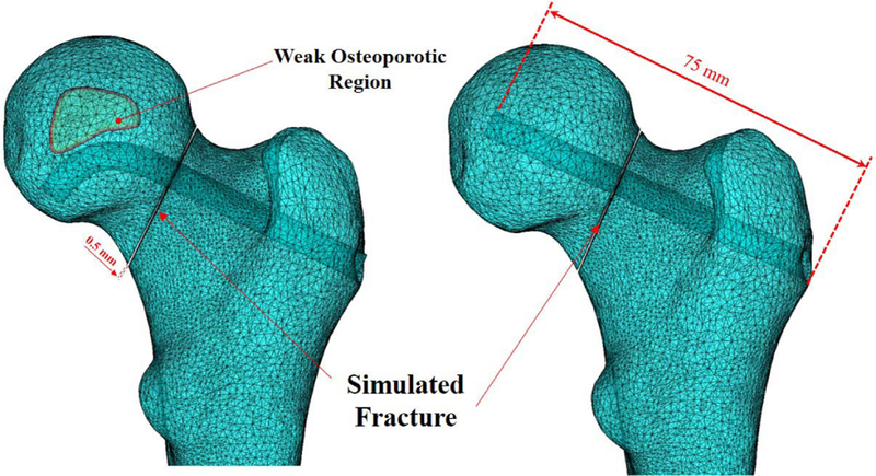
We first created a three-dimensional model of a femur from segmented computed tomography (CT) scan of a human cadaveric specimen. For this purpose, we specified the domains of the femur through a threshold-based segmentation of the bony anatomy and then manually improved the segmentation to smoothen the three-dimensional femur model with the use of image processing softwarei.e., Medical Imaging Interaction Toolkit (MITK) [20]. We then imported this model into SolidWorks (Dassault Systmes SolidWorks Corporation, MA, USA) software, to create an arbitrary fracture in the femoral neck with 0.5 mm width (Fig. 7). To compare the performance of fixation with the BMS straight rigid screw, we created two models with identical fracture geometry and arbitrary curved and straight tunnels with 75 mm length. Fig. 7 shows the geometry of these simulated tunnels together with an arbitrary-made osteoporotic region. As shown in this figure, the drilled tunnel has been designed such that it avoids the osteoporotic region and anchor the BMS in a healthy region.
Fig. 7.
3D meshed models of the considered femur comprised of curved and straight tunnels together with their identical fracture geometry. Left figure shows a conceptual curved drilling trajectory avoiding an osteoporotic region. This trajectory can be obtained by real-time control of the steerable drilling system.
FE Model:
The finite element model of the femur was generated using linear 10-node tetrahedral elements in COMSOL Multiphysics. The initial mesh was created based on the physics of the model such that the FE model has smaller size of elements (0.03 mm) at the interface and fracture zone. A mesh convergence analysis was then performed for both models containing BMS and straight screw. Using adaptive mesh refinement provided in COMSOL, we improved the mesh so that the L2 norm of error was minimized everywhere in the model. Using this method, the mesh is iteratively refined in regions where the error is estimated to be high and it is coarsened where a fine mesh is not needed. The final meshes of the BMS and Straight screw configurations contained 164173 and 140801 elements, respectively. Fig. 7 shows 3D models of two different screw configurations together with the arbitrary fracture and generated FE mesh.
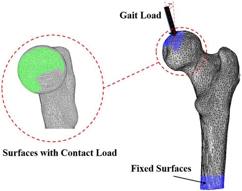
In our analysis, we assumed both curved and straight screws are made of Nitinol material. We also simplified geometries of the screw models as simple cylinders without threads. Cortical and cancellous femoral bone and Nitinol elements were assumed linear, elastic and isotropic with average Youngs modulus of 12 GPa, 600 MPa and 83 GPa, and Poissons ratios of 0.4, 0.29 and 0.33, respectively [7], [21]. The material properties of the bone were assigned so that the upper 50 mm region of the proximal femur to be mostly trabecular, and the remaining lower region to have 1 to 3 mm thickness of the cortical bone layer [22]. For this purpose, we identified the distance between triangular surfaces of the femur and centroids of the bone elements using closest neighbor and bounding spheres approach of the ICP algorithm [7]. For the lower region, the elements within 1 to 3 mm of the femoral bone surface were assigned as cortical and the remaining internal elements as trabecular. As shown by an arrow in Fig. 8, a load of 1421.8 N [‒ 182.77N,0−109.82N, 923.62N] was extracted from a patient data set (called “HSR” in [23]) during his/her normal walking. This load was distributed over the cartilaginous surface of the femur that is in contact within the hip joint [23]. A fixed boundary condition was also applied at the distal end of the femur (Fig. 8).
Fig. 8.
Fixed boundary and loading conditions (i.e., 1421.8 N [−182.77N, −109.82N, 923.62N]). The Gait Load arrow represent the real orientation of the force(s) acting on the femoral head.
FE Simulation Results:
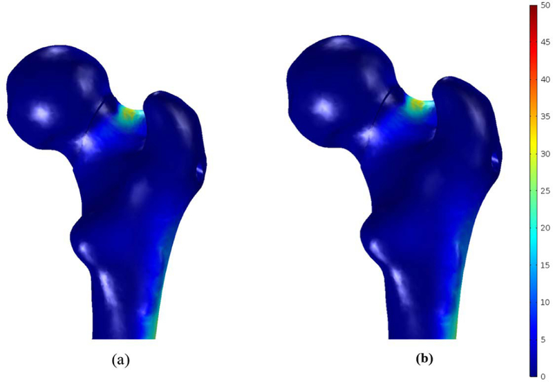
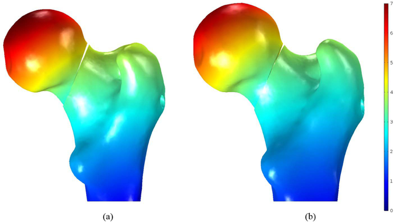
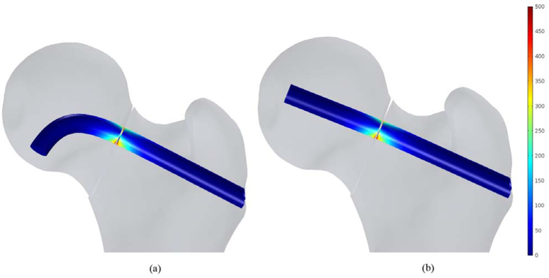
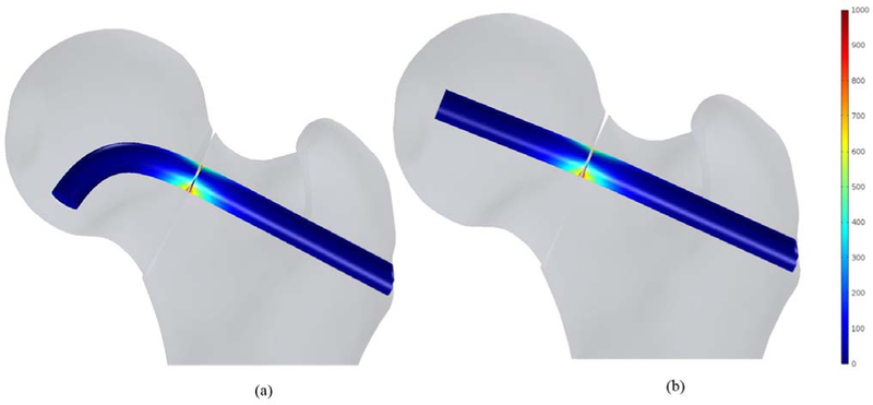
In this study, the bone failure criterion based on maximum principal stress was adopted. To account for tensile stress emerging in the subtrochanteric region during normal walking, maximum first principal stress of the femur was compared with σtult 110 MPa which is the tensile strength of cortical bone reported= in [7] and [21]. Typical tensile stress distribution was observed subject to gait loading for both models as shown in Fig. 9. The maximum first principal of the fixated femur with BMS at the superior domain of the neck was computed as 34.1 MPa, which is 31% of σtult; however, the peak value was 37.2 MPa for straight screw configuration, which reaches 34% of σtult. Therefore, the maximum principle stresses at neck were smaller than tensile strength σtult and the failure risk was estimated quite low for both models subject to gait load. Moreover, as expected, high stresses emerged nearby fracture region at the drilled area as well as distal regions of the subtrochanter. As shown in Fig. 10, displacement of the femoral bone for both models is similar with interfragmentry fracture displacement of 4.68 mm for the model contains the BMS and 4.41 mm for the straight screw configuration. Similar distribution of normal and shear stresses was observed at the interface of both models as shown in Figs. 11 and 12 with the peak values appearing at the fracture location. Peak normal and shear stresses for the femur fixated with BMS were 1069 and 553.7 MPa, respectively compared to 1006 MPa and 521.8 MPa for the straight screw configuration, which are close to each other. Considering the ultimate tensile strength (1900 MPa) of Nitinol, it is demonstrated that the BMS, similar to straight screw does not fail/break in the presence of gait load.
Fig. 9.
First principal stress distribution (MPa) in femoral bone containing(a) the BMS and (b) straight screw.
Fig. 10.
Resulted displacement in the fixated femoral bone (mm) with (a) the BMS and (b) straight screw.
Fig. 11.
Normal stress distribution (MPa) at the fracture location of the fixated bone with (a) the BMS and (b) Straight screw.
Fig. 12.
Shear stress distribution (MPa) at the fracture location of the fixated bone with (a) the BMS and (b) Straight screw.
IV. DISCUSSION AND CONCLUSION
We have presented a steerable drilling system comprised of a continuum manipulator together with an appropriate flexible drilling tool to provide surgeons with a degree of freedom in selecting the drilling entry point and navigation capability inside a bone with complex geometry. As a complement to this curved drilling technique, we also designed and fabricated a flexible implant that can passively bend into and self-tap the drilled tunnel. Using these devices, the surgeon can navigate the steerable drill along a predefined curved trajectory to secure and anchor the screw in a healthy region inside the femoral head. This capability addresses the problem of various orthopedic surgeries such as osteonecrosis of femoral head [6] and internal fixation of bones with complex anatomies [9], where making a straight tunnel and/or using a straight rigid screw may arise a lot of complications due to the osteoporosis [10].
We verified the performance of the curved drilling system on a set of cadaveric specimens. As a complement and extension of our previous study in [6] performed on polyurethane samples simulating human cancellous bones, the results of the current study demonstrated the capability and repeatability of the developed system in drilling human cadaveric bones with various curvatures. Although we generally characterized the behavior of the presented system on cadaveric specimens, the results are also extendable to real-case surgical scenarios. In future, we will utilize the insight obtained in this study to plan and control the ortho-snake to drill curved tunnels for various orthopedic applications including treatment of osteonecrosis [7] and bone augmentation of the hip (i.e., femoroplasty) to prevent osteoporotic fractures [24]. We will also extend our drilling capability in cadaveric specimens to create S-shape tunnels utilizing both actuation tendons of the ortho-snake as described in [6].
In our finite element analysis, we considered an arbitrary fracture in the femoral neck and characterized the behavior and fixation capability with one curved screw versus a typical rigid screw in the presence of gait load. In this preliminary FE simulation, our goal was to compare the displacement and stress distribution of the fracture together with the femoral bone in these two fixation models. The presented results in Section III demonstrated that the use of curved screw not only does not deteriorate the fixation strength of a fractured region, but it also provides surgeons with the aforementioned accessibility and steerability benefits. The BMS and the straight screw underwent almost identical peak normal and shear stresses at the interface located at fracture area (both stresses were 6% higher in the BMS model). Also, both simulated models had almost similar fracture displacements (4.61 mm versus 4.41 mm). It is worth re-emphasizing that although in the performed FE analysis, we did not model the osteoporotic region, the simulation results convey that using the BMS for an osteoporotic bone may dramatically improve the biomechanical performance of fixation compared to a straight screw. In other words, by real-time control of the steerable drilling system and drilling a curved tunnel in less-weaken regions of the osteoporortic bone, using BMS in this tunnel may lead to a similar biomechanical behavior as compared to utilizing a rigid straight screw in a healthy bone. Furthermore, inserting a rigid screw inside osteoporotic region may not generate a necessary interfragmentary compression and, thereby leading to an unstable fixation and failure as has been discussed in [10].
In the future, additional FE simulations and experiments are needed to verify the internal fixation capability of our proposed method for more diverse situations including geometry of the fractured bones, location of the eccentric load, curvature of the drilled tunnel and etc. In addition, thorough and rigorous biomechanical studies are needed to determine the minimum number of the BMS as well as their optimized trajectories to generate an adequate fixation capability for an osteoporotic bone. Aside from the biomechanical analysis, we will also include more cadaveric experiments to further compare the results of simulations with experimental data. We also plan to investigate the performance of a reinforced BMS with artificial bone grafts for various orthopedic applications [7]. As mentioned, our proposed steerable drilling system can help surgeons to avoid drilling inaccurate tunnels particularly in the weak regions of the osteoporotic bone. In this paper, we focused on the feasibility of using the steerable drilling system on a human cadaveric bone, in the future, we plan to investigate this capability in a realistic clinical setting by developing real-time steering control paradigms using the embedded FBG sensing units and/or intermittent X-ray imaging feedback.
Acknowledgments
This work was supported by NIH/NIBIB under Grant R01EB016703.
Contributor Information
Farshid Alambeigi, Laboratory for Computational Sensing and Robotics, The Johns Hopkins University, Baltimore, MD 21218 USA..
Mahsan Bakhtiarinejad, Laboratory for Computational Sensing and Robotics, The Johns Hopkins University, Baltimore, MD 21218 USA..
Shahriar Sefati, Laboratory for Computational Sensing and Robotics, The Johns Hopkins University, Baltimore, MD 21218 USA..
Rachel Hegeman, Laboratory for Computational Sensing and Robotics, The Johns Hopkins University, Baltimore, MD 21218 USA, and also with the Applied Physics Laboratory, The Johns Hopkins University, Laurel, MD 20723 USA..
Iulian Iordachita, Laboratory for Computational Sensing and Robotics, The Johns Hopkins University, Baltimore, MD 21218 USA..
Harpal Khanuja, Department of Orthopedic Surgery, The Johns Hopkins Medical School, Baltimore, MD 21205 USA..
Mehran Armand, Laboratory for Computational Sensing and Robotics, The Johns Hopkins University, Baltimore, MD 21218 USA, and also with the Applied Physics Laboratory, The Johns Hopkins University, Laurel, MD 20723 USA..
REFERENCES
- [1].Vitiello V, Lee S-L, Cundy TP, and Yang G-Z, “Emerging robotic platforms for minimally invasive surgery,” IEEE Rev. Biomed. Eng, vol. 6, pp. 111–126, 2013. [DOI] [PubMed] [Google Scholar]
- [2].Gosline AH et al. , “Percutaneous intracardiac beating-heart surgery using metal MEMS tissue approximation tools,” Int. J. Robot. Res, vol. 31, no. 9, pp. 1081–1093, 2012. [DOI] [PMC free article] [PubMed] [Google Scholar]
- [3].Cöemert S et al. , “Integration of a snake-like dexterous manipulator for head and neck surgery with the da vinci research kit,” in Proc. Hamlyn Symp. Med. Robot, 2016, pp. 58–59. [Google Scholar]
- [4].Burgner J et al. , “A telerobotic system for transnasal surgery,” IEEE/ASME Trans. Mechatronics, vol. 19, no. 3, pp. 996–1006, Jun. 2014. [DOI] [PMC free article] [PubMed] [Google Scholar]
- [5].Alambeigi F, Wang Y, Murphy RJ, Iordachita I, and Armand M, “Toward robot-assisted hard osteolytic lesion treatment using a continuum manipulator,” in Proc. 38th Annu. IEEE Int. Conf. Eng. Med. Biol. Soc. (EMBC), 2016, pp. 5103–5106. [DOI] [PubMed] [Google Scholar]
- [6].Alambeigi F et al. , “A curved-drilling approach in core decompression of the femoral head osteonecrosis using a continuum manipulator,” IEEE Robot. Autom. Lett, vol. 2, no. 3, pp. 1480–1487, Jul. 2017. [Google Scholar]
- [7].Bakhtiarinejad M et al. , “A biomechanical study on the use of curved drilling technique for treatment of osteonecrosis of femoral head,” in Computational Biomechanics for Medicine 2018. Cham, Switzerland: Springer, 2019. [Google Scholar]
- [8].Alambeigi F et al. , “Inroads toward robot-assisted internal fixation of bone fractures using a bendable medical screw and the curved drilling technique,” in Proc. 7th IEEE Int. Conf. Biomed. Robot. Biomechatron. (Biorob), 2018, pp. 595–600. [DOI] [PMC free article] [PubMed] [Google Scholar]
- [9].Foley WL, Frost DE, Paulin WB, and Tucker MR, “Internal screw fixation: Comparison of placement pattern and rigidity,” J. Oral Maxillofacial Surgery, vol. 47, no. 7, pp. 720–723, 1989. [DOI] [PubMed] [Google Scholar]
- [10].Filipov O and Gueorguiev B, “Unique stability of femoral neck fractures treated with the novel biplane double-supported screw fixation method: A biomechanical cadaver study,” Injury, vol. 46, no. 2, pp. 218–226, 2015. [DOI] [PubMed] [Google Scholar]
- [11].Wilkening P, Alambeigi F, Murphy RJ, Taylor RH, and Armand M, “Development and experimental evaluation of concurrent control of a robotic arm and continuum manipulator for osteolytic lesion treatment,” IEEE Robot. Autom. Lett, vol. 2, no. 3, pp. 1625–1631, Jul. 2017. [DOI] [PMC free article] [PubMed] [Google Scholar]
- [12].Sefati S et al. , “A highly sensitive fiber Bragg grating shape sensor for continuum manipulators with large deflections,” in Proc. IEEE SENSORS, 2017, pp. 1–3.29780437 [Google Scholar]
- [13].Alambeigi F, Murphy RJ, Basafa E, Taylor RH, and Armand M, “Control of the coupled motion of a 6 DoF robotic arm and a continuum manipulator for the treatment of pelvis osteolysis,” in Proc. 36th Annu. IEEE Int. Conf. Eng. Med. Biol. Soc. (EMBC), 2014, pp. 6521–6525. [DOI] [PMC free article] [PubMed] [Google Scholar]
- [14].Wang T, Boone C, Behn AW, Ledesma JB, and Bishop JA, “Cancellous screws are biomechanically superior to cortical screws in metaphyseal bone,” Orthopedics, vol. 39, no. 5, pp. e828–e832, 2016. [DOI] [PubMed] [Google Scholar]
- [15].Otake Y, Murphy RJ, Kutzer MD, Taylor RH, and Armand M, “Piecewise-rigid 2D-3D registration for pose estimation of snake-like manipulator using an intraoperative X-ray projection,” Proc. SPIE, vol. 9036, pp. 9036–9036-6, 2014, doi: 10.1117/12.2043242. [DOI] [Google Scholar]
- [16].Murphy RJ, Kutzer MD, Segreti SM, Lucas BC, and Armand M, “Design and kinematic characterization of a surgical manipulator with a focus on treating osteolysis,” Robotica, vol. 32, no. 6, pp. 835–850, 2014. [Google Scholar]
- [17].Gjertsen J-E et al. , “Internal screw fixation compared with bipolar hemiarthroplasty for treatment of displaced femoral neck fractures in elderly patients,” J. Bone Joint Surgery, vol. 92, no. 3, pp. 619–628, 2010. [DOI] [PubMed] [Google Scholar]
- [18].Thiele OC, Eckhardt C, Linke B, Schneider E, and Lill CA, “Factors affecting the stability of screws in human cortical osteoporotic bone: A cadaver study,” J. Bone Joint Surgery Brit, vol. 89, no. 5, pp. 701–705, 2007. [DOI] [PubMed] [Google Scholar]
- [19].Mizrahi J, Hurlin RS, Taylor JK, and Solomon L, “Investigation of load transfer and optimum pin configuration in the internal fixation, by muller screws, of fractured femoral necks,” Med. Biol. Eng. Comput, vol. 18, no. 3, pp. 319–325, 1980. [DOI] [PubMed] [Google Scholar]
- [20].Wolf I et al. , “The medical imaging interaction toolkit,” Med. Image Anal, vol. 9, no. 6, pp. 594–604, 2005. [DOI] [PubMed] [Google Scholar]
- [21].Lutz A, Nackenhorst U, von Lewinski G, Windhagen H, and Floerkemeier T, “Numerical studies on alternative therapies for femoral head necrosis,” Biomech. Model. Mechanobiol, vol. 10, no. 5, pp. 627–640, 2011. [DOI] [PubMed] [Google Scholar]
- [22].Koivumäki JE et al. , “Ct-based finite element models can be used to estimate experimentally measured failure loads in the proximal femur,” Bone, vol. 50, no. 4, pp. 824–829, 2012. [DOI] [PubMed] [Google Scholar]
- [23].Bergmann G et al. , “Hip contact forces and gait patterns from routine activities,” J. Biomech, vol. 34, no. 7, pp. 859–871, 2001. [DOI] [PubMed] [Google Scholar]
- [24].Basafa E et al. , “Patient-specific finite element modeling for femoral bone augmentation,” Med. Eng. Phys, vol. 35, no. 6, pp. 860–865, 2013. [DOI] [PMC free article] [PubMed] [Google Scholar]


