Abstract
In this study, a priority-aware lightweight secure sensing model for body area networks with clinical healthcare applications in internet of things is proposed. In this model, patients’ data is labeled according to the proposed prioritizing mechanism. This provides a prioritized and delay-less service in the server side for the patients with critical conditions. In the proposed model, the sensed data is monitored in a real time way to calculate its sparsity level. Then, the ,calculated sparsity level is used to determine the number of required measurements for data sampling. This allows to sample the data with the number of measurements proportional to the sparsity level and information content of the data. Moreover, the particular design of the measurement matrix causes the aggregated data to be encrypted and its security be guaranteed. Simulation results show that compared to its counterpart schemes, the proposed sensing model not only provides security but also reduces the average energy consumption of the sensor nodes and the average packet delivery delay. This improvement originates from the reduction of the number of required bits for transferring the sensed data and is due to the consideration of the information content and sparsity level variation in the sensed data.
Keywords: Internet of Things, Body area networks, Lightweight secure sensing, Energy, Delay
1. Introduction
With rapid development of the technology, more sensor devices are available and Internet of Things (IoT) has been raised as the first and most significant subject of network technology. IoT can be used for self-organized fast operations at any time and location around the world and has led to a consistent improvement for applied programs including Body Area Networks.
BANs, as a special type of Wireless Sensor Networks (WSNs), has attracted the attention of the researchers due to their potential value. BANs include several tiny sensor devices, which are mounted on or inside the body [1]. These networks have been designed to continuously transfer the identified body-related data and act as a key healthcare infrastructure for remote monitoring and treatment.
Accurate statistics predict that the number of senior people aged beyond 65 will be around 70 million in 2025 [2]. Since this elderly population needs more health services and care management, the development of BANs facilitates monitoring of the elderly people in society. On the other hand, due to the spread of acute and chronic diseases in different societies, public health monitoring is among the most important health problems. This is where that BANs come to play and can be used to control different diseases such as diabetes, neoplasms, asthma, Parkinson’s, heart diseases and, strokes, which are the deadliest risk factors in today’s societies [3], [4]. BANs enable control and monitoring of different diseases and obviation of the need to medical staff and equipment using the real time remote control and monitoring. Therefore, proper management of the existing issues and challenges in BANs is necessary due to importance of patients’ health.
Security and energy consumption are among the issues and challenges of the BANs, which require proper management [5], [6], [7], [8]. These issues can be resolved by improving the security weaknesses of the wireless networks, on which the main clinical healthcare programs rely. Design of logical routings between the sensors used in these networks, improvement of the efficiency, and optimization of the consumed energy can also help to obviate the mentioned issues. Routing plays a vital role in connecting the scattered nodes, creating paths, and realizing on-time and reliable data transmission in BANs. Therefore to maximize the energy efficiency of a single node, energy efficiency and stability issues should be considered in the design of routing protocols. Various routing algorithms have been proposed for BANs [9], which can be classified into six general categories: (a) quality of service-based routing, (b) postural movement-based routing, (c) temperature-based routing, (d) cluster-based routing, (e) cross-layered routing, and (f) position-based routing. The flowchart of Fig. 1 shows this classification. In Section 2, we review some of the routing algorithms, which are more relevant to this research work, as highlighted in the flowchart of Fig. 1.
Fig. 1.
A flowchart representing the classification of the routing protocols proposed in the surveyed papers.
2. Related works
As shown in flowchart of Fig. 1, the focus of attention in the literature review of the present study is on network routing protocols of body area networks, medical applications, and in more detail remote medicine and chronic disease monitoring. To increase the accuracy and efficiency of the study, other areas have been excluded. Also, since one of the challenges and factors affecting the efficiency of body area networks is the amount of energy consumption and the latest researches have used clustering technique to solve this problem, in the section on chronic disease monitoring, there has been more emphasis to review the presented routing articles based on clustering. The main goal was to evaluate and compare them with each other, so that we can use the best work presented as a basis for evaluating the amount of energy consumption in the proposal. Later, we will examine these algorithms in detail.
An energy-efficient temperature-aware routing protocol, named Mobility Supporting Adaptive Threshold-based Thermal-Aware (M-ATTEMPT), has been proposed in [10]. The protocol offers mobility support capability for body heterogeneous WSNs. In the protocol, each node knows the information of other nodes and the sink node, and sends its data over the path with the lower number of hops and less energy consumption. In critical conditions, the protocol suspends all of the processes and sends the critical data directly to the sink node. The protocol identifies the Hot-spot and routes the data away from its corresponding links. The sink node schedules communications using a time-division multiple-access scheme. The performance of the M-ATTEMPT protocol is compared with ATTEMPT protocol in terms of network lifetime, successful packet delivery, and power efficiency by simulations conducted in MATLAB. Simulation results show that M-ATTEMPT improves the network lifetime and successful packet delivery by 29.5% and 12.55, respectively, compared to its ATTEMPT counterpart.
A link-aware and energy-efficient scheme for BANs, abbreviated as LAEEBA, is presented in [11], which includes four stages of initialization, next-hop selection, routing, and path-loss selection. The scheme chooses the paths with minimum hops to transfer data, where critical and normal data are delivered by single-hop direct and multi-hop indirect communications, respectively. In the scheme, the nodes with minimum energy and minimum distance from the sink node are selected as forwarder nodes, which aggregates data and sends it to the sink node. The performance of the proposed scheme is evaluated in comparison to the Destination Assisted Routing Enhancement (DARE) protocol with the help of MATLAB simulations. Simulation results show that the LAEEBA algorithm outperforms the DARE scheme by providing a lower energy consumption and packet delivery delay.
A routing protocol named Ant Colony Optimization BAN (ACOBAN) has been proposed in [12], which selects an optimal path to deliver the monitoring data of patients’ vital signs such that network lifetime and load balancing improve. To determine the optimal path, the protocol uses a combination of the ant colony algorithm and clustering. In ACOBAN protocol, the cluster head is dynamically selected in each round of the algorithm using the breadth-first search algorithm. The protocol is simulated in OMNet++ simulator and its performance parameters such as end-to-end delay, energy consumption, and power efficiency are compared to the ZKBAN algorithm. The results demonstrate that ACOBAN provides a better power efficiency, end-to-end delay, and power consumption than the ZKBAN algorithm.
In [13], an Energy-Efficient Routing Protocol (EERPF) for wireless body area sensor networks has been introduced, where two sensor nodes are used to sense critical data and send it directly to the sink node. To save energy consumption, other nodes send their data by an indirect multi-hop communication through a forwarder node, which is selected according to the maximum residual energy and minimum distance from the sink node. Considering the parameters of the number of dead nodes, the number of received packets in the sink node, and the amount of residual energy versus round progress, EEPRF protocol was compared with M-ATTEMPT by MATLAB simulations. The results showed that EEPRF has a longer network lifetime and is more stable. Moreover, the number of received packets in the sink node is more in comparison with M-ATTEMPT because in EEPRF, the lifetime of the nodes is longer in higher rounds and consequently, more sensor nodes are available. Unlike the M-ATTEMPT, where the sensor nodes consume much energy and die sooner, EEPRF is more energy-optimal and stable. The security is not considered in the EEPRF protocol, which is a weakness for this protocol with applications in body area wireless networks.
A Clustering-based Routing Protocol for wireless Body Area network (CRPBA) has been proposed in [14], which targets minimization and maximization of the energy consumption and network lifetime, respectively. In CRPBA, depending on the type of information, data is transferred directly to the base station, or the clustering technique is used to transfer data to the base station through a gateway body sensor. Two sink nodes attached at the back and neck of the patient are used for aggregation and transmission of the indirect and direct data, respectively. Moreover, the cluster head is dynamically chosen in each run round of the CRPBA algorithm with the metrics of maximum residual energy and minimum distance to the base station. Considering the performance indicators of the number of dead nodes and residual energy, MATLAB simulations are employed to compare the performance of the CRPBA to a scenario, where the CRPBA is not used. As simulation results show, the clustering-based CRPBA routing protocol improves the network quality by minimizing the consumed power and enhancing the stability period. Despite the obtained network quality, security issues, as a potential improving factor, are not considered in CRPBA protocol.
In [15], an energy-efficient clustering scheme (EECS) has been proposed for routing in Body Area Wireless Sensor Networks (BAWSNs) with a mobile sink node. In the scheme, a node can be in one of the states of cluster head, cluster member, or idle, where a Markov model is employed to identify node roles and estimate the transition from one state to another state. Since the sink node is mobile, the clustering depends on the location of the sink node, where the mobility of the sink is realized using a random mobility model to model the location and movement of the sink node. The cluster is dynamically selected according to a cost function such that the node with minimum energy cost function and maximum ability of data transmission is chosen as the cluster head. MATLAB simulation is used to evaluate the performance of the EECS in terms of the network lifetime and power efficiency compared to Gateway-based Energy-Aware multi-hop Routing (M-GEAR) and Modified Low-Energy Adaptive Clustering Hierarchy (MOD-LEACH) protocols. The results specify that the EECS algorithm outperforms the two other counterparts.
The authors of [16] have designed an Optimal Energy consumption routing based on Artificial Bee Colony (OEABC) for BAWSNs, where the bee colony algorithm is employed to select an energy-optimal path by considering factors such as residual energy of nodes, the importance level of nodes, path cost and path energy difference ratios. The energy consumption and convergence speed of the OEABC scheme are compared with those of genetic and ant colony algorithms using MATLAB simulations. The results report a less energy consumption and a higher convergence speed for OEABC in comparison with its two other counterparts. However, the OEABC scheme has a bit more delay than the other routing protocols because it uses an artificial intelligence-based algorithm.
To increase network lifetime and power efficiency, the authors in [17] have proposed a routing algorithm titled Dual Sink approach using Clustering Body area network (DSCB). Two sink nodes, as fixed cluster heads, are employed in DSCB to aggregate the received data from the sensor nodes and transfer it to the nearest gateway. In the protocol, data is sent directly or is transmitted indirectly through a forwarder node, which is selected based on minimum nodal distance from the sink, maximum residual energy, and maximum transmission power. Various performance metrics such as residual energy, power efficiency, and end-to-end delay are measured for the DSCB scheme to compare its performance with DARE and Improved Sable Increased-throughput Multi-hop Link-Efficient (IM-SIMPLE) routing protocols. MATLAB simulations show that the DSCB scheme provides better network stability, network lifetime, power efficiency, and end-to-end delay and outperforms the two other schemes. Again, despite the improvement in power consumption, security and privacy issues are not addressed by the DSCB method.
In [18], a routing protocol, named Traffic Priority Based Delay Aware and Energy Efficient Path Allocation Routing Protocol (Trip-EEC) is proposed for BAN applications, where traffic priorities are used for path assignment. In this protocol, the nodes with minimum temperature rise and maximum residual energy constitute the routes. In Tripe-EEC protocol, a three-fold mechanism is employed to identify the priority level of the sensed data, to classify patient’s data, and to use independent routing algorithm for normal and on-demand data. To assist the allocation of paths on the priority basis and avoid congestion, patient’s data is classified into four classes of normal data, on-demand data, emergency data of low threshold readings, and emergency data of high threshold readings. Compared to Energy-Efficient Routing Protocol (EERP), Trip-EEC provides a better power efficiency, average power consumption in sensor nodes, and packet delivery delay, as demonstrated by MATLAB simulations.
Table 1 summarizes the comparison of the surveyed routing protocols in terms of the critical and vital parameters, for designing any routing protocols in BANs IoT applications.
Table 1.
Performance comparison for the surveyed routing algorithms in BANs. See [10], [11], [12], [13], [14], [15], [16], [17], [18].
 |
Since healthcare data has critical nature and must be transferred without any delay and distortion, the researchers have proposed different routing protocols and techniques to enable the fast and efficient transmission of data. In this research, we have briefly surveyed the main routing protocols to have a better perspective over the subject and propose a protocol, where all the parameters required for an efficient routing for BANs are considered and covered.
As can be seen in Table 1, 78.6% of the investigated articles use mathematical-based methods and Nyquist sampling technique. The remaining 21.4% employs evolutionary algorithms and bio computations as well as Nyquist sampling method for data sampling. An important point that should be considered is that the evolutionary algorithms and bio computations consume much energy in addition to taking a long time. Therefore, they are suitable for the scenarios, where not only we encounter a huge volume of data but also the required equipment for heavy processing is available. In a scalable problem such as routing in BANs, where the processing and memory are limited, it is not common to use evolutionary algorithms and bio computations. They are only recommended when the data is processed in the cloud and the result of the process is exploited.
Another important fact that can be derived from Table 1 is that all the reviewed routing protocols use the Nyquist sampling, where the data is sampled without any attention to its information content. Considering the energy consumption as an important and vital parameter in these protocols, many redundant and unneeded bits are transferred during the transmission of the sensed data. This results in non-optimum energy consumption in each sensor and the whole network. This issue requires further investigation. On the other hand, despite the sensitive and vital nature of the data, security and privacy issues are not considered in the proposed routing protocols. This problem is a challenging hinder for the application of these protocols in IoT-based healthcare systems.
3. Problem definition
As mentioned before, conventional routing protocols use Nyquist sampling, where the sensed data is sampled with a sampling rate more than twice the highest frequency component of the data, without any attention to its information content, to recover the original data signal from its sampled discrete-time equivalent signal. This causes many redundant and unnecessary bits to be transmitted, which in turn not only increases end-to-end delay, bandwidth, and energy consumption but also reduces network lifetime and network reliability. Therefore, if the sensed data can be dynamically sampled according to its information content and sparsity level, a lower number of bits are required to transfer useful information content, which in turn reduces end-to-end delay and energy consumption, improves network lifetime and network reliability, and leads to optimal resource utilization.
4. System model
In this section, we introduce the system model and describe its constituting parts including the network topology and radio model, which are used for analyzing the proposed scheme.
4.1. Network topology
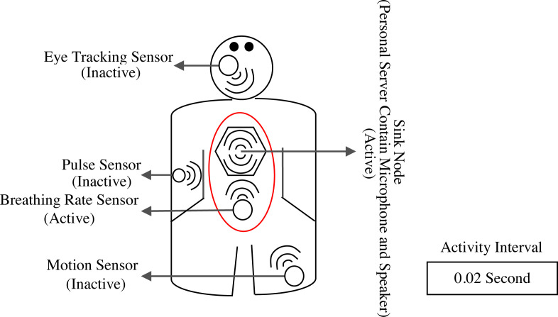
To investigate the impact of the proposed sensing model on security improvement and efficiency enhancement of the BANs, a simple network topology is introduced, on which the performance of the proposed scheme is evaluated. In this topology, four sensor nodes are used to monitor body physiological data while a single sink node is employed to monitor, aggregate, and prioritize the data sensed by the sensor nodes. The sensor nodes have the same computational power, are equipped with 0.3 Joule initial energy, are fixed at particular locations of the body, and transfer their data to the sink node using a single-hop direct communication. The sink node is located at the back, the central part of the body, includes much energy sources and computational power compared to other sensor nodes, and has dynamic access to the information of the sensor nodes including the amount of residual energy, identity, location, and the distance from the sink nodes. Fig. 2 displays the described topology.
Fig. 2.
Network topology in the proposed scheme.
Moreover, Table 2 shows the description and location of the nodes.
Table 2.
Node types and their locations in the described network topology.
| Node number | Description | Width coordinate (m) | Length coordinate (m) |
|---|---|---|---|
| 1 | Eye tracking sensor | 0.35 | 1.65 |
| 2 | Pulse sensor | 0.1 | 0.8 |
| 3 | Breathing rate sensor | 0.4 | 0.5 |
| 4 | Motion sensor | 0.7 | 0.1 |
| 5 | Sink node | 0.4 | 1 |
4.2. Radio model
The radio model describes the amount of energy consumed by electronic systems of the sensor nodes and sink node in the patient’s body. In our proposed scheme, we use the first-order radio model and single-chip low-power transceiver of Nordic nRF 2401A, which consumes less power than Chipcon CC2420 transceiver. The used transceiver works over 2.4 GHz bandwidth and its radio parameters are given in Table 3.
Table 3.
Radio parameters of Nordic nRF 2401A transceiver used in the proposed sensing model.
| Parameter | Value |
|---|---|
| DC current (TX) | 10.5 mA |
| DC current (RX) | 18 mA |
| Supply voltage (Min) | 1.9 V |
| 16.7 nj/bit | |
| 36.1 nj/bit | |
| 1.97 nj/bit | |
| 3.20 dB |
In this model, the energy consumption of the transceiver of each sensor implanted in the body of a male patient with 182 cm height, 70 kg weight, 79 cm waist circumference, and 3.20 dB Body Path Loss (BPL), and located with a distance from another sensor or sink node for transmuting and receiving K data bits in a single-hop communication is given by Eqs. (1), (2) [19], [20]
| (1) |
where is the amount of consumed power for transmitting data bits through a single-hop communication from th transmitter sensor to a receiver located in distance in a body transfer medium with an energy loss coefficient of . Moreover, denotes the power consumption of the electronic circuit of th sensor for transmitting one bit while is the power consumed by the amplifier circuit of th sensor for transmitting one bit.
| (2) |
where denotes the power consumption of the receiver of th sensor for receiving data bits from the transmitter via a single-hop direct communication. Further, is the power consumed by the electronic circuit of the receiver of th sensor for receiving one bit. Noting Eqs. (1), (2), the power consumption in each sensor node and the whole network is obtained by
| (3) |
| (4) |
Here, is the distance between the sensor and sink nodes given by
| (5) |
where and are the width coordinate of the source and destination nodes, respectively, and and denote length coordinate of the source and destination nodes, respectively.
5. Proposed scheme
To provide a solution for the problem defined in Section 3, a priority-aware lightweight secure sensing model for BANs is proposed. Fig. 3 shows the flowchart of the proposed scheme, where its different steps are described in the next subsections.
Fig. 3.
Flowchart of the proposed sensing model.
5.1. Generation and distribution of the activity intervals
In this step, the sink node, which includes more resources (energy, memory, transmission power, etc.) compared to the sensor nodes, creates, distributes, and assigns the activity intervals to the sensor nodes. The activity intervals are similarly assigned to the sensor nodes using Interleave Division Multiple Access (IDMA) protocol [21]. The IDMA is an advanced version of the Code Division Multiple Access (CDMA) protocol, which uses interleave technique to distinguish users rather than signature codes used in CDMA systems. The IDMA protocol provides advantages such as interference cancellation, diversity enhancement against fading, low-cost receiver, decentralized control, and optimum capacity. Fig. 4 describes the mechanism of interval creation and assignment.
Fig. 4.
Mechanism of activity interval creation and assignment in the proposed scheme.
As it can be observed in Fig. 4, the sensed data by the sensor node No. three are segmented according to the interleaver length of sensor node No. three; moreover, they are reordered through the presented sequence by it. In the mentioned sequence, the first to fifth places of the first division is respectively assigned to the fifth, first, third, second, and fourth place; additionally, the first to fifth places of the second division are respectively located at the fifth, first, third, second and fourth place. Ultimately, the achieved result of the stated procedure is sent to the sink node through the common channel.
5.2. Reception of the activity interval and waiting to start it
In this step, after reception of the activity interval, each node switches to sleep state until it starts the activity interval and data sensing, as shown in Fig. 5.
Fig. 5.
Data transmission from sensor to sink node in the activity interval in the proposed scheme.
5.3. Data sense and the calculation of sparsity level of the sensed data
In this step, when the activity interval starts, the sensor node switches from sleep to active state and continuously computes the sparsity level of the sensed data by Eq. (6) [22].
| (6) |
where is the sparsity level of the sensed data, is the squared one-norm of the sensed data vector , which is the summation of the absolute value of the elements of , and is the squared two-norm of , which is obtained by the Euclidean norm equation.
5.4. Determination of the compression ratio
Obtaining up-to-date information about the sensed data helps to tune and select the optimum value of the compression ratio. so, according to Eq. (7) when the sparsity level changes, equal or more than 50%, the sensor node uses the number of calculated measurements to update the compression ratio [23]. When the sparsity level changes less than 50% and has no considerable time variation, the default compression ratio is used. Here, the number of accomplished measurements which defines the compression ratio relates to the sparsity level through.
| (7) |
Where is the compression ratio, is the default compression ratio, is the changes in the level of the sensed data sparsity, is the number of measurements, is the number of samples and is a constant, whose value is set to 2 for a Gaussian measurement matrix.
5.5. Lightweight and secure sensing and the transfer of sensed data to the sink node
Being an information theory, lightweight and secure sensing provide a way to safely retrieve a sparse signal at a large scale from a small number of measurements. Lightweight and secure sensing can be expressed using Eq. (8). In lightweight and secure sensing, unlike the conventional method, where the sensed data are sampled, the data are measured. The measurement is in fact a linear combination of several samples. In the secure lightweight sensing step, a linear transform is used to map the data to a space, where the data is sparse. Then, the significant information of the data is sensed and the remaining useless information is ignored. Here, the data is sampled with a rate proportional to its information content, rather than sampling with Nyquist rate. Therefore, the number of required measurements to recover the data is considerably less than that of the Nyquist-based conventional methods [24].
| (8) |
Where is the measurement vector, is the measurement matrix and is the sensed data vector.
In addition, considering special conditions in the design of the measurement matrix and intelligently selecting the elements of the measurement matrix at this step will both improve the measurement and feasibility of data recovery and secure the sensed data. Here, for confidentiality of the sensed data and reduction of the total number of encryptions and consequently, reduction of the computations, a sparse matrix is used, which includes the set of permitted keys of the sensor and sink nodes. This sparse matrix, which is somehow a sub-Gaussian matrix, is created by Eq. (9), and its set of keys is generated by a random seed, owned by the sensor nodes, sink node, and cloud.
| (9) |
Here, when the amount of equals zero in Eq. (9), no encryption occurs, and when the amount of equals , the sensor node No. projects its own th round sensed data over its own related column of the th round measurement matrix, to obtain its own measurement result. The measurement result is encryption-domain data based on the th round measurement matrix, and the intruder cannot read it. To recover the encryption-domain data, the receiver or allowed entity should have th round measurement matrix. In the end, the encryption-domain data are sent to the sink node to encryption-domain aggregation.
5.6. Prioritization of the patients by analyzing the data sensed by the sensors and GCS value of the patient
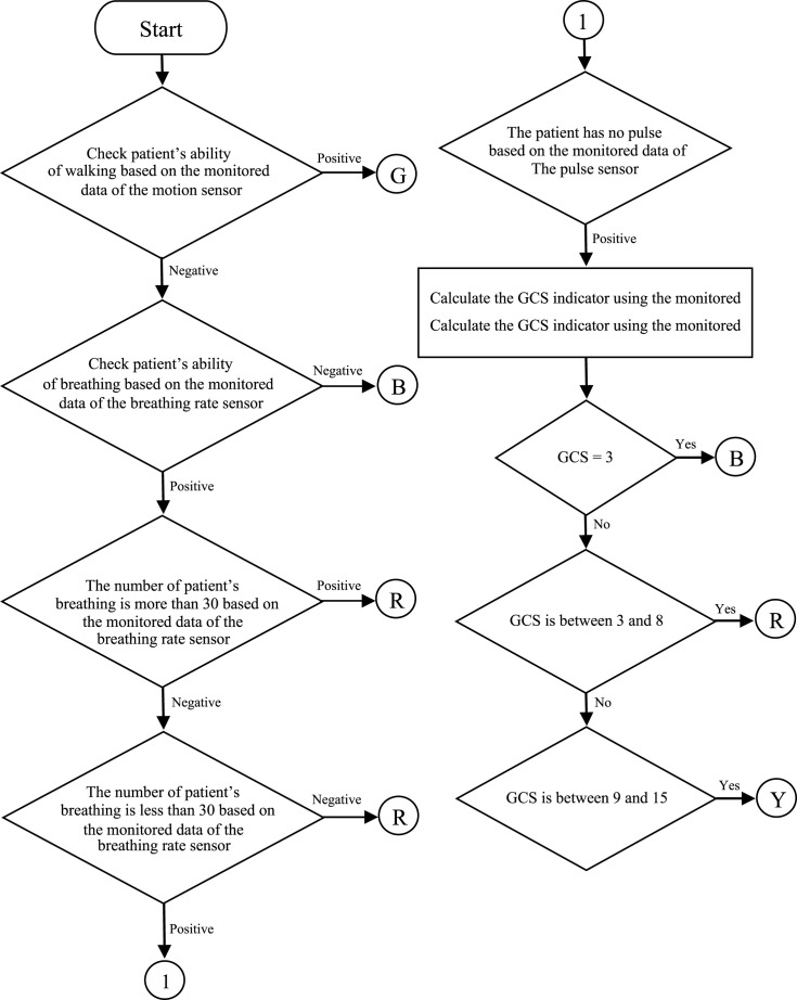
In this step, the data sensed by the sensors implanted in patient’s body are monitored and analyzed to compute Glasgow Coma Scale (GCS) and prioritize the patients. Depending on how critical the condition is, the patients are classified into four groups of dead (B), immediate (R), delayed (Y), and outpatient (G). Fig. 6 shows how the patients are prioritized based on the sensed data and GCS calculated by the given instructions of Table 4 [25], [26].
Fig. 6.
Flowchart of patient prioritization based on the sensed data and calculated GCS value.
In calculation of GCS, the sensed data and instructions of Table 4 are used to assign a number between 3 to 15 to the patient, which in turn is used for patient prioritization according to Fig. 6 [25], [26].
Table 4.
GCS calculation instruction using the data sensed by implanted sensors in patient’s body.
 |
5.7. The aggregation of the encryption-domain data of the th round, and transfer of 2-tuple including (encryption-domain aggregation data of the th round, the encryption-domain priority of th round) to the cloud
In this step, the received encryption-domain data of the th round is aggregated based on Eq. (10) in the sink node and is sent to the cloud as 2-tuple (encryption-domain aggregation data of the th round, the encryption-domain priority of th round) through the access point and the available infrastructure. In this approach, the security is guaranteed since all the data transmission and aggregations are occurred in encryption-domain.
| (10) |
Where, is the encryption-domain aggregation data of the th round, is the sensed data of the th round by sensor node No. , and shows, the related column of the sensor node No. in the th round measurement matrix.
5.8. The decryption and recovery of the received 2-tuple and determine the priority of patient
In this step, after receiving the 2-tuple sent by the sink node in the cloud, cloud decrypted and recovered data of received 2-tuple using the th round measurement matrix generated based on the random seed. Then, in the smart care center, the priority of the patient among other patients is determined according to the amount of .
An important point to address here is that in the decryption and recovery process in the cloud, we seek for the sparsest solution, which satisfies all the measurements. This solution is obtained by the problem in Eq. (11), where the zero-norm of the sensed data is minimized. However, the number of samples and the search space in the problem are very large and consequently, is NP-Hard. Therefore, instead of , the alternative problem in Eq. (12) is solved by relaxing the zero-norm [27].
| (11) |
| (12) |
In problem in Eq. (12), one-norm is used to minimize the samples taken. Norm is the closest convex relaxation of the zero-norm and if the condition stated in Eq. (13) is true in relation to the number of measurements, the answer to zero-norm will be the same as problem one.
| (13) |
Also, if consider the number of measurements and the number of samples in the data recovery process as the number of equations and the number of unknowns. Then, when the number of samples is more than the number of measurements (the number of unknowns is more than the number of equations), the system of equations does not have a unique solution but infinite solutions. So, we can select the sparsest solution from the available solutions for the optimum data recovery.
6. Analysis and evaluation of the results
In this section, simulation results are used to evaluate the described network topology of Section 4 in six test scenarios, with or without the proposed sensing model.
6.1. Assumptions and setting of parameters in the simulation to evaluate the performance of the proposed sensing model
To obtain accurate results in the present study, all tests and simulations were performed in a fair environment on a PC with a Core i3 2.5 GHz Intel® processor, a 4096 MB memory and a 64 bit Windows 7 operating system. To simulate the proposed sensing model and the comparison method, MATLAB R2019b was used. Assumptions were considered in the simulation according to Table 5.
Table 5.
Experiment’s assumptions.
| No. | Assumption |
|---|---|
| 1. | Each node knows its residual energy and location. |
| 2. | The sink node is different from other sensor nodes and has more resources (energy, memory, processing power, and transmission power) compared to them. |
| 3. | Each node has an Omni directional antenna. |
| 4. | The sensor and sink nodes are fixed at given locations. |
| 5. | The channel is collision-less. |
| 6. | Any signal is sparse in the linear-transform domain. |
| 7. | The measurement is linear. |
| 8. | The number of measurements is equal to or more than twice the sparsity level of the sensed data. |
| 9. | The measurement matrix has Restricted Isometry Property (RIP) and is suitable for the recovery of sparse or compressed data. |
| 10. | The number of data sensed by the sensor nodes is infinite. |
| 11. | The sparsity level of the sensed data is not fixed over time and changes for different data types sensed by the sensor nodes. |
| 12. | is uniformly distributed over . |
In addition, in the simulation, the body is implemented as a 2D medium with dimensions of 1.82 m 7.9 m, and the sensor nodes and the sink node are fixed at predefined locations given in Table 2 with an initial energy of 0.3 J and 0.525 J, respectively. In the analyses, data with 0.915 bits of entropy were considered and default measurements were set to 209. In addition, details of the setting of other parameters used in the simulation are presented in Table 6.
Table 6.
Details of parameters settings in the simulation.
| Parameter symbol | Parameter description | Value |
|---|---|---|
| R | Data transfer rate | 1 Mbps |
| C | The light speed | |
| Number of default measurements | 209 | |
| Time of distribution of activity intervals | 0.32 ms | |
| Number of sensor node | 4 | |
| Number of sink node | 1 | |
| Initial energy of sensor node | 0.3 J | |
| Initial energy of sink node | 0.525 J | |
| BPL | Body path loss | 3.2 dB |
| Default entropy level | 0.915 Bits | |
| Default compression ratio | 0.8164 | |
| N | Total number of unknowns in | 256 |
| Time of lightweight secure sensing | 0.0145 s | |
| Usage energy of lightweight secure sensing | 0.028 mj | |
| Reception energy dissipation | 36.1 nj/bit | |
| Transmission energy dissipation | 16.7 nj/bit | |
| Energy dissipation for addition | 3.3 nj | |
| Memory read energy dissipation | 0.26 nj | |
| Memory write energy dissipation | 4.3 nj | |
| Multiplication energy dissipation | 9.9 nj | |
| Shift energy dissipation | 3.3 nj | |
| Comparison energy dissipation | 3.3 nj | |
| X | Vector representing acquired signal | It is calculated dynamically |
| Number of nonzero coefficients (Default sparsity level) | 17 | |
| Measurement matrix in | It is calculated dynamically | |
| Y | Measurements in | It is calculated dynamically |
| Sensing power consumption | 15.01 mW | |
| Instruction execution duration | 0.135 | |
| Active listening period | 0.02 s | |
| Operation frequency | 7.4 MHZ | |
| Packet size of activity intervals | 48 bit | |
| Time of normal sensing | 0.346 ms | |
| Usage energy of normal sensing | 0.5 | |
| Background power consumption | 9.6 mW | |
| Sensing power consumption | 15.01 mW | |
| Time of DSCB sensing | 0.0180 s | |
| Usage energy of DSCB sensing | 1 mj |
6.2. Performance metrics
In the analysis and evaluation section, performance and security of the proposed scheme are evaluated using various performance metrics such as Average Energy consumption of Sensor Nodes (AESN), Average Packet Delivery Delay (APDD), Number of Dead Sensor Nodes (NDSN), the quality of the recovered signal, Impact of different entropy levels, mutual information, and Normalized Mutual Information (NMI).
6.2.1. Average energy consumption of sensor nodes
In this paper, the AESN given in Eq. (14), as an output parameter, is used to evaluate the performance of the proposed sensing model compared to the DSCB method [17].
| (14) |
In Eq. (14), , N, are the average energy consumption of sensor nodes, the total number of sensor nodes and the energy consumed by th sensor node to transfer sensed data to sink node, respectively, and is the amount of energy consumed by th sensor node to sense data using the proposed sensing model or sensing model used in DSCB [17]. This includes the energy consumed to sense raw data, energy consumption over compression and securing raw sensed data and energy consumption in the background.
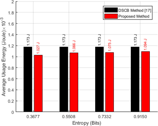
In Fig. 7, performance analysis of the proposed sensor model was shown in terms of average energy consumption in each sensor node on the network schematic presented in Section 4 and according to Eq. (14), when using the sensing model at different levels of entropy compared to the DSCB method [17].
Fig. 7.
Average energy consumption of the sensor nodes versus the different levels of entropy.
As indicated in Fig. 7, average energy consumption in sensor nodes in case of using the proposed sensor model improved compared to when the DSCB method was used [17]. For instance, the average energy consumption of sensor nodes improved by 6.72% when the entropy level of the sensed data was 0.9150 bits. This improvement is more dramatic in sensed data with lower levels of entropy, and the energy remaining in the sensor nodes approaches the threshold defined for node survival in more rounds. One of the reasons for the difference between the average energy consumption of sensor nodes in the proposed sensing model and the DSCB method [17], which increases with decreasing the level of entropy of the sensed data, is the sampling of sensed data with the number of dynamic measurements based on the amount of information content and the sparsity of sensed data which causes the data sensed in the proposed sensing model, with the same size as the data sensed in the DSCB method [17] to be sent with fewer bits and lower energy consumption than that of the DSCB method [17].
6.2.2. Analysis and evaluation of the average packet delivery delay
The average packet delivery delay is defined as the average time taken for packets sent by sensor nodes to be delivered to the sink node. Minimizing delay in any network, especially those with limited energy is of vital importance in order to extend the life of the network. In evaluating the efficiency of the proposed sensing model in comparison with the DSCB method [17], the average packet delivery delay was calculated using Eq. (15).
| (15) |
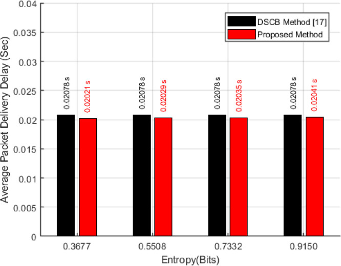
In Eq. (15), is the size of packet sent by th sensor node, is the data transfer rate, is the distance between th sensor node and sink node, and is the time allotted by the sink node to the sensor node at which the sensor node can be active and sense the data. In addition, the constant value C is for wireless connection which equals the light speed. In Fig. 8, the performance analysis of the proposed sensing model in comparison with the DSCB method [17] is shown in terms of average packet delivery delay at different levels of entropy when the data transfer rate is 1 Mbps.
Fig. 8.
Average packet delivery delay versus the different levels of entropy.
As indicated in Fig. 8, the average packet delivery delay, in the case of using the proposed sensing model and the level of entropy of the sensed data was 0.9150 bits, reduced by 1.82% compared to when using the DSCB method [17]. This is due to the sampling of data based on the information content and their level of sparsity, which causes the sensed data to be sampled with fewer measurements and transmitted with fewer bits. Therefore, with a constant data transfer rate and a constant value of C and the distance between the sensor nodes and the sink node, the average packet delivery delay decreases. here, packet delivery delay decreases directly related to the reduced level of entropy of sensed data, and This decrease is more dramatic in sensed data with lower levels of entropy.
6.2.3. Analysis and evaluation of the number of dead sensor nodes
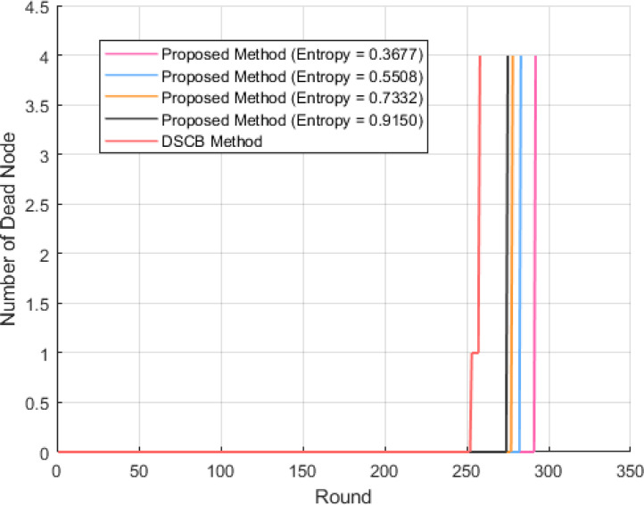
In routing protocols, the nodes with an energy level below a certain threshold are referred to as dead nodes. In this paper, the NDSN is considered as a performance metric to compare the proposed sensing model with its DSCB [17] counterpart method. In Fig. 9, the simulation results of the proposed sensing model are shown in terms of the number of dead nodes per rounds and at different levels of entropy compared to the DSCB method [17].
Fig. 9.
Number of dead sensor nodes versus the round for various levels of entropy.
As indicated in Fig. 9, the proposed sensing model has played an effective role in reducing and the uniformity of energy consumption of sensor nodes and increasing their lifetime. In the proposed sensing model, unlike the DSCB method [17], where the energy of the sensor nodes is consumed non-uniformly and one of the sensor nodes dies in round 250 while others sensor node die in round 258, all sensor nodes according to the level of entropy of the sensed data, die at higher round and simultaneously in the one-step, which indicates the stability and longer life of the network when using the proposed sensing model.
6.2.4. Analysis and evaluation of the impact of various levels of entropy
Entropy is one of the fundamental concepts in information theory that used as a criterion to measure uncertainty and information content. In a signal, entropy determines the degree of compressibility of the signal coefficients over a given range. The present study examines the quality of the reconstructed signals from signals with various entropy levels to evaluate the effect of various entropy levels on the performance of the proposed sensor model. In the performed simulation, the entropy level of the signal is calculated based on the Shannon standard using Eq. (16) and the signal quality according to Eq. (17) in Section 6.2.5.
| (16) |
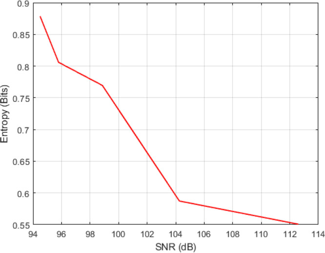
where is the number of samples, is the probability of occurrence of the th sample, and is the entropy of the sensed data vector. Fig. 10 indicates the performance of the proposed model in recovering signals with various levels of entropy.
Fig. 10.
The effect of various levels of entropy on the quality of the recovered signal.
As shown in Fig. 10, in the recovery done using Lightweight Secure Sensing Model, the signals recovered from low entropy signals have a higher signal-to-noise ratio than high entropy signals. This higher ratio is because only the sparse signal can be easily recovered by a Lightweight Secure Sensing Model as they have low entropy. Thus, as increasing entropy has an inverse effect on the quality of the recovered signal, it is tried to reduce significantly the negative effect of entropy level of the sensed signal on the quality of the recovered signal. For this purpose, the dynamic calculation of the number of measurements is done according to the sparsity of the sensed signal.
6.2.5. Analysis and evaluation of the quality of the recovered signal
To compare the quality of the recovered signal for the proposed sensing model and the DSCB method [17], two indicators of the signal to noise (SNR) and the distortion of the recovered signal are used. As SNR increases and distortion of the recovered signal decreases, the quality of the recovered signal improves to a more acceptable level. In the simulations, the SNR indicator and distortion index are calculated by Eqs. (17), (18), respectively [28], [29].
| (17) |
| (18) |
In Eqs. (17), (18), , , and are the original signal, the recovered signal, and the mean of the original signal, respectively.
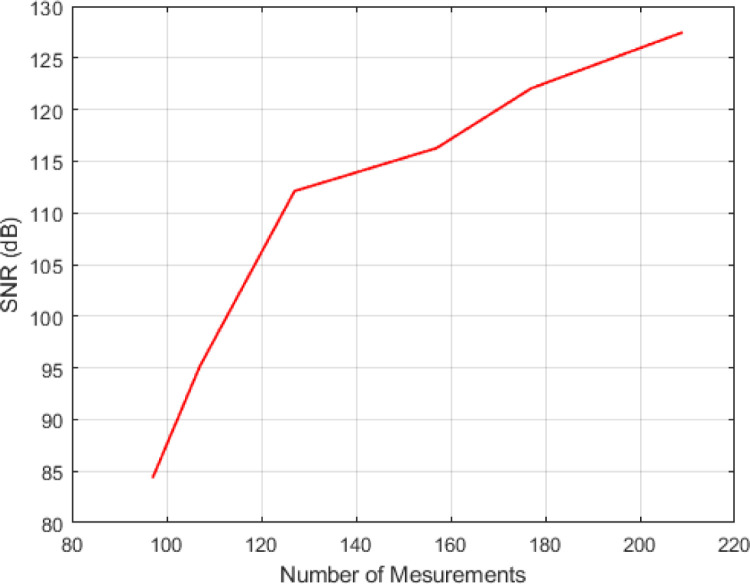
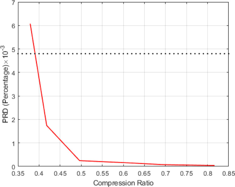
Fig. 11(a), Fig. 11(b) compare the quality of the recovered signal for the proposed sensing model and DSCB method [17], where the distortion index and SNR are plotted for various values of the compression rate and the number of measurements.
Fig. 11(a).
SNR of the recovered signal for various values of the number of measurements.
Fig. 11(b).
Distortion index of the recovered signal for various values of the compression rate.
As can be seen in Fig. 11(a), Fig. 11(b), the quality of the recovered signal improves when the original signal is sampled with a higher compression coefficient and more number of measurements. For instance, the best recovery quality is obtained for the compression rate and the Percentage Root-mean square Difference (PRD) of 0.81 and , respectively.
When PRD is less than , the quality of the recovered signal is acceptable for medical diagnosis. The PRD can be more than for computer diagnosis. For the compression rate below 0.2, the identification quality is not acceptable, since the peaks cannot be properly detected for the severely distorted recovered data.
6.2.6. Analysis and evaluation of the security in the proposed sensing model
To analyze the security of the proposed sensing model, the communication of the sensor nodes and the sink node is exposed to the brute force attack. In the proposed sensing model, the received signal can be only recovered if the measurement matrix is accessible. We assume that the attacker uses trial and error to obtain the measurement matrix. Since the measurement matrix is randomly generated in each round, even if the intruder can detect the measurement matrix in a round, the obtained matrix cannot be used for the next round.
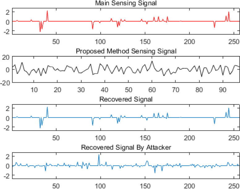
Let denote the measurement matrix used by the intruder to recover the sensed signal. For the proper and complete recovery, , otherwise, the recovered signal has a high level of noise and is not recoverable, as shown in Fig. 12.
Fig. 12.
Main sensing signal, signal of the proposed method, recovered signal by the permitted person, and recovered signal by the attacker.
If denotes the number of the identical rows in the main measurement matrix and the measurement matrix obtained by the attacker , and if is the ratio of the identified rows by the attacker to the total number of rows in the main measurement matrix, is
| (19) |
To determine the security level of the proposed sensing model against the brute force attack, the mutual information test can be used. In this test, we assume that the dimension of the signal sensed by the sensor nodes, the sparsity level of the signal, and so on are known for the intruder while the attacker has no full knowledge of the measurement matrix .
6.2.6.1. Mutual information.
The mutual information of the main and recovered signals, and , is computed by [30]
| (20) |
where is the mutual information between the main and recovered signals, and . In fact, specifies the amount of information that the main signal gives about the recovered signal , and inversely, the amount of information that the recovered signal gives about the main signal . As decreases, the common information between the main and recovered signals, and , reduces.
In the third line of Eq. (20), since the main signal has no data, the recovered signal has no data, too, and therefore, their mutual information is zero. Therefore, the third line can be simplified to the fourth line of Eq. (20). In the fourth line of Eq. (20), since the number of measurements is assumed to be equal to or greater than twice the sparsity level of the main signal, each recovered signal can have a unique prediction and a uniform distribution according to the main signal. Moreover, the recovered signal has a uniform distribution over encryption operations applied over . So, we have
On the other hand, in the fifth line of Eq. (20), since is uniformly distrusted over , we get
Obviously, when the number of signals approaches infinite, the mutual information of the main and recovered signals is zero and the security is guaranteed.
Defining as the mutual information between the signal sensed by the sensor node and the signal recovered by the sink node, and as the mutual information between the main signal and the signal recovered by the intruder, the NMI is obtained by
| (21) |
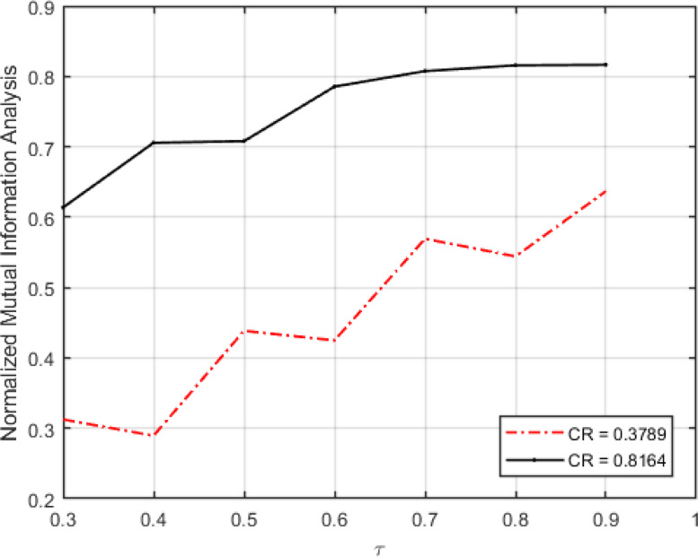
Fig. 13 shows the NMI versus various values of for the signals obtained from sensor nodes.
Fig. 13.
Normalized mutual information versus the number of rows identified by the intruder to the total number of rows of the measurement matrix.
As can be seen in Fig. 13, the mutual information between the signal sensed by the sensor node and the signal recovered by the sink node is 2 to 3 times more than the mutual information between the main signal and the signal recovered by the intruder when the compression rate and consequently, the quality of the results are high. The results clearly show that the information decrypted by the attacker is marginal and useless and therefore, the attacker is not able to exploit the encrypted signal.
7. Conclusions and future works
In this paper, we tried to focus on one of the challenging problems of the BANs, named routing, its comparative analysis, and investigation of its features and advantages to provide a better perception for the introduced routing protocols in BANs as well as propose a sensing model, which improves the issues of security and energy consumption as much as possible and suits BANs with clinical healthcare applications. In the proposed sensing model, the data sensed by the sensor nodes is securely sampled by a lower number of bits and then, this sparse sensed data with medium and high dimensions is recovered from a low number of measurements. We used simulation results to compare the performance of this sensing model with that of the DSCB method [17] in terms of the capabilities of sampling the sensed data and its recovery. We also analyzed and evaluated the proposed sensing model in terms of the security and demonstrated that we can obtain Shannon’s perfect security by guaranteeing uniform distribution condition and limiting the number of measurements. Moreover, we showed how the proposed sensing model improves the security, quality of the recovered signal, and performance of the BAN in terms of the network lifetime, APDD, and AESN.
In this research, we considered data with different levels of entropy in our tests. moreover, we considered the recovery error in data sampling, and we sampled data based on their sparsity level and amount of information content with a dynamic amount of measurement. As our experiments show, as the number of measurements increases and approaches the total number of signal samples, the recovered signal is much similar to the original signal. However, in our analysis, we found that the signal quality does not play the key role in medical diagnosis and a medium-quality recovered signal enables the doctors to make a correct diagnosis. On the other hand, increasing the number of measurements makes the illegal recovery of the main signal complicated for the intruder. Therefore, we tried to adjust the number of measurements to preserve the signal quality, guarantee security, and improve other quality of service parameters.
As future work, we plan to propose a multi-bit sensing model, where a unique biological feature is used to generate the measurement matrix Then, we combine the proposed sensing model with an offered applied triage for COVID-19, and use it for outbreak prevention and detection.
Declaration of Competing Interest
The authors declare that they have no known competing financial interests or personal relationships that could have appeared to influence the work reported in this paper.
References
- 1.Yuce M.R. Implementation of wireless body area networks for healthcare systems. Sensors Actuators A. 2010;162:116–129. [Google Scholar]
- 2.Rajasekaran S., Kumaran P., Premnath G., Karthik M. Human health monitoring using wireless sensors network (WSN) Int. J. Appl. Innov. Eng. Manag. 2013 [Google Scholar]
- 3.I. Chiuchisan, I. Chiuchisan, M. Dimian, Internet of Things for e-Health: An approach to medical applications, in: 2015 International Workshop on Computational Intelligence for Multimedia Understanding, IWCIM, 2015, pp. 1–5.
- 4.Uniyal D., Raychoudhury V. 2014. Pervasive healthcare-a comprehensive survey of tools and techniques. arXiv preprint arXiv:1411.1821. [Google Scholar]
- 5.Altop D.K., Levi A., Tuzcu V. Deriving cryptographic keys from physiological signals. Pervasive Mobile Comput. 2017;39:65–79. [Google Scholar]
- 6.Yessad N., Bouchelaghem S., Ouada F.-S., Omar M. Secure and reliable patient body motion based authentication approach for medical body area networks. Pervasive Mobile Comput. 2017;42:351–370. [Google Scholar]
- 7.Bayilmis C., Younis M. Energy-aware gateway selection for increasing the lifetime of wireless body area sensor networks. J. Med. Syst. 2012;36:1593–1601. doi: 10.1007/s10916-010-9620-y. [DOI] [PubMed] [Google Scholar]
- 8.Elias J. Optimal design of energy-efficient and cost-effective wireless body area networks. Ad Hoc Netw. 2014;13:560–574. [Google Scholar]
- 9.Latré B., Braem B., Moerman I., Blondia C., Demeester P. A survey on wireless body area networks. Wirel. Netw. 2011;17:1–18. [Google Scholar]
- 10.Javaid N., Abbas Z., Fareed M., Khan Z.A., Alrajeh N. M-ATTEMPT: A new energy-efficient routing protocol for wireless body area sensor networks. Procedia Comput. Sci. 2013;19:224–231. [Google Scholar]
- 11.S. Ahmed, N. Javaid, M. Akbar, A. Iqbal, Z.A. Khan, U. Qasim, LAEEBA: Link aware and energy efficient scheme for body area networks, in: 2014 IEEE 28th International Conference on Advanced Information Networking and Applications, 2014, pp. 435–440.
- 12.Srinivas M. Cluster based energy efficient routing protocol using ANT colony optimization and Breadth first search. Procedia Comput. Sci. 2016;89:124–133. [Google Scholar]
- 13.Khan R.A., Mohammadani K.H., Soomro A.A., Hussain J., Khan S., Arain T.H. An energy efficient routing protocol for wireless body area sensor networks. Wirel. Pers. Commun. 2018;99:1443–1454. [Google Scholar]
- 14.Abidi B., Jilbab A., Mohamed E.H. An energy efficiency routing protocol for wireless body area networks. J. Med. Eng. Technol. 2018;42:290–297. doi: 10.1080/03091902.2018.1483440. [DOI] [PubMed] [Google Scholar]
- 15.Saranya V., Shankar S., Kanagachidambaresan G. Energy efficient clustering scheme (EECS) for wireless sensor network with mobile sink. Wirel. Pers. Commun. 2018;100:1553–1567. [Google Scholar]
- 16.Yan J., Peng Y., Shen D., Yan X., Deng Q. An artificial bee colony-based green routing mechanism in WBANs for sensor-based e-healthcare systems. Sensors. 2018;18:3268. doi: 10.3390/s18103268. [DOI] [PMC free article] [PubMed] [Google Scholar]
- 17.Ullah Z., Ahmed I., Razzaq K., Naseer M.K., Ahmed N. DSCB: Dual sink approach using clustering in body area network. Peer Peer Netw. Appl. 2019;12:357–370. [Google Scholar]
- 18.Ullah F., Ullah Z., Ahmad S., Islam I.U., Rehman S.U., Iqbal J. Traffic priority based delay-aware and energy efficient path allocation routing protocol for wireless body area network. J. Ambient Intell. Humaniz. Comput. 2019;10:3775–3794. [Google Scholar]
- 19.Kaleem M., Mahapatra R. Energy consumption using network stability and multi-hop protocol for link efficiency in wireless body area networks. J. Comput. Eng. 2014;163:113–120. [Google Scholar]
- 20.Khan M.M., Abbasi Q.H., Alomainy A., Parini C. Experimental investigation of subject-specific on-body radio propagation channels for body-centric wireless communications. Electronics. 2014;3:26–42. [Google Scholar]
- 21.Hu Y., Ping L. Multiple Access Techniques for 5G Wireless Networks and beyond. Springer; 2019. Interleave division multiple access (IDMA) pp. 417–449. [Google Scholar]
- 22.M. Lopes, Estimating unknown sparsity in compressed sensing, in: International Conference on Machine Learning, 2013, pp. 217–225.
- 23.F. Salahdine, N. Kaabouch, H. El Ghazi, One-bit compressive sensing vs. multi-bit compressive sensing for cognitive radio networks, in: 2018 IEEE International Conference on Industrial Technology, ICIT, 2018, pp. 1610–1615.
- 24.Baraniuk R.G. Compressive sensing [lecture notes] IEEE Signal Process. Mag. 2007;24:118–121. [Google Scholar]
- 25.Khan K. Tabletop exercise on mass casualty incident triage, does it work? Health Sci. J. 2018;12 [Google Scholar]
- 26.Teasdale G. Forty years on: updating the Glasgow Coma Scale. Nurs. Times. 2014;110:12–16. [Google Scholar]
- 27.M. Hyder, K. Mahata, An approximate l0 norm minimization algorithm for compressed sensing, in: 2009 IEEE International Conference on Acoustics, Speech and Signal Processing, 2009, pp. 3365–3368.
- 28.Lavrenko A., Romer F., Galdo G.D., Thoma R. On the SNR variability in noisy compressed sensing. IEEE Signal Process. Lett. 2017;24:1148–1152. /08 2017. [Google Scholar]
- 29.D. Mitra, H. Zanddizari, S. Rajan, Improvement of signal quality during recovery of compressively sensed ECG signals, in: 2018 IEEE International Symposium on Medical Measurements and Applications, MeMeA, 2018, pp. 1–5.
- 30.Cover T., Thomas J. John Wiley and Sons, Inc; NY: 1991. Elements of Information Theory; pp. 33–36. [Google Scholar]


