

Abstract
Objective
The emergence of distraction‐based growing rods has provided the means to reduce the progression of spinal deformity in early onset scoliosis (EOS). The current protocols for evaluating spinal implants (ie, ASTM‐F1717 and ISO‐12189) were developed for fusion/dynamic devices. These protocols do not feature long unsupported rod lengths subjected to distraction. Due to the unsuitability of the existing guidelines for the evaluation of growing rods, a new distraction‐based finite element protocol is presented herein for the first time.
Method
A vertebrectomy (VO) model from current protocols was modified to accommodate multi‐spinal segments (ie, MS model) in which springs with appropriate stiffness were simulated in between the plastic blocks. To assess the efficacy of the protocol, two different computational studies were conducted: (a) compression‐bending (MS‐CB) with no distraction, and (b) distraction followed by compression‐bending (MS‐D + CB). In each study, the model with no axial connector (rods‐only) was modified to include a) 80‐mm long tandem (LT) connectors, and b) side‐by‐side (SBS) connectors. Stiffness and yield loads were calculated as per ASTM‐F1717 guidelines and compared with the corresponding VO models with no distraction. In the MS‐D + CB models, distraction was applied at the top block, stretching the spring‐block construct in a simulation of scoliosis surgery prior to locking the construct at the connector‐rods' interface.
Results
MS‐CB models predicted higher stiffness and yield loads, compared to the VO models. The locking mechanism produced pre‐existing stresses on the rod‐connector interface, which caused a shift in the location of high‐stress regions to the distraction site. Distraction led to a decrease in the construct's stiffness and yield load.
Discussion
The proposed protocol enables the simulation of clinical parameters that are not feasible in the F1717 models and predicted stress patterns in the hardware consistent with observed clinical failures.
Keywords: ASTM‐F1717, Distraction, Finite Element Analysis, Scoliosis, Traditional Growing Rods (TGRs)

1. INTRODUCTION
Early onset scoliosis (EOS) is a lateral curvature of the spine, developing in patients less than 10 years old. 1 The emergence of distraction‐based growing rods has provided the ability to correct spinal deformity in these patients. These nonfusion devices restore spinal alignment while permitting spinal growth through distraction surgeries. Following the initial surgery, the single or dual growing rods undergo multiple distractions at intervals. This continues through skeletal maturity when the patient is old enough for spinal fusion. More recently, magnetic technology with adjustable growing rods and an external remote controller (ERC) have been used to help avoid distraction surgeries during the treatment for EOS and thus reduce associated complication‐risks from repetitive surgeries.
In traditional growth rod surgeries, a variety of connectors (ie, side‐by‐side (SBS), short tandem (ST), long tandem (LT)) may be used, based on the surgeon's preference and patient's anatomy. 2 These connectors allow for rod lengthening as the patient grows. Surgeons may choose different combinations of connectors while considering the curve type and magnitude. 3 The use of connectors in growing rods is associated with complications (such as rod fracture, screw loosening 1 ). Therefore, studies have delineated the effects of different parameters, including varying configurations of axial connectors as well as distraction frequency and lengthening magnitude, on the growing rod fracture rate 1 , 3 , 4 , 5 , 6 , 7 , 8 , 9 , 10 .
To enhance the clinical success of the new growing rod designs, it is essential to undertake a bench‐top evaluation of the devices. The test protocols should be clinically relevant and should predict failure loads and locations seen in the patients. The protocols also need to be simple enough to provide a basic assessment of the implants' strength. The current standards (ie, ASTM‐F1717, 11 and ISO‐12189 12 ) have been modified to be a better representative of the real‐life performance of posterior spinal implants 2 , 13 , 14 , 15 , 16 , 17 , 18 , 19 , 20 , 21 , 22 , 23 , 24 , 25 . However, these modifications still are not suitable for the evaluation of growing rods.
ASTM‐F1717 (also known as the missing vertebra/ vertebrectomy (VO) model protocol 11 ) simulates the worst‐case scenario to evaluate the mechanical performance of fusion devices. 11 La Barbera et al. modified different biomechanical parameters stated in the standard (such as moment arm, and unsupported screw length) based on the physiological range of data collected from literature 16 , 21 . The numerical and experimental results from their revised protocol showed an increase in the stresses on spinal fixation devices (up to 50% on the screw, 11% on the rod) and decreased the cycles to failure considerably 16 , 21 , compared to standard ASTM F‐1717 protocol.
The ISO‐12189 was developed to evaluate posterior dynamic stabilization devices 12 and further modified over the years 17 , 18 , 22 . Due to the presence of the anterior support and its load sharing with spinal implants, authors claimed that ISO‐12189 simulated a more realistic scenario, compared with ASTM‐F1717 19 , 20 , 23 , 24 .
In the literature, only a few authors have modified the ASTM‐F1717 guideline to assess the mechanical properties of growing rods (growing rods with axial connectors across a two vertebrae segment) 2 , 13 , 14 , 15 , 25 . Given the unsuitability of the VO model for evaluation and the relatively high rate of mechanical failures of growing rods (15‐25%), 7 a new protocol is warranted. Thus, to model a more physiological loading environment, a new finite element (FE)‐based protocol is presented, which accommodates long distraction‐based growing rod constructs spanning over multiple segments with anterior supports across each segment.
In developing this protocol, it was hypothesized that besides predicting failure locations that are clinically relevant, the role of various parameters such as axial connector's configurations (ie, shape, length, and location of connectors), and the effects of distraction could be investigated. Thus, the VO model was modified to accommodate more than one nonfixed spinal segment with the simulation of springs in between plastic blocks and axial connectors. Second, the proposed protocol allows simulation of rod distraction, locking in situ and then relaxation of springs prior to compression‐bending (CB) analysis.
2. METHODS
Models were created in SolidWorks (Dassault Systèmes SolidWorks Corporation, Waltham, USA), based upon ASTM‐F1717 protocol. 11 To establish a comparison of biomechanical data between the proposed and currently available models, the vertebrectomy (VO) model was reproduced as per Hill et al. (Figure 1A). 2 In each model, as per ASTM‐F1717, the active length was defined as the distance between the center of the attachment in the superior and inferior most anchors, 11 which was 204 mm (based upon the average length for juvenile thoracolumbar constructs 4 ). To investigate the biomechanics of various clinically relevant parameters, we simulated three different VO models: (a) no connector (rods‐only [RO]), (b) 80‐mm long tandem (LT), and (c) side‐by‐side (SBS) connector (Figure 1). No distraction was simulated, being missing vertebra models. The model with no connector (RO) was developed as a baseline model. All connectors were positioned centrally on the rods, and SBS connectors were placed with a horizontal offset of 6.25 mm. These VO models simulated dual 5.5 mm rods and 4.5 mm pedicle screws.
FIGURE 1.

Three‐dimensional view of the models developed for A, vertebrectomy (VO), and B, multi‐segment (MS) models. For each model from left to right: no axial/rods‐only (RO), 80‐mm long tandem (LT), and side‐by‐side (SBS) connector are shown. The active length of the rods was 204 mm. SBS connector was positioned with an offset of 6.25 mm. Distraction was applied at the superior most plastic blocks of the MS models prior to locking the rods through the connectors
The proposed multi‐segment (MS) models (Figure 1B), consisted of five plastic blocks connected by four sets of springs. These springs simulated the cumulative stiffness of the discs, facets, and ligaments. All of the plastic blocks were modeled as ultra‐high‐molecular‐weight polyethylene (UHMWPE). The top and bottom most blocks were sized to accommodate pedicle screws, while the size of the center blocks was minimized to prevent contact with the scoliosis hardware (Figure 2). MS models also simulated dual 5.5 mm rods and 4.5 mm pedicle screws. Axial connectors were similar to the VO models (RO, LT, and SBS).
FIGURE 2.

Three‐dimensional view of the middle blocks used in the multi‐segment models. The middle blocks were rectangular in shape with rounded edges to avoid any interaction between the blocks and the growing rods. As per ISO‐12189, circular indents were of 3.5 mm in depth to accommodate spring simulations between adjacent blocks. Dimensions are in mm
3. SELECTION OF APPROPRIATE SPRINGS
Since the springs represented the cumulative effect of intervertebral joint mobility (ie, discs, facet, and ligaments) under the applied distraction force, clinical data was used to find appropriate stiffness 5 , 6 . The clinical data pertained to the applied distraction force vs T1‐S1 height gain at consecutive intervals.
In a pediatric patient, the spinal segment is distracted the desired amount by the surgeon, and then the growing rods which are loose to start with are locked in place. The patient undergoes multiple distractions to lengthen and correct the spine. Since the distraction force depends on a multitude of factors (eg, patient's age, pre‐ and post‐ Cobb angles, motion segment stiffness), and varies at each interval, these values were averaged for the first three episodes of distraction surgeries (distraction force = 193.7 N, total displacement = 10.3 mm). We assumed a typical spinal implant covers 10 FSUs from T4 to L2 for a pediatric spine. Therefore, the average displacement was reduced proportionally with respect to 10 FSUs. Thus, the appropriate displacement for the selected active length was 6.0 mm . Springs were assembled in a MS model, which was distracted from the head of the superior most screws (with the distractive load equal to 193.7 N) without the presence of growing rods (ie, springs were subjected to tension/distraction). This process was repeated for different spring constants (selected from the catalog 26 ) until the overall displacement was as close to 6 mm as possible for the applied distraction force. Finally, at each “FSU”, two standard red die springs (ISO 10243 standard 27 for metric die springs) with stiffness of 129 N/mm were selected for simulation (Table 1 26 ). The selected springs produced 6.22 mm displacement at 193.7 N; within 5% of 6.0 mm.
TABLE 1.
Mechanical properties of the springs used in the multi‐segment (MS) models 26
| Spring type | Die |
|---|---|
| Color | Red |
| Hole diameter | 20 mm |
| Shaft diameter | 10 mm |
| Length | 38 mm |
| Wire | |
| Thickness | 3.18 mm |
| Width | 4.19 mm |
| Compressed length at maximum load | 27 mm |
| Deflection at maximum load | 25% |
| Maximum load | 1223.26 N |
| Rate | 129 N/mm |
| Material | Chrome‐silicon steel |
Abbreviations: MS, multi‐segment.
4. FE MODEL SPECIFICATIONS
After assembled in SolidWorks, models were imported into ABAQUS/Standard v6‐14 (Dassault Systèmes, 22 Simulia, Waltham, USA) to generate the quasi‐static FE models. Springs were meshed in FE using a 10‐node quadratic tetrahedron (C3D10) element. An eight‐node linear tetrahedron (C3D8) was used for the rods, and a four‐node linear tetrahedron (C3D4) was used for all other components. Seed sizes were determined from a preliminary mesh convergence study in which an initial seed size was assigned to the rods in the MS model with rods and no axial connectors. The load‐displacement data in CB was obtained. Subsequently, the mesh was refined until the difference between the subsequent construct's stiffness reached below 3%. 2 Finer mesh size was used for the spinal implants (ie, rods, screws, and axial connectors), compared to the plastic blocks. The seed sizes on the axial connectors were selected in a way that there was a uniform element size transition throughout the rod‐connector connection. Material properties for different components were adapted from literature 2 (Table 2).
TABLE 2.
Material properties and element types for all components in multi‐segment and vertebrectomy (MS/VO) models. Material properties were adapted from literature 2
| Components | Material | Elastic properties | Plastic properties | Element type | ||
|---|---|---|---|---|---|---|
| Modulus of elasticity (MPa) | Poisson's ratio | Yield stress | Plastic strain | |||
| Blocks | UHMWPE | 690 | 0.46 | – | – | Four node linear tetrahedron (C3D4) |
| Screws/axial connectors | Titanium alloy (Ti6Al4V) | 105 000 | 0.36 | 600 750 880 935 970 1153.6 | 0 0.00148571 0.00338571 0.00519048 0.00828571 0.107614 | Four node linear tetrahedron (C3D4) |
| Rods | Titanium alloy (Ti6Al4V) | 105 000 | 0.36 | Eight node linear tetrahedron (C3D8) | ||
| Springs | Chrome‐silicon steel | 207 000 | 0.29 | – | – | Ten node quadratic tetrahedron (C3D10) |
Abbreviations: MS, multi‐segment; UHMWPE; ultra‐high‐molecular‐weight polyethylene.
In order to secure the springs between the plastic blocks and to allow tension to develop upon distraction, a reference point was defined at the center of the spring's end plane. This reference point was then coupled to the flat end surface of the springs as well as the corresponding nodes on the blocks. Thus, no relative motion between these two surfaces was permitted. Screws (with no threads being simulated) were bonded to the plastic blocks and rods using the tie option. Furthermore, a tie constraint was utilized at the inferior interface of the rods to the connectors. Ideally, the screws and axial connectors are connected to the rods with set screws, which are design specific and hence not simulated here.
A displacement‐controlled FE analysis was used for the MS and VO models with different axial connectors. Two studies were conducted separately on MS models to investigate the effect of distraction: (a) MS‐CB alone, and (b) distraction of the springs (as explained above) and locking of growing rods through axial connectors. Due to tension in springs locked in place through growing rods, construct exhibited relaxation. Consequently, MS‐D + CB was simulated. The VO models were subjected only to compression‐bending (no distraction) to compare the results.
In each model, to apply the boundary conditions, two reference points were defined on the superior‐ and inferior most blocks and were coupled to the respective surfaces. These reference points were located at a midpoint between two spring attachments. For each study, appropriate boundary conditions, as described in the next section, were applied to the reference points.
5. COMPRESSION‐BENDING ONLY (MS‐CB)
The MS and VO models were subjected to a quasi‐static compression‐bending‐ analysis. At the cranial rod‐connector interface, a tie constraint was defined. X, Y, and Z‐axis represented the anterior‐posterior, superior‐inferior, and medial‐lateral directions, respectively. Up to 40 mm compressive longitudinal displacement (along Y direction) was applied to the superior most block. The top block was constrained along the X and Z directions and rotation about the Y‐axis. The bottom block was constrained in all three directions and rotation about Y.
6. DISTRACTION FOLLOWED BY COMPRESSION‐BENDING (MS‐D + CB)
To investigate the effects of distraction on the growing rod mechanics, a three‐step analysis was performed on the MS models, as explained above. Coupling and constraints were similar to MS‐CB models except for the distraction/locking at the connector site. In order to mimic the distraction process in the actual surgery, appropriate surface‐to‐surface interactions were applied at the rod‐connector interface (rod‐screw interface for RO model) at each step (Table 3). Boundary conditions were defined on the top and bottom most blocks to simulate the following motions.
TABLE 3.
Details of the FE simulation for MS‐D + CB models
| Step 1: Distraction | Step 2: Spring relaxation | Step 3: Compression‐bending | |
|---|---|---|---|
| Surface to surface interaction at rod‐connector interface | Frictionless tangential behavior Linear normal behavior | Rough tangential behavior Hard normal behavior | Rough tangential behavior Hard normal behavior |
| Top block's BC | 6.22 mm longitudinal displacement along Y direction Constrained along X and Z directions and rotation about Y‐axis | No external load/displacement Constrained along X and Z directions and rotation about Y‐axis | Up to 40 mm longitudinal displacement along negative Y direction Constrained along X and Z directions and rotation about Y‐axis |
| Bottom block's BC | Constrained along X, Y, and Z directions and rotation about Y | Constrained along X, Y, and Z directions and rotation about Y | Constrained along X, Y, and Z directions and rotation about Y |
Abbreviations: CB, Compression‐bending; FE, finite element; MS, multi‐segment.
In the first step (Figure 3‐AB), the models were distracted. A frictionless surface‐to‐surface interaction was defined at the distraction site. Distraction site refers to the cranial rod‐connector interface for LT and SBS models (in the RO model, it was defined as the interface between the top head screw and rod). The top block was distracted by 6.22 mm longitudinally (along Y direction) while it was constrained along X and Z directions and rotation about Y‐axis. This displacement was based upon the spring displacement under 193.7 N distraction force (see “Selection of Appropriate Springs” section). In this step, the bottom block was constrained along X, Y, and Z directions and rotation about Y. At the end of this step, springs were under tension (from the distraction), and rods were not loaded (due to the sliding at the distraction site).
FIGURE 3.
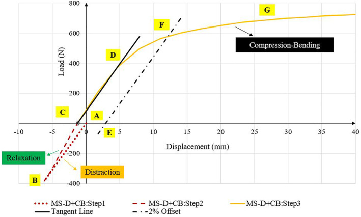
Typical load–displacement curve for MS‐D + CB models. Positive and negative values indicate compression and tension, respectively. First, models were distracted from the distraction site (dotted line: AB). In the second step, rods were locked into position with no external load on the models (dashed line: BC). Springs and rod were allowed to reach equilibrium. In the last step, models were subjected to compression‐bending (solid line: CG) until they reach their yield point. Point C indicated the initial displacement before compression‐bending, which varied between all models. Stiffness values were calculated as the slope of the initial linear section of the load‐displacement graph (line CD) as per ASTM‐F1717. The yield load corresponding to the permanent deformation of 2% of active length was calculated (see line EF)
In the second step (relaxation, Figure 3‐BC), rods were locked into position, and springs were allowed to release their tension to reach an equilibrium with locked growing rods. In this step, no relative sliding motion was allowed at the locking sites. Locking site refers to the interface between the lengthened rod‐segments and connector (lengthened rod and top head screw for RO model). To simulate the locking mechanism, a surface‐to‐surface interaction with rough tangential behavior and a hard‐normal behavior was defined. In this step, the top block was not subjected to any external force or displacement. The only force was the internal compressive load applied from the stretched springs. At the end of this step, the construct was in a state analogous to a corrected scoliotic spine with the patient laying supine after a distraction surgery. With no external loading on the construct, the rods were loaded as they maintained the distraction of the blocks with anterior spring support.
Finally, the model was subjected to compression‐bending (Figure 4‐CG). Surface‐to‐surface interactions at the locking site were similar to the second step (ie, relaxation), and boundary conditions were similar to MS‐CB models (see Table 3).
FIGURE 4.

Compressive load‐displacement curves for A, the vertebrectomy (VO) models subjected to compression‐bending, B, the multi‐segment models subjected to compression‐bending (MS‐CB), and C, the multi‐segment models subjected to distraction followed by compression‐bending (MS‐D + CB). In each figure, side‐by‐side (SBS, dashed line) and long tandem (LT, solid line) connectors increased the stiffness and yield load compared to rods‐only (RO, dotted line). The multi‐segment model (Figure 4B) increased the stiffness and yield load compared to the VO model (Figure 4A). Distraction (MS‐D + CB, Figure 4C) caused a decrease in stiffness and yield load in the multi‐segment model compared with compression‐bending only (MS‐CB, Figure 4B). All the model's outputs are nonlinear
7. DATA ANALYSIS
Although the springs' material properties were assumed linear elastic, the properties of the scoliosis hardware (ie, rods, screw, and connectors) were elastoplastic. This combination of material properties in compression‐bending led to the nonlinear load‐displacement graphs (Figures 3, 4). The stresses in the rods and axial connectors were obtained. Compressive reaction force at the superior most block along Y direction was computed to draw load‐displacement graphs. Stiffness values from all models were measured as the slope of the first linear section of the load‐displacement graph (slope of line CD, Figure 3). Per ASTM‐F1717 standard, 11 the yield load corresponding to the permanent deformation of 2% of active length was calculated for MS‐CB models. To calculate the yield load for the distracted rods, the active length was updated (210.22 mm, the intersection of line EF with the load‐displacement graph, Figure 3). To investigate the effect of the anterior support, the MS‐CB models were compared with the VO models, and the percentage difference in stiffness/yield load was normalized to the VO models (eg, [“MS‐CB”‐VO]/VO*100%).
Furthermore, to investigate the effect of distraction, the percentage differences in stiffness, yield load, and von Mises stresses were normalized to MS‐CB models (“MS‐D + CB”‐“MS‐CB”/”MS‐CB” *100%).
8. RESULTS
8.1. Compression‐bending analysis: MS‐CB vs VO models
Simulating the springs in between the blocks in the MS models (MS‐CB) increased the rigidity of the construct, compared with VO model predictions (Figure 4A,B and Table 4). Likewise, the yield load in the MS‐CB models increased compared to VO models (Table 4).
TABLE 4.
Comparison between the vertebrectomy (VO) and multi‐segment (MS‐CB) models subjected to compression‐bending
| Stiffness (N/mm) | Yield load(N) | |||||
|---|---|---|---|---|---|---|
| MS‐CB | VO | Percentage difference in stiffness | MS‐CB | VO | Percentage difference in yield load | |
| RO | 76.3 | 22.6 | 238% | 642.4 | 449.5 | 43% |
| SBS | 77.8 | 24.1 | 223% | 655.4 | 467.9 | 40% |
| LT | 82.5 | 31.6 | 161% | 752.3 | 606.6 | 24% |
Note: The percentage difference in stiffness/yield load was normalized to the VO models. MS‐CB models showed higher stiffness and yield load compared to respective VO models. None of the models were subjected to distraction.
Abbreviations: CB, Compression‐bending; LT, long tandem; MS, multi‐segment; RO, rods‐only; SBS, side‐by‐side.
With respect to the critical stress locations, RO and LT models under CB exhibited high von Mises stresses adjacent to distal anchor (635.7 and 690.4 MPa, respectively, Table 6). However, using the SBS connector shifted the high‐stress region to adjacent the proximal anchor (681.2 MPa, Table 6). Results showed that using the SBS, and LT connectors increased the maximum von Mises stresses.
TABLE 6.
Maximum von Mises stress values at three high‐stress regions on the growing rods (ie, adjacent to the proximal anchor, axial connector, and distal anchor)
| Loading condition | Model | Maximum von Mises stress values on rods (MPa) | |||
|---|---|---|---|---|---|
| Adjacent to the proximal anchor | Adjacent to the axial connector (mid construct) | Adjacent to the distal anchor | |||
| Compression‐bending Only | MS‐CB | RO | 570.1 | 313.3 | 635.7 |
| SBS | 681.2 | 311.6 | 672.7 | ||
| LT | 452.2 | 457.9 | 690.4 | ||
| Distraction followed by compression‐bending | MS‐D + CB | RO | 604* | 478.3 | 519.3 |
| SBS | 638 | 713.5* | 649.2 | ||
| LT | 698.8 | 763.2* | 696.7 | ||
Note: Values indicated with “*” illustrates the stress values at the distraction/ locking site. Under compression‐bending, the RO and LT models experienced the highest von Mises stresses adjacent to the distal anchor (635.7 and 690.4 MPa, respectively). However, simulation of the SBS connector shifted the highest stress region adjacent to the proximal anchor (681.2 MPa). Distraction caused a shift in the location of maximum von Mises stress from adjacent distal/proximal anchor to the distraction/ locking site near the connectors (shown with '*'). Using a long tandem connector caused higher stresses at the distraction site compared to the SBS model (763.2 vs 713.5 MPa). Based on literature 28 the yield stress for Titanium is in the range of 795 to 875 MPa.
Abbreviations: CB, Compression‐bending; LT, long tandem; MS, multi‐segment; RO, rods‐only; SBS, side‐by‐side.
8.2. Effects of distraction on the implant's mechanical performance (MS‐D + CB)
MS‐D + CB models showed an initial displacement prior to CB (due to the distraction of springs and growing rods locked in place, Figure 4C). This initial displacement varied among all models (1.01, 1.27, and 2.13 mm for RO, SBS, and LT models, respectively). A typical load‐displacement graph for MS‐D + CB models (shown in Figure 3) exhibited three different regions. During distraction (Figure 3, line AB), as the springs stretched, a total longitudinal force of 381 N was observed on the top block. Following spring relaxation (Figure 3, line BC), with no external loads on the model, the springs exerted a compressive load on the rods until they reached equilibrium. At the last step (Figure 3, line CG), this distraction caused a decrease in the yield load and stiffness of the construct (Tables 5). The percentage decrease was higher in stiffness (20%) compared to the yield load (11%).
TABLE 5.
Comparison between MS‐CB (multi‐segment models subjected to compression‐bending only) and MS‐D + CB (multi‐segment models subjected to distraction followed by compression‐bending) models
| Stiffness (N/mm) | Yield load (N) | |||||
|---|---|---|---|---|---|---|
| MS‐CB | MS‐D + CB | Percentage difference in stiffness | MS‐CB | MS‐D + CB | Percentage difference in yield load | |
| RO | 76.3 | 61.4 | 20% | 642.4 | 571 | 11% |
| SBS | 77.8 | 62.8 | 19% | 655.4 | 585 | 11% |
| LT | 82.5 | 72.3 | 12% | 752.3 | 718.2 | 4% |
Note: The percentage difference in stiffness/yield load was normalized to the MS‐CB models. Including distraction caused a decrease in stiffness and yield load compared with compression‐bending only.
Abbreviations: CB, Compression‐bending; LT, long tandem; MS, multi‐segment; RO, rods‐only; SBS, side‐by‐side.
The distraction and spring relaxation simulation produced different stresses in the rods, compared to the models without simulation of distraction. During the relaxation step, the locking mechanism at the rod's interface to connectors exhibited a relatively high stress within these components. The stress magnitude varied among models. The LT model showed higher stresses compared with the RO and SBS models (104.4, 156.1, and 194.1 MPa for RO, SBS, and LT models, respectively). FE predictions showed that distraction increased the stresses on the growing rods in LT and SBS models by 129% and 66.6% compared to models with no distraction, respectively (Table 6). Moreover, in the MS‐D + CB models, the critical stress location shifted from the adjacent distal/proximal anchors to the distraction sites (Table 6).
9. DISCUSSION
The current biomechanical testing standards, such as ASTM‐F1717 and ISO‐12189, were developed to measure the mechanical performances of rigid and semirigid devices. They are also currently used to evaluate different components of spinal implants (such as the pedicle screws, hooks, and rods) used in scoliosis surgeries.
Traditional growing rods consist of two segments of “long rods” spanned over multiple spinal segments. These rod segments are joined together by axial connectors, which allow periodic lengthening (distraction of the spine) at various time intervals. The tight interface of axial connector with the rod on either side causes a notch effect on the spinal rods and alters the stress distribution in the rod‐segments. Therefore, they are a potential source of complications with respect to implant's failure, 7 and biomechanical test protocols should account for these aspects.
The main shortcoming associated with the ASTM‐F1717 guideline to evaluate growing rods, is the absence of distraction over multiple segments. During scoliosis surgeries, spine is distracted mainly through soft tissue like discs, and its deformity is corrected. This process imposes significant compressive and bending loads on the locked scoliosis hardware due to soft tissue relaxation before the normal physiological loading is experienced by these implants.
Hill et al, 2 Foltz et al, 15 and Alvarez et al, 25 have presented modifications of the ASTM‐F1717 for the growing rods with axial connectors. Their modifications still used a VO model, which induced the entire compressive load on the growing rods. Shorez et al suggested a single level (one FSU) hybrid model by providing an anterior support to mimic the biomechanical properties of the nonfusion implants. 13 In their approach, the effects of distraction and multiple lengthening were not considered. However, based on the clinical studies, 4 , 5 , 6 failed implants are associated with more distraction.
To better represent the mechanics associated with distraction, a new FE based testing setup was developed to accommodate long growing rods. In the current study, it was hypothesized that by adding certain complexities to the current VO model and considering more segments/components, an increased understanding of reasons for clinical failures could be realized. Such complexities included the anterior support, distraction process, and lengthening/locking mechanism.
In the MS‐CB models, the use of springs with stiffness corresponding to the pediatric spine provided a more realistic load‐sharing condition, compared with the VO models 2 , 13 , 15 . Results in the MS model showed a portion of the applied load was distributed across the intervening blocks and springs. Therefore, a lesser load was carried by the rods, and higher yield load was observed compared with the VO models. This finding was consistent with a study by Kim et al in which they found that growing rods had higher yield load compared to the conventional ones. 14 Moreover, the anterior support will increase the durability of the nonfusion spinal implants during the fatigue testing experiment and hence allow for capturing a more accurate mechanical performance of these devices 13 , 17 , 18 , 19 , 20 , 22 .
Results for MS‐D + CB models showed that locking mechanism produced stresses at the distraction site prior to compression‐bending (104.4, 156.1, and 194.1 MPa for RO, SBS, and LT models, respectively). These preexisting stresses aggravate the implants' complications and can contribute to higher fracture incidents, a factor which is absent in the current protocols. Moreover, our output showed distraction caused an additional compressive load and bending moment resulting in higher stresses (129%, 66.6% increase in the stresses at the distraction site for SBS, and LT models, respectively compared to models with no distraction [MS‐D + CB vs MS‐CB]).
The critical stress locations predicted by MS‐D + CB models were consistent with clinical studies 4 , 7 , 10 . Yang et al showed that in 40% of incidents, failure occurred at the proximity of tandem connectors, 7 which was considered a more common fracture location compared to adjacent to anchors (14%). Our outputs predicted a high‐stress region adjacent to the connectors as a result of distraction. This was consistent with a retrieval study of Hill et al, 4 in which three possible fracture zones were observed: adjacent to the connector (7 out of 16), at the mid construct (4 out of 16) and adjacent to the distal anchor (5 out of 16).
Recently, Oetgen et al studied the clinical outcome differences (eg, coronal deformity control, lengthening efficacy, and sagittal alignment) between tandem and SBS connectors in 209 patients and found both connectors exhibited similar radiographic outcomes over the course of treatment (such as deformity correction). 10 However, in a study by Yang et al, tandem connectors showed slightly higher fracture incidents, compared to SBS (18% vs 16%). 7 Our stress data showed that the combined effect of distraction, relaxation, and CB led to relatively higher stresses in tandem, compared to SBS connectors configuration (763.2 MPa vs 713.5 MPa), and thus supported clinical data in patients with tandem connectors 4 , 7 , 9 . It should be emphasized that comparing these two connectors might not seem valid (due to the different screw insertion points in the bottom block for SBS model). Nevertheless, the proposed protocol is capable of addressing potential complications associated with a variety of connector types.
In the present study, we utilized published, clinically relevant data for distraction, connector designs, rod lengths, and the anterior column to highlight the adaptability of the proposed protocol and identified the contributing factors to the observed failures. The results presented should be viewed from this perspective rather than their absolute magnitudes. For example, by allowing the springs to relax, these models represented a worst‐case of stress relaxation of the intervertebral discs following distraction in a pediatric patient. It also represents the stiffer condition of the spine near alignment with vertebral curvature. Nonetheless, this protocol can be used to simulate axial/transverse connectors with different lengths, shapes, and positions.
This protocol is feasible and simple enough to provide a basic assessment of the strength of the spinal implants and consequently ensuring the reproducibility of the tests. However, similar to any other FE study, there are limitations. All components of spinal implants were assumed to have a simple geometry. The screws were ideally bonded to the plastic blocks with no thread or set screw being simulated. Therefore, the results presented here are not design‐specific. Our approach allows one to investigate the effects of the unsupported screw length on stresses on the screws. 21 The contribution of the middle blocks, including springs, to the construct's overall stiffness can be investigated, although not of much relevance for evaluating growing rods. Since a specific spring with the same stiffness was used in the present model, one can investigate the effect of using different springs for each level (based on the scoliosis curve/region: i.e., thoracic, lumbar, thoracolumbar region) with the same procedure as indicated by authors for the adult spine 19 , 20 . The proposed protocol can be modified to accommodate several other parameters like nonlinear springs to better match soft tissue properties, springs that simulate torsional loads/displacements, and dampers to simulate the effect of the viscoelastic properties of the spine.
10. CONCLUSIONS
In the current study, a new FE‐distraction‐based simulation was used to assess the modification of ASTM‐F1717 to accommodate long growing rods and axial connectors of various designs. The protocol provides the means to simulate parameters that may present the worst‐case scenario and study the effects of various clinically relevant parameters on the rod performance.
CONFLICT OF INTEREST
The authors declare that they have no conflict of interest.
AUTHOR CONTRIBUTIONS
All authors have read and approved the final submitted manuscript. Niloufar Shekouhi created the FE models, reviewed the literature, acquired the data, and drafted the manuscript. David Dick provided feedback regarding model development and assisted with data acquisition. Maxwell William Baechle and Dilpreet Kaur Kaeley reviewed the literature, and assisted with model development, data analysis, and edited the manuscript. Vijay K. Goel advised on model development, edited the manuscript, and data analysis. Hassan Serhan, Jeremy Rawlinson, and Derek Shaw advised on model development, edited the manuscript relevance to industry, and served as mentors to Niloufar Shekouhi.
ACKNOWLEDGMENTS
The work was supported in part by NSF Industry/University Cooperative Research Center at The University of California at San Francisco, San Francisco, CA, The University of Toledo, Toledo, OH, and The Ohio State University, Columbus, OH (www.nsfcdmi.org).
Shekouhi N, Dick D, Baechle MW, et al. Clinically relevant finite element technique based protocol to evaluate growing rods for early onset scoliosis correction. JOR Spine. 2020;3:e1119 10.1002/jsp2.1119
Funding information Ohio State University; University of Toledo; University of California
REFERENCES
- 1. Agarwal A. In: Doctoral Dissertation, The University of Toledo . ed. Mitigating Biomechanical Complications of Growth Rods in Juvenile Idiopathic Scoliosis. Toledo, Ohio: University of Toledo and OhioLINK; 2015. [Google Scholar]
- 2. Hill G, Nagaraja S, Bridges A, Vosoughi AS, Goel VK, Dreher ML. Mechanical performance of traditional distraction‐based dual growing rod constructs. Spine J. 2019;19:744‐754. [DOI] [PubMed] [Google Scholar]
- 3. Watanabe K, Uno K, Suzuki T, et al. Risk factors for complications associated with growing‐rod surgery for early‐onset scoliosis. Spine. 2013;38:E464‐E468. [DOI] [PubMed] [Google Scholar]
- 4. Hill G, Nagaraja S, Akbarnia BA, et al. Retrieval and clinical analysis of distraction‐based dual growing rod constructs for early‐onset scoliosis. Spine J. 2017;17:1506‐1518. [DOI] [PubMed] [Google Scholar]
- 5. Agarwal A, Zakeri A, Agarwal AK, Jayaswal A, Goel VK. Distraction magnitude and frequency affects the outcome in juvenile idiopathic patients with growth rods: finite element study using a representative scoliotic spine model. Spine J. 2015;15:1848‐1855. [DOI] [PubMed] [Google Scholar]
- 6. Agarwal A, Goswami A, Vijayaraghavan GP, et al. Quantitative characteristics of consecutive lengthening episodes in early‐onset scoliosis (EOS) patients with dual growth rods. Spine. 2019;44:397‐403. [DOI] [PubMed] [Google Scholar]
- 7. Yang JS, Sponseller PD, Thompson GH, et al. Growing rod fractures: risk factors and opportunities for prevention. Spine. 2011;36:1639‐1644. [DOI] [PubMed] [Google Scholar]
- 8. Lee C, Myung KS, Skaggs DL. Some connectors in distraction‐based growing rods fail more than others. Spine Deformity. 2013;1:148‐156. [DOI] [PubMed] [Google Scholar]
- 9. Yamaguchi KT Jr, Skaggs DL, Mansour S, et al. Are rib versus spine anchors protective against breakage of growing rods? Spine Deformity. 2014;2:489‐492. [DOI] [PubMed] [Google Scholar]
- 10. Oetgen ME, Matthews A, Wang Y, et al. Radiographic outcome differences in distraction‐based growing rod constructs using tandem versus wedding band connectors. Spine Deformity. 2018;6:314‐319. [DOI] [PubMed] [Google Scholar]
- 11. International A, ASTM F1717‐15 . Standard Test Methods for Spinal Implant Constructs in a Vertebrectomy Model. Terminology. West Conshohocken: PA; 2015:3. [Google Scholar]
- 12. ISO 12189 : 2008. Implants for surgery—mechanical testing of implantable spinal devices—fatigue test method for spinal implant assemblies using an anterior support.
- 13. Shorez JPTJL, Biercevicz A, Madom I. Bending and hybrid Vertebrectomy models for the assessment of fusionless scoliosis growth rods. Annual Meeting of the Ortho Res Soc. 2010. [Google Scholar]
- 14. Kim J‐Y, Moon E‐S, Chong H‐S, Lee SJ, Kim HS. Comparison of mechanical property of conventional rods versus growing rods for pediatric early onset scoliosis. J Korean Soc Spine Surg. 2010;17:177‐183. [Google Scholar]
- 15. Foltz MH, Freeman AL, Loughran G, et al. Mechanical performance of posterior spinal instrumentation and growing rod implants: experimental and computational study. Spine. 2019;44:1270‐1278. [DOI] [PMC free article] [PubMed] [Google Scholar]
- 16. La Barbera L, Villa T. Toward the definition of a new worst‐case paradigm for the preclinical evaluation of posterior spine stabilization devices. Proc Ins Mech Eng Part H J Eng Med. 2017;231:176‐185. [DOI] [PubMed] [Google Scholar]
- 17. La Barbera L, Villa T. ISO 12189 standard for the preclinical evaluation of posterior spinal stabilization devices–I: assembly procedure and validation. Proc Ins Mech Eng Part H J Eng Med. 2016;230:122‐133. [DOI] [PubMed] [Google Scholar]
- 18. La Barbera L, Ottardi C, Villa T. Comparative analysis of international standards for the fatigue testing of posterior spinal fixation systems: the importance of preload in ISO 12189. Spine J. 2015;15:2290‐2296. [DOI] [PubMed] [Google Scholar]
- 19. La Barbera L, Galbusera F, Wilke H‐J, et al. Preclinical evaluation of posterior spine stabilization devices: can the current standards represent basic everyday life activities? Eur Spine J. 2016;25:2909‐2918. [DOI] [PubMed] [Google Scholar]
- 20. La Barbera L, Galbusera F, Wilke H‐J, et al. Preclinical evaluation of posterior spine stabilization devices: can we compare in vitro and in vivo loads on the instrumentation? Eur Spine J. 2017;26:200‐209. [DOI] [PubMed] [Google Scholar]
- 21. La Barbera L, Galbusera F, Villa T, et al. ASTM F1717 standard for the preclinical evaluation of posterior spinal fixators: can we improve it? Proc Ins Mech Eng Part H J Eng Med. 2014;228:1014‐1026. [DOI] [PubMed] [Google Scholar]
- 22. La Barbera L, Costa F, Villa T. ISO 12189 standard for the preclinical evaluation of posterior spinal stabilization devices–II: a parametric comparative study. Proc InsMech Eng Part H J Eng Med. 2016;230:134‐144. [DOI] [PubMed] [Google Scholar]
- 23. Villa T, La Barbera L, Galbusera F. Comparative analysis of international standards for the fatigue testing of posterior spinal fixation systems. Spine J. 2014;14:695‐704. [DOI] [PubMed] [Google Scholar]
- 24. Villa T, La Barbera L, Galbusera F. Reply to the letter to the editor entitled: response to “comparative analysis of international standards for the fatigue testing of posterior spinal fixation systems”. Spine J. 2014;14:3068. [DOI] [PubMed] [Google Scholar]
- 25. Alvarez AG, Dearn KD, Lawless BM, et al. Design and mechanical evaluation of a novel dynamic growing rod to improve the surgical treatment of early onset scoliosis. Mater Design. 2018;155:334‐345. [Google Scholar]
- 26. www.mcmaster.com/1804n198.
- 27. ISO 10243 : 2010. Tools for pressing–compression springs with rectangular section–housing dimensions and colour coding.
- 28. Niinomi M. Mechanical properties of biomedical titanium alloys. Mater Sci Eng A. 1998;243:231‐236. [Google Scholar]