Abstract
Residence Time Distribution (RTD) theory is revisited and tracer technology discussed. The background of RTD following Danckwerts ideas is presented by introducing “distribution” functions for residence time, internal age and intensity function and how to experimentally obtain them with tracer techniques (curves C and F of Danckwerts). Compartment models to describe fluid flow in real reactors are reviewed and progressive modeling of chromatographic processes discussed in some detail. The shortcomings of Standard Dispersion Model (SDM) are addressed, the Taylor-Aris model discussed and the Wave Model of Westerterp’s group introduced. The contribution of Computational Fluid Dynamics (CFD) is highlighted to calculate RTD from momentum and mass transport equations and to access spatial age distribution and degree of mixing. Finally smart RTD and future challenges are discussed.
Keywords: Residence time distribution, Internal age distribution, Compartment models, Standard dispersion model, Taylor-Aris and Wave models, CFD modeling
Nomenclature
specific area of the particle, m−1
- a(x,t)
age of a fluid particle at position x and time t
- a(x)
mean age at spatial position x, s
Bodenstein number for axial dispersion
Bodenstein number for radial dispersion
tracer concentration, moles. m−3
inlet concentration, moles. m−3
inlet concentration in a step input, mole.m−3
reference concentration (=n/V) in a Dirac tracer input, mole.m−3
outlet concentration, mole.m−3
average fluid concentration inside particle pores, mole.m−3
- C(t)
C curve of Danckwerts, dimensionless
axial dispersion coefficient, m2s−1
apparent axial dispersion coefficient, m2s−1
effective pore diffusivity, m2s−1
apparent pore diffusivity, m2s−1
residence time distribution, s−1
F curve of Danckwerts, dimensionless
acceleration of gravity, m.s−2
transfer function
transfer function in presence of chemical reaction
internal age distribution, s−1
dispersion flux, mole.m−2.s−1
degree of mixing; number of cells in cascade
equilibrium parameter in linear adsorption
pressure, Pa
Peclet number
apparent Peclet number
flowrate, m3s−1
amount of tracer injected, moles
adsorbed phase concentration, mole.m−3 of adsorbent
average adsorbed concentration in the particle, mole.m−3 of adsorbent
moles per unit area in the impulse, moles m−2
slope of the adsorption equilibrium isotherm
lateral flowrate in each cell, m3s−1
reaction rate, mole.m−3.s−1
recycle flowrate, m3s−1
time variable, s
residence time, s
internal age, s
life expectancy, s
time constant for mass transfer, s
mean delay time, s
mean residence time, s
average or mean fluid velocity, m.s−1
superficial velocity in a packed bed or fluid velocity, m.s−1
axial position, m
fluid volume in a cell,m3
solid volume in a cell,m3
velocity vector, m.s−1
reactor volume, m3
bed porosity, dimensionless
particle porosity, dimensionless
adsorption capacity factor
intensity function, s−1
intraparticle Peclet number
fluid viscosity, Pa.s
kinematic viscosity, m2.s−1
fluid density, kg.m−3
Dirac Delta function, s−1
peak variance, s−1
space time, s
dimensionless time (=t/)
vorticity
stream function
1. Introduction
I learned Residence Time Distribution (RTD) 50 years ago in a Chemical Reaction Engineering (CRE) course given by Jacques Villermaux (Villermaux, 1972) at ENSIC (Nancy, France) when doing my doctoral work. I appreciated his “system dynamics” approach in the modeling of real reactors. From those days I remember a seminar from Levenspiel (Levenspiel, 1973) given on September 17, 1973 (I still keep my notes…) at the “Centre de Cinétique Physique et Chimique”, the CNRS laboratory directed by P. Le Goff where I was working. Levenspiel mixed English and French in his beautiful and pedagogical presentation. I tell my students that if they read and understand Levenspiel’s book (Levenspiel, 1972) it is more than enough; the original is always better than photocopies… He stressed that the task of an engineer is to transform raw materials into products, hopefully with increasing value. He pointed out that the output of a reactor depends on the input type, kinetics, mode of contact, etc. We can summarize as shown in Fig. 1 :
| Output = f(input, kinetics, nature of the fluid flow, state of mixing) |
Fig. 1.
Chemical reactor as a dynamic system.
In the case of fluid flow he mentioned two approaches: the one by hydraulics (civil engineering) based on correlations (practical but not general) and fluid mechanics approach (involving mathematics and theorems…). How to conciliate these lines was the challenge taken by Prandtl (Prandtl, 1904) in 1904: instead of solving equations he simplified them and that is the beginning of the Modern Fluid Mechanics.
The RTD theory is linked to the name of Danckwerts and his seminal paper (Danckwerts, 1953) in 1953. I was reading recently the book “Life on the edge” (Varey, 2012) about P. V. Danckwerts. His chemistry background from Oxford (“we had laboratories in the cellars and all the kinetic results were said to be catalyzed by cigarette smoke” (Danckwerts, 1986), the attendance of MIT course to learn the tricks of Chemical Engineering (ChE) is very well documented there. The simplicity and clarity of presentation are due may be to his non-mathematical background (as Danckwerts said “At the age of 30 I had never used a slide-rule or heard about differential equations” (Danckwerts, 1986).
In 1983 I spent a sabbatical year at the Université de Technologie de Compiègne (UTC) and as a result of the interaction with E. Brunier, G. Antonini and A. Zoulalian, RTD was tackled by solving the complete set of equations for flow and mass transport of a passive tracer (Brunier et al., 1984) in line with the approach mentioned in the book by Nauman and Buffham (Nauman and Buffham, 1983). This problem was later solved in 2004 with new CFD tools (Fluent) and published with education goal (Madeira et al., 2004).
In the middle of 90′s I came across a series of papers by Westerterp’s group (Westerterp, 1995, Westerterp et al., 1995, Westerterp et al., 1996, Kronberg et al., 1996, Benneker et al., 1997) about what they called “wave model” where the limitations of the SDM (Standard Dispersion Model) were discussed. My interest on this topic was renewed during ISCRE 22 in Maastricht when Westerterp delivered a talk to the representatives of the Working Party of EFChE on CRE (Westerterp, 2012); unfortunately Westerterp passed away on August 24, 2013. In more recent years a series of papers (Liu, 2012, Liu, 2011, Liu, 2011, Liu, 2011, Liu and Tilton, 2010) use CFD to assess internal age distributions and degree of mixing.
The objective of this paper is to revisit RTD theory and tracer experiments to understand the fluid flow through the reactor. The paper will be organized as follows:
-
i)
First the background of RTD theory will be presented and tracer experiments will be discussed;
-
ii)
Models to describe fluid flow in reactors will be reviewed and applied in real reactors (e.g.,NetMix) and chromatographic processes;
-
iii)
Shortcoming of Standard Dispersion Model (SDM) as presented by Danckwerts will be discussed, the Taylor-Aris model revisited and the Wave Model of Westerterp’s group introduced;
-
iv)
RTD calculations from momentum and mass transport equations and CFD modeling will be addressed;
-
v)
Finally we will discuss how to access age distribution and degree of mixing, smart RTD and future challenges.
2. RTD theory of Danckwerts and tracer methodology
2.1. Residence time distribution E(t), internal age distribution, I(t) and intensity function, Λ(t)
Danckwerts (Danckwerts, 1953) (1953) approached the study of fluid flow in reactors in a brilliant and simple way: “introduce a pulse of tracer into the fluid entering the reactor and see when it leaves”. The normalized outlet tracer concentration versus time, E(t) is the Residence Time Distribution (RTD). Here the normalized outlet concentration is simply the tracer outlet concentration, cout normalized by the area under the curve cout(t) versus time , i.e.,
| (1) |
The study of RTD of flowing fluids and its consequences can be put under the umbrella of tracer technology. This is important for chemical engineers (Levenspiel and Bischoff, 1963, Shinnar, 1977), researchers in the medical field (Weinstein and Dudukovic, 1975), environment (Zvirin and Shinnar, 1976), etc to diagnose the reactor ill-functioning, drug distribution in the body, dispersion of pollutants in rivers, etc. When I taught this subject at the University of Virginia in 1988 students “saw” the application of RTD in a Department Seminar where Michael J. Angelo from Merck Chemical Manufacturing Division talked about pharmacokinetic models (Angelo, 1988)!
Danckwerts built a theory based on the characterization of fluid elements of the population inside the reactor using two characters: age or internal age, , and life expectation, , and of the population leaving the reactor: residence time, . Obviously . Then he introduced the “distribution” relative to each character; the residence time distribution E(t) defined as being the fraction of fluid elements leaving the reactor with residence time between and . Similarly the internal age distribution , a decreasing monotonic function, was defined as being the fraction of fluid elements inside the reactor with age between and .
When I taught RTD in undergraduate CRE course I made an analogy with the population in a country (Rodrigues, 1981); assuming that the life of n0 babies born today will follow the same pattern of those babies born before… the number of elements will decrease with time and after 110 years or so all “left” the system. If decreases suddenly near time zero it means high birth mortality rate in a given population or a by-pass (short-circuit) in reactors.
The intensity function was defined as being the fraction of fluid elements inside the reactor that, in each class of internal ages, has zero life expectancy (it means that those fluid elements will leave the reactor immediately after). These theoretical “distribution” functions are related by
| (2) |
where is the space time of the fluid flowing through the reactor volume with a volumetric flowrate . This is a result from the fact that in a time interval dt, the amount of fluid leaving the reactor with residence time between and , is the fraction of the amount of fluid inside the reactor with age between and , which has zero life expectancy, .
For a general real reactor these theoretical distribution functions , and are shown in Fig. 2 .
Fig. 2.
RTD, , internal age distribution, and intensity function for a real reactor.
For the extreme cases of plug flow and perfect mixing the “theoretical” functions , and are shown in Fig. 3 . In a perfectly mixed reactor young molecules and old molecules have equal probability of escaping the reactor ; hopefully in the analogy of RTD and population studies that is not the situation and certainly not in this time of COVID-19.
Fig. 3.
Residence time distribution E(t), internal age distribution I(t) and intensity function Λ(t) for (a) perfectly mixed reactor (PMR) and (b)plug flow reactor (PFR).
2.2. How to get the RTD, E(t) from tracer experiments: Linking theory and experiments
The next question is how to experimentally have access to . This brings the tracer technology to the center of the arena (Figure 4). The response of the reactor to an impulse of tracer, cout normalized by a reference concentration, , is the experimental C curve of Danckwerts, . It should be noted that n is the amount of tracer injected which should appear at the outlet and therefore . The experimental C curve is directly related with the RTD, by:
| (3) |
where is the time normalized by the space time. The inlet tracer concentration when n moles of tracer are injected instantaneously in a fluid stream with flowrate is where is the impulse or Dirac delta function. Similarly for a step input of tracer where is the unit Heaviside step function, the normalized reactor response is the F curve of Danckwerts, i.e., . Furthermore, as a consequence of system linearity, the response to an impulse is the derivative of the response to a step input since the Dirac delta function is the derivative of the step function, i.e, and therefore the RTD, can be obtained from the experimental curve F of Danckwerts by:
| (4) |
Fig. 4.
Reactor response to a step input of tracer (a) and to an impulse of tracer (b).
The mass conservation of the tracer in a tracer experiment where the inlet concentration is a step of magnitude c0 is:
| (5) |
which leads to a relation between the experimental F curve of Danckwerts and the internal age distribution I(t):
| (6) |
where is the purge function, response of the system to a negative step going from an initial tracer concentration c0 to zero.
2.3. Relation between RTD, E(t) and the system transfer function, G(s): A system dynamics approach.
It is also interesting to note that the RTD is the inverse Laplace transform of the transfer function G(s), i.e.,
| (7) |
To recall the transfer function of a dynamical system is just the ratio between the Laplace transforms of output and input tracer concentrations. In the case of an impulse input the Laplace transform is simply and so:
| (8) |
This relation allows the calculation of the moments of E(t) from G(s) and its derivatives at s = 0. The transfer function G(s) is the generating function of moments of E(t),i.e.,
| (9) |
where the moments of nth order of the RTD, can be calculated from G(s) and its derivatives for s = 0 (Van der Laan theorem (Van der Laan, 1958).
| (10) |
In the presence of a first-order irreversible reaction with kinetic constant k the transfer function is .
2.4. Conversion in real reactors: Combining information on reaction kinetics from batch reactors and nature of fluid flow with residence time distribution.
Finally the chemical engineer uses the hydrodynamic characterization to connect the nature of fluid flow in a real reactor with the reaction kinetics obtained in a batch reactor, cbatch (t)) and predict the average outlet concentration in a real reactor in steady state:
| (11) |
This result is valid for first-order reactions. It is easily derived by considering the real reactor as an assembly of plug flow reactors in parallel, each with a space time corresponding to a residence time t which can take values from zero to infinite. This model assumes completely segregated flow, i.e., molecules flowing through the plug flow with space time t do not mix with molecules flowing through the other plug flow reactors with different residence times…
For other reaction kinetics equation Eq.(11) gives the limit when the flow is completely segregated; in the limit of maximum mixedness the Zwietering equation (Eq. (12)) holds (Zwietering, 1959)
| (12) |
where R(c) is the rate of reaction, c0 is the feed concentration and the outlet concentration c(0) is obtained by integrating in the direction of decreasing t using .
2.5. Remarks on the measurement of RTD and its use for reactor diagnosis
A tracer is ideally a solute able to follow the path of the fluid travelling through the reactor and should be easy to detect and not disturb the flow. Data analysis is facilitated if the tracer is inert, nonvolatile (for liquid phase tracers), non-absorbed (for gas phase tracers) or non-adsorbed (in fluid-solid systems).
Various types of tracer detection can be used in laboratory and at industrial scale tests such as UV–Vis, conductivity, online Near Infrared (NIR) spectroscopy, radioactive tracers, etc. Bérard et al (Bérard et al., 2020) presented RTD examples ranging from applications in static mixers, tubular loop reactor, structured packings for catalytic distillation, continuous powder blending using some of the above mentioned techniques for tracer detection. A recent review of the use of radiotracers in chemical industry was published by Sheoran et al (Sheoran et al., 2018) emphasizing the need for radioactive decay correction and tail correction and listing applications of DTR to Fluid Catalytic Cracking (FCC), fluidized bed gasifier, liquid–liquid sieve plate extractor, aniline production, phosphoric acid production, etc. The radiotracer RTD method for industrial and environmental application is discussed in detail in a report from IAEA (2008).
For impulse tracer input the data treatment is simple: the outlet tracer concentration cout (or a signal proportional to it) is divided by the area under the curve cout versus time t (i.e., number of moles of tracer injected divided by the volumetric flowrate = n/Qo) as indicated by Eq (1) to give directly the RTD, E(t).
The first moment of E(t) is the mean residence time which should be, in the absence of short-circuit/bypass or dead zones, equal to the space time for homogeneous reactors or for heterogeneous reactors with impermeable particles or for heterogeneous systems (reactors, adsorbers, chromatographic columns) with porous particles where the total porosity is , where is the external porosity and is the intraparticle porosity.
The variance of the RTD, E(t), indicates how broad is the RTD and is calculated by , or centered second moment of E(t).
The experimental first moment or mean residence time can be used for reactor diagnosis.
If it indicates the presence of short-circuit and the fraction of tracer by-passed is ; on the other hand if the system has dead zones and the fraction of the reactor volume occupied by dead zones is . These tools have been applied by the author to an industrial polymerization reactor where a short-circuit around 6% of the feed flowrate was observed (Rodrigues, 1981).
For step input of tracer cin = c0H(t) the data treatment is also simple; first the outlet signal is normalized by c0 leading to the Danckwerts F(t) curve and the RTD is just the time derivative of F(t).
When the inlet tracer concentration cin(t) is not a perfect Dirac impulse, both inlet and outlet signals cin(t) and out cout(t) are recorded (or two signals at different points along the reactor) and these two signals are related with the RTD, E(t) through the convolution integral
The RTD, E(t) is obtained by deconvolution or as the inverse of the transfer function ,i.e., the ratio of Laplace transforms of the outlet and inlet signals, as indicated above in Eq (8).
The interpretation of RTD data has been discussed in many publications; for example Leclerc et al (Leclerc et al., 2000) and Martin (Martin, 2000) analyzed data from measurements in industrial processes and the potential of the method of moments in chromatography has been discussed in detail by Qamar and Seidel-Morgenstern (Qamar and Seidel-Morgenstern, 2016).
3. Models to describe fluid flow in real reactors
3.1. Nuclei elements and compartment models
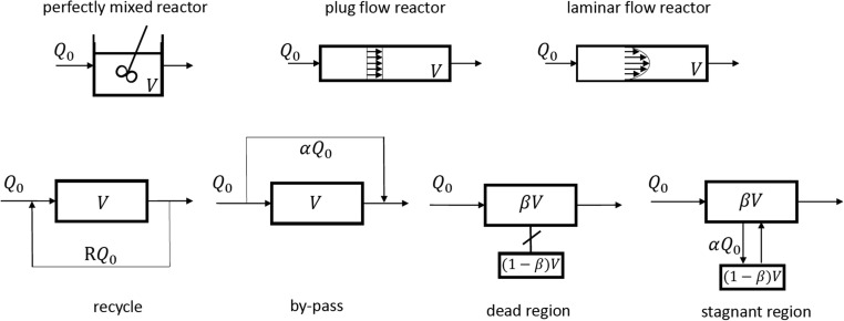
A class of models (compartment models) can be built by assembling nuclei elements in order to represent tracer experiments in real reactors. Those nuclei elements are: i) perfectly mixed reactor; ii) plug flow reactor; iii) laminar flow reactor, iv) recycle; v) by-pass or short-circuit; vi) dead zones and vii) stagnant zones. Nuclei-elements are shown in Fig. 5 .
Fig. 5.
Nuclei elements of compartment models.
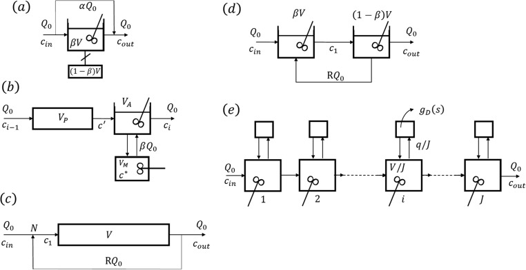
Typical models of this class such as Cholette and Cloutier (Cholette and Cloutier, 1959), Adler and Hovorka (Adler et al., 1961), plug flow with recycle (Villermaux, Lavoisier (1993).), tank in series with recycle (Levenspiel, 2012) and unified time delay model (Buffham and Gibilaro, 1970) are shown in Fig. 6 .
Fig. 6.
Examples of “complex” models: (a) Cholette and Cloutier, (b) Adler and Hovorka, (c) plug flow with recycle and (d) tanks in series with recycle and (e) unified time delay model.
(a) The Cholette and Cloutier model (Fig. 6a) of a stirred tank reactor with space time
considers a by-pass flowrate and a dead zone with volume ; the model has three parameters: . The transfer function is:
| (14) |
and the RTD is:
| (15) |
(b) The basic unit of the Adler and Hovorka model (Fig. 6b) of a real reactor is a cell with total volume and feed flowrate combining a plug flow reactor of volume and a perfectly mixed stirred tank of volume exchanging mass with a stagnant zone of volume . The flowrate exchanged is . The transfer function is now:
| (16) |
The model parameters are , and . For the model reduces to the Kramers system (plug flow and perfectly mixed reactor in series).
(c) The plug flow with recycle flowrate (Fig. 6c) is a good example of recirculation systems. The transfer function is:
| (17) |
and the RTD is a series of impulses with decreasing strength:
| (18) |
In the above equations R is the recycle ratio: ratio between the recycle flowrate (RQ0) and feed flowrate (Q0).
(d) The model of tanks in series with volumes and with recycle is shown in Fig. 6d. The system is a second-order system with dumping factor and a time constant where the space time of the reactor is . The RTD is now:
| (19) |
(e) The unified time delay model of a packed bed in its version of discrete cells in series is shown in Fig. 6e. The model parameters are the minimum transit time of a fluid element which is not delayed in the main flow region with volume and the mean delay time ( where is the lateral flowrate in each discrete cell) for a delay time distribution in lateral zones. The transfer function is:
| (20) |
where and is the transfer function of the lateral zone with an exponential time delay distribution .
A recent review on compartmental modeling can be find elsewhere (Jourdan et al., 2019).
3.2. Application to NETmix® reactor
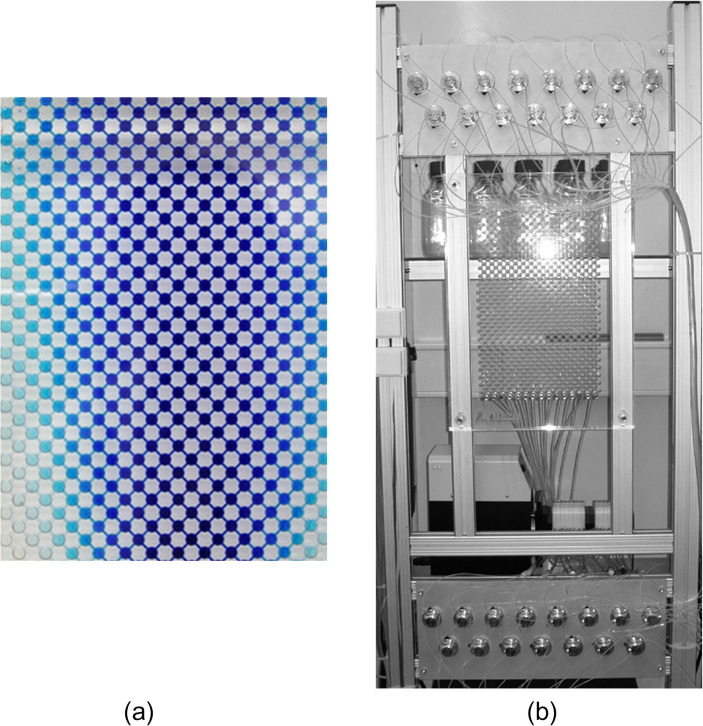
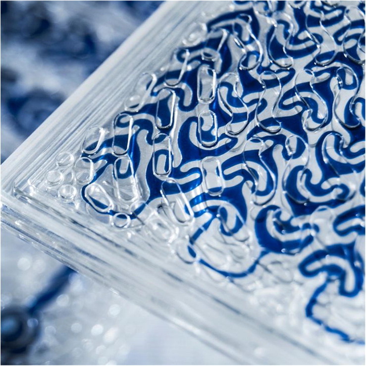
The NETmix® reactor is shown in Fig. 7 . It is a network of chambers connected by channels (Martins et al., 2007, Laranjeira et al., 2009). It is a technology for static mixing which has been patented (Lopes et al., 2004) and successfully used industrially for the production of hydroxyapatite nanoparticles (Silva et al., 2008, Gomes et al., 2009). The model assumes that the chambers are perfectly mixed reactors and the channels are plug flow systems. The RTD can be derived easily for such model
| (21) |
Fig. 7.
NETmix® reactor: (a) Network of channels and chambers and (b) photo of an industrial unit (www.fluidinova.com).
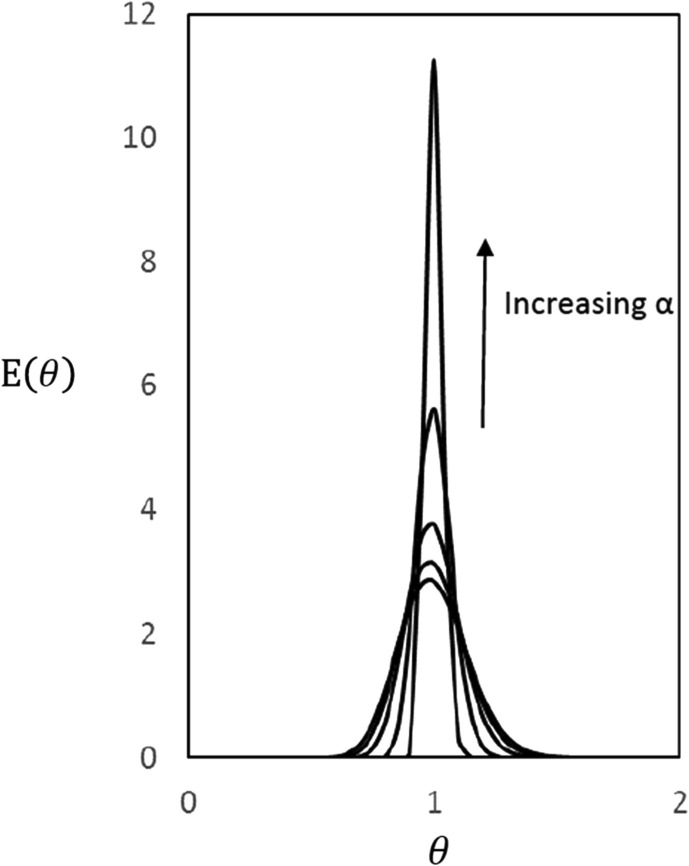
In Equation (21) the segregation parameter is and the network is an alternate sequence of piston flow channels and perfectly mixed chambers finishing with one piston flow channel at the exit; the normalized time is and the space time is the network volume divided by the total flowrate. Fig. 8 shows RTD of a Netmix reactor for and various values of the segregation parameter .
Fig. 8.
RTD for a Netmix reactor; nx = 50 number of piston flow channels and increasing from 0.01, 0.1, 0.25, 0.5 and 0.75 (reprinted from Laranjeira et al, AIChEJ, 55, 2226–2243 (2009), with permission from Wiley).
Advanced-FlowTM Reactors (AFR) from Corning (Suranani et al., 2018) have also been used in a number of applications from biodiesel to the production of Active Pharmaceutical Ingredients (APIs) in pharma industry. It is interesting to note the patented HEART design of the mixers elements ( Figure 9 ).
Fig. 9.
Advanced-FlowTM Reactors (AFR) from Corning.
3.3. Staged models and Standard dispersion model (SDM)
The more used models to describe fluid flow in packed bed columns are the staged model and the standard dispersion model (SDM) or plug dispersion flow model.
3.3.1. Staged model and the chromatography plate theory of Martin and Synge
One important application of the staged model was in the modeling of chromatographic processes - the Plate theory of Martin e Synge (Martin and Synge, 1941). The column is viewed as a cascade of J mixing cells in series each one containing a volume of fluid phase vf and a volume of solid phase vs; the space time is and the partition of solute between phases or capacity factor is where m is the slope of the adsorption equilibrium isotherm relating concentrations of solute in the solid and fluid phases at the interface. The retention time (first moment of the chromatographic peak) is then . The system transfer function is:
| (22) |
and the outlet normalized concentration is:
| (23) |
The moments of are , and the variance is ; the peak maximum is and the peak width at mid-height for high , is . In the case of homogeneous systems without adsorbent/catalyst particles and the first moment of is simply the space time . This result holds for the model of Mixing Cells in Cascade and to my knowledge was first reported by Mac Mullin and Weber (MacMullin and Weber, 1935) in 1935 although the title of that paper could be confusing.
The model above considers instantaneous equilibrium between the solute in fluid phase and in the adsorbed phase. We know that the behaviour of a fixed bed chromatographic or adsorption column is governed by equilibrium and kinetic factors (hydrodynamics, heat/mass transfer).
If we add a degree of complexity in the above model by considering a finite mass transfer rate between fluid and solid phases we have a new model MCE: Mixing cells in Cascade with Exchange (Villermaux, 1972). Model equations are the mass balance over a mixing cell, the kinetic law of mass transfer between phases and the equilibrium law at the interface:
| (24) |
| (25) |
| (26) |
where is the feed flowrate, is the fluid solute concentration, is the adsorbed phase concentration at the particle/fluid interface in equilibrium with , is the average particle concentration , is the particle specific area and is the mass transfer coefficient between bulk fluid and particle.
By putting the transfer function is:
| (27) |
The moments of the chromatographic peak are: and
3.3.2. Standard dispersion model (SDM)
The plug diffusional model or Standard Dispersion model (SDM) in its simple version superimposes plug flow and axial dispersion. From the second Fick’s law and considering a plane source of tracer with N moles/unit area in a quiescent medium we obtain:
| (28) |
In the above Eq. (28), c(z, t) is the concentration in axial direction z at time t and D is axial diffusion.
Now if the fluid is moving with velocity u in a tube with length L, the residence time distribution will be
| (29) |
where the concentration was normalized by , the dimensionless time is and the Peclet number is , based on the reactor length.
Alternatively one can start with the mass balance of tracer in a volume element of a bed with porosity ε packed with non-permeable particles showing the contribution of convection, accumulation and axial dispersion:
| (30) |
together with Danckwerts boundary conditions (which seems to be first suggested by Langmuir (Langmuir, 1908)
| (30a) |
| (30b) |
to get the RTD, Equation (29), where the space time is redefined as and .
The axial dispersion contains the contribution of molecular diffusion Dm and eddy dispersion due to the presence of the packing; at high Reynolds number the random walk theory of diffusion allows as to calculate Bodenstein numbers for axial and radial dispersion, .
For a packed bed with porous particles the mass balance for inert, passive tracer in a bed volume element is:
| (31) |
and at the particle level the mass balance writes as:
| (32) |
Obviously in a tracer experiment in a bed with porous particles what we are measuring is an “apparent axial dispersion”
| (33) |
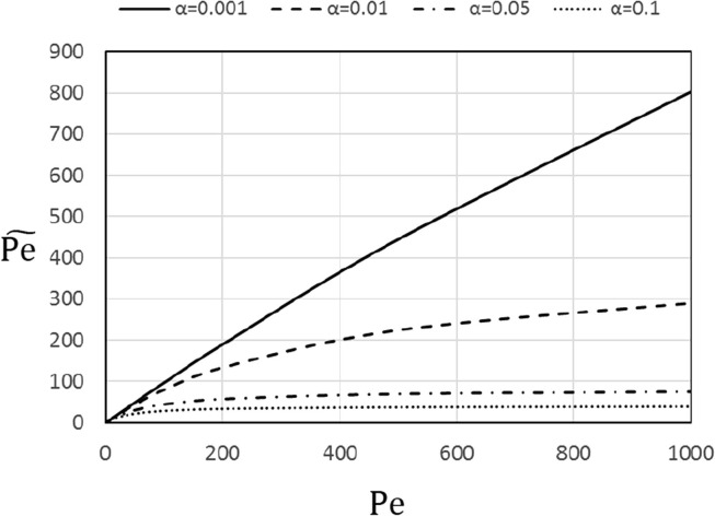
where the interstitial velocity is , the ratio of fluid in the particle pores and outside particles is and the intraparticle diffusion time constant is . Alternatively one can write a relation between the “apparent Peclet number” and :
| (33a) |
or
| (33b) |
where the parameter is the ratio of the time constants for diffusion and convection. Only when intraparticle diffusion is very fast and goes to zero we are measuring axial dispersion
free of intrusion of pore diffusion. This is illustrated in Fig. 10 showing the apparent Peclet number, versus .
Fig. 10.
Apparent Peclet number, versus Pe.
Van Deemter, Zuiderweg and Klinkenberg viewed the column as a continuous system (Van Deemter et al., 1956) with flow described by the plug dispersion model; for linear systems the transfer function is:
| (34) |
where . The variance is obtained by replacing by . The response to a step input of tracer is (Danckwerts, 1953)
| (35) |
Danckwerts used this result to experimentally show for the first time, according to Amundson (Amundson, 1986), that was close to 2.
3.3.2.1. Notes on boundary conditions for the Standard dispersion model (SDM)
The proper boundary conditions for the SDM have been discussed for a long time (Wehner and Wilhelm, 1956, Levenspiel and Smith, 1957, Brenner, 1962) since the publication of Danckwerts paper (Danckwerts, 1953) in 1953. The so-called Danckwerts boundary conditions given in Eqs 30a and 30b correspond to “closed-to-diffusion” boundaries. Other boundary conditions used for SDM are those of infinite reactor (open-to-diffusion), Eq 36a, semi-infinite reactor (open to diffusion at the inlet), Eq 36b and open-to-diffusion at the outlet, Eq 36c
| (36a) |
| (36b) |
| (36c) |
For practical purposes the RTDs from SDM for various types of boundary conditions are similar if Pe is sufficiently high. A detailed discussion of this topic for transient reactor was provided by Parulekar and Ramkrisna (Parulekar et al., 1982).
3.3.3. The Taylor-Aris model for flow in tubes
G. I. Taylor pioneer work describes how a solute travels in a capillary where a solvent is moving in laminar flow (Taylor, 1953). It seems, according to Batchelor (Batchelor, 1981) that “Taylor learnt about this problem from an animal physiologist who was measuring the rate of flow of blood in arteries by injecting a small volume of highly conducting liquid (tracer) at some point and measuring the change of conductivity with time at another point downstream”. Dispersion is an unsteady diffusion process characterized with an effective diffusion coefficient or dispersion coefficient which measures the rate at which the solute spreads axially and is proportional to the ratio axial convection/radial (transverse) molecular diffusion.
Fig. 11 shows the velocity profile, reference coordinates and band profiles of the solute at various times. The velocity in a channel with radius r0 for laminar flow is given by Eq (37) where u is the mean fluid velocity.
| (37) |
Fig. 11.
Velocity profile and dispersion of a slug in a tube.
At short times axial convection is the dominant mechanism and the slug of solute introduced at time zero takes the parabolic shape imposed by the velocity profile. This leads to radial concentration gradients and so at higher times radial molecular diffusion contributes to the dispersion process resulting in compression of the mixing zone. At longer times, where axial convection is important and radial (transverse) diffusion ≫ axial diffusion one can neglect axial concentration gradients if ≫1 (Peclet number ); this is the Taylor dispersion regime where the flow is quasi-steady relative to the axis moving at the mean fluid velocity.
The mass balance for the solute in a volume element of the tube is:
| (38) |
The boundary conditions are:
| (38a) |
| (38b) |
| (38c) |
| (38d) |
Changing the reference frame for moving with the mean fluid velocity , Eq (38) becomes
| (39) |
When axial diffusion is neglected compared to axial convection, the asymptotic behavior is reached for long-time distribution of the solute ,i.e., or allowing the quasi-steady state assumption and axial concentration gradient where is the area-averaged solute concentration. The concentration profile is:
| (39a) |
The area-averaged convective flux relative to the moving observer is:
| (40) |
and using eqs (39), (40) we get:
| (41) |
The Taylor dispersion coefficient is .
The 1D macrotransport equation in terms of the fixed reference frame z governing the area-averaged solute concentration is
| (42) |
where u*=u and the Taylor-Aris dispersion is the result obtained by Aris (Aris, 1956).
The validity of Taylor dispersion imposes or . In the region and where both radial and axial diffusion are important, .
The area-averaged concentration profile is:
| (43) |
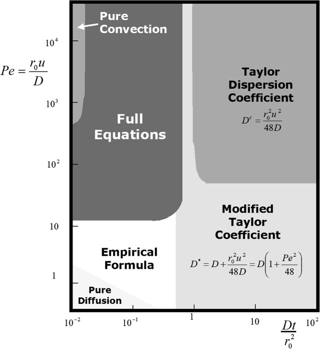
The limiting case of pure convection holds if the time constants for radial diffusion, and axial diffusion, are both higher than the convective time constant , i.e., and respectively. Similarly axial diffusion is controlling if or . These results are condensed in Fig. 12 adapted from Aris (Aris, 1994).
Fig. 12.
Dispersion of a solute in a tube: map of controlling mechanisms in terms of Peclet number, Pe vs dimensionless time (adapted from R. Aris, Mathematical modeling techniques, Dover, New York, 1994 with permission).
Taylor (Taylor, 1954) extended his approach to turbulent flow in tubes and provided conditions to use experiments of dispersion of solutes in a solvent flowing in a tube to measure molecular diffusion (Taylor, 1954). The Taylor-Aris method was used by Mc Calley (Mc Calley, 2002) to measure diffusion coefficients in monolith reversed-phase columns .
The Taylor description can be extended to include adsorption at the wall of the channels and diffusion at the wall surface ; in that case the zone migrates at a velocity:
| (44) |
and the effective diffusion coefficient will be given a form of Golay equation (Golay, 1968):
| (45) |
where is the adsorption equilibrium parameter for linear isotherms.
3.4. Progressive modeling and perfusion chromatography
The measurement of effective diffusivity in large pore catalysts can use a chromatographic method and tracer technology. The analysis of results (Ahn, 1980) with a conventional model showed that effective diffusivity was changing with flowrate. A closer look to the problem assuming mass transport not only by diffusion in pores but also by convection (pore velocity ) and the equivalence with the conventional model in which both mechanisms were lumped in an apparent allowed us to show (Rodrigues et al., 1982) that:
| (46) |
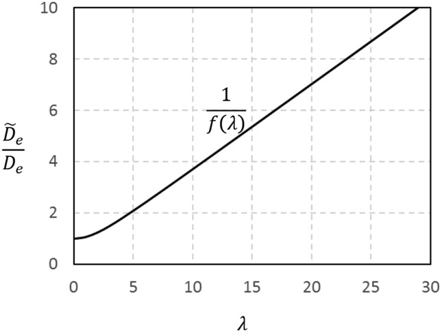
Here the intraparticle Peclet number is and . The apparent diffusivity is augmented by convection and the enhancement factor is . This result shown in Fig. 13 explains the functioning of perfusion chromatography (Afeyan et al., 1990, Afeyan et al., 1990, Afeyan et al., 1991, Rodrigues et al., 1991).
Fig. 13.
Enhancement factor for diffusivity due to convection in particle pores: versus λ.
For a passive tracer the “lumped” diffusion/convection model for the particle with slab geometry is:
| (47) |
and the particle transfer function is:
| (48) |
with an apparent diffusion time constant .
On the other hand the complete diffusion/convection model is:
| (49) |
and the transfer function is
| (50) |
with , where the diffusion time constant is .Model equivalence leads to Eq. (46)
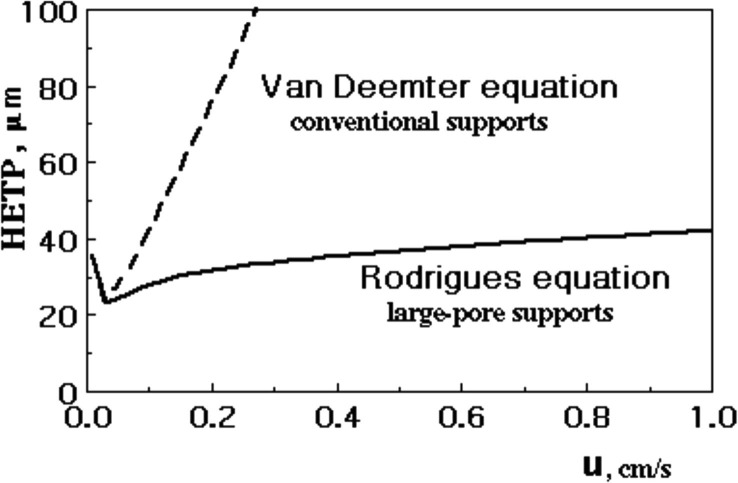
A practical application of this concept is on the chromatographic separation of proteins. The pore velocity can be estimated from the equality between relative pressure drop at bed and particle scales assuming that Darcy’s law is valid; the result is where is the ratio of particle and bed permeabilities. The Van Deemter equation for conventional packings was modified by Rodrigues (Rodrigues et al., 1991, Rodrigues, 1993) where the C term shows the effect of intraparticle convection.
| (51) |
Fig. 14 shows HETP versus u for conventional and perfusive adsorbents. At low velocities
Fig. 14.
HETP versus superficial velocity for conventional (Van Deemter equation) and large-pore supports (Rodrigues equation).
; however, at high velocities and the last term of Rodrigues equation (51) becomes constant. The HETP reaches a plateau which only depends on the particle permeability and pressure gradient (convection-controlled limit). The C term of Van Deemter equation is reduced, the column performance is improved and the speed of separation is increased without loosing efficiency.
4. Shortcoming of Standard dispersion model (SDM) and the Wave model
The SDM described by Eq (30) and Danckwerts boundary conditions, eqs (30a), (30b) has raised doubts concerning several points, which may be considered as drawbacks of the model. Westerterp (Westerterp, 2012) listed some of those concerns, namely:
-
i)
The basic idea of SDM is that axial dispersion is superimposed to plug flow; however plug flow means that radial dispersion is infinitely fast but in packed beds the Bodenstein number for radial dispersion is not zero;
-
ii)
The physical significance of boundary conditions has been questioned along the years (Petho and Noble, 1982). The inlet boundary condition means a sudden fall more pronounced for small Peclet numbers although this fall certainly happens in a perfectly mixed reactor by definition;
-
iii)
In packed beds backmixing can occur as shown by Hiby (Hiby, 1962) but does not exist in 1D flow;
-
iv)
As pointed out in 1962 by Westerterp (Westerperp and Landsman, 1962, Westerperp and Meyberg, 1962) axial dispersion under the same flow conditions depends on the measurement technique; also Jasti and Fogler (Jasti and Fogler, 1992) noticed that Dax was influenced by flow reversal;
-
v)
Laminar flow can not be handled by the SDM
In the “Wave Model” axial dispersion results from the fact that fluid velocity in axial direction is not uniform. It means that some fluid streams travel at velocity u + v higher than the average velocity u, while others travel at velocity u-v lower than the average velocity as shown in a simplistic way in Fig. 15 .
Fig. 15.
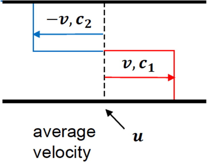
Velocity profile in a tubular reactor around average velocity and scheme for fluid into two equal sections with velocities and and concentrations and .
Assuming no chemical reaction and equal cross section areas occupied by both streams mass balances for each stream are:
| (52a) |
| (52b) |
where k is the exchange coefficient between both streams (relaxation time constant) expressed in sec -1.
The average concentration c and the dispersion flux jd are given by c=(c1 + c2)/2 and jd = v(c1-c2)/2, respectively; the conservation equation for mass becomes:
| (53) |
with the dispersion flux satisfying
| (54) |
where and .
The initial and boundary conditions are now:
| (54a) |
| (54b) |
Instead of one parameter in SDM, there is now one more parameter, the relaxation time constant .
It is important to notice that the basic laws of momentum transfer (Newton’s law), mass transfer by diffusion (Fick’s law) and heat conduction (Fourier’s law) assume infinite velocity of propagation of signals; this problem is eliminated in Maxwell formulation for momentum transfer (Maxwell, 1952), mass transfer by diffusion (Rodrigues and Minceva, 2005) and heat transfer (Liu et al., 1999). For mass transfer in quiescent media we have a description similar to Cattaneo (Cattaneo, 1958) equation for heat transfer by conduction (Turner, 1972).
| (55) |
It is also interesting to note that the transfer function of the fixed bed in the case of the Wave Model becomes:
| (56) |
Again the SDM is recovered when . The transfer function of the wave model is obtained simply from the one of SDM model by replacing by . The SDM model will be applicable when .
The relationship between the wave (relaxation) model and diffusion model of longitudinal dispersion accompanied by chemical reaction was discussed by Moshinskii (Moshinskii, 2003). Also Iordanidis et al (Iordanidis et al., 2003) critically compared the wave model and the standard dispersion model for various exothermic reactions and concluded that the main difference is in the description of energy transport; discrepancies are more significant for fast processes with steep temperature and concentration profiles along the reactor.
5. RTD calculations from momentum and mass transport equations and CFD modeling
Levenspiel (Levenspiel, 2002) summarizes the progress on the study of fluid flow as follows: “In the 19th century there were two approaches to study fluid flow: hydrodynamics (dealt with ideal frictionless fluid; highly mathematical stuff) and hydraulics developed by civil engineers “ who amassed mountains of tables of pressure drop and head loss of fluids in open and closed channels of all sort…”. At the beginning of the 20th century Prandtl said “Hydrodynamics has little significance for the engineer because of the great mathematical knowledge required for an understanding of it and the negligible possibility of applying its results. Therefore engineers put their trust in the mass of empirical data collectively known as the “science of hydraulics”. “Prandtl was the genius who patched together these different disciplines with his simple boundary layer theory. The result is modern fluid mechanics”. Although this view is shared by some authors (Anderson, 2010), others associate L-Prandtl and G.I.Taylor (Kundu and Ira, 2000, Batchelor, 1992) as founders of modern fluid mechanics.
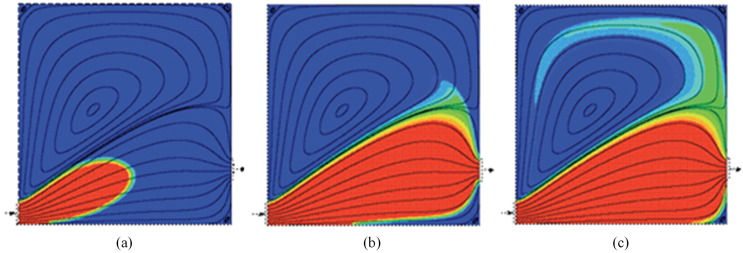
On the other hand numerical methods for the solution of PDE’s exist and the combination of two solid disciplines appears with a new name: “Computational Fluid Dynamics”. As Krishna said once in a CHEMPOR meeting in Lisbon (Krishna, 1998) CFD results from Numerical Methods and Fluid Mechanics using computers. More than thirty years ago, I published (Brunier et al., 1984) a paper with French colleagues in ISCRE8: “Residence time distribution in laminar flow through reservoirs from momentum and mass transport equations”. It is a problem of 2-D flow in a reservoir of length L and height H where a stationary laminar flow exists between inlet and outlet. The model equations include momentum transport under steady state condition in terms of vorticity and stream function formulation; the flow field is obtained and the tracer mass transport is described by a convection–diffusion equation leading to the RTD:
| (57) |
| (58) |
| (59) |
| (60) |
Eq. (57), (58), (59), (60) were solved for and together with appropriate boundary conditions. At the inlet a parabolic profile was imposed and the flowrate through the reservoir is and the mean residence time is where is a flowrate parameter and e is the depth of the reservoir. This problem was solved later with modern tools (Fluent) (Madeira et al., 2004). It is much better to visualize the movement of the tracer inside the reactor (http://paginas.fe.up.pt/~mmalves/cfd/reactor/index.htm) although the information contained in or internal age distribution is the same as in the “old” time. Fig. 16 shows the tracer concentration evolution in a tank full of water for and at different dimensinless times normalized by the space time. The black lines shown are the streamlines. It is a 1000 $ model if I extend the classification of Levenspiel (Levenspiel, 2002) of 10$ and 100$ models (at least in terms of computer cost!),
Fig. 16.
Tracer concentration evolution in a 2-D flow in a reservoir at various dimensionless times (a) t/τ = 0.1 (b) t/τ = 1 (c) t/τ = 5 (https://web.fe.up.pt/~mmalves/cfd/reactor/pictures.htm).
6. How to access age distribution and state of mixing, smart RTD and future challenges
6.1. Spatial distribution of internal age a(x,t) and Smart RTD
The exit concentration of a reactor can in general be obtained by solving the equations for flow and tracer mass balance; for incompressible flows they are:
| (61) |
| (62) |
From equation (61) we can get the spatial distribution of the mean age (averaged over time locally) a(x) under steady flow (Spalding, 1958, Danckwerts, 1958). More interesting is to obtain the spatial distribution of the instantaneous fluid particle age a(x,t) as introduced by Sandberg (1981). The balance of the fluid age is then
| (63) |
This was called by Simcik et al (Simcik et al., 2012) the Smart RTD (SRTD). While RTD only gives the distribution of the internal age for steady flow, the SRTD gives the space–time distribution of the instantaneous fluid age a(x,t) for unsteady state flow in general. This approach was also discussed by Liu and Tilton (Liu and Tilton, 2010), Baléo and Le Cloirec (Baléo and Le Cloirec, 2000) and Liu (Liu, 2011) who performed 2D simulations in a single phase reactor.
The mean age is the first moment of age calculated as:
| (64) |
The denominator is invariant and equal to the ratio of the total amount of tracer in the pulse to the volumetric flowrate. Liu presented a method to predict the tracer concentration and mixing in CFSTRs with mean age distribution (Liu, 2011). The mean age theory was extended to multiphase systems by Russ and Berson (Russ and Berson, 2016). CFD solutions of mean age allow spatial and time resolution within the flow field.
The study of mixing processes needs somehow a parameter to quantify the “goodness of mixing” based on experimental measurements (Zwietering, 1959, Danckwerts, 1952, Danckwerts, 1958). Liu (Liu, 2011) presented a method for the calculation of the degree of mixing in steady continuous flow systems. The age α of a molecule is the time that has elapsed since the molecule entered the reactor; the average age of all molecules in the flow is . The variance of the ages of all molecules will be:
| (65) |
and the variance of mean age all over the whole reactor volume is
| (66) |
The degree of mixing of Zwietering (Zwietering, 1959) was defined as
| (67) |
Therefore from RTD one calculate the distribution of internal ages, and obtain the variance of the ages of all molecules var . However, to get one still needs the spatial distribution of mean age to calculate the variance of mean age var a. In a CSTR the variance of mean age is zero and ; for completely segregated system . The calculation of the degree of mixing was possible with the work of Liu and Tilton (Liu and Tilton, 2010) who derived the governing equations for all moments of age from the time dependent concentration equation and equation for the mean age
| (68) |
| (69) |
leading to
| (70) |
where is the nth moment of age calculated from the tracer concentration at every spatial position x:
| (71) |
The Zwietering degree of mixing can now be written as
| (72) |
CFD is a powerful tool to help process development in chemical engineering and examples in stirred tanks and static mixers have been discussed by LaRoche (LaRoche, 2005), Liu (Liu, 2012), Khapre et al. (Khapre et al., 2016). One example at hand is the study of mixing and its mechanisms addressed in detail in the book by Ottino (Ottino, 1989). It is interesting to learn that in a note published in 1987 by Franjione and Ottino (Franjione and Ottino, 1987) they presented some calculations showing that numerical tracking of the interface in mixing involving fast reactions between fluids was an enormous task with the computing power at the time. Recently, Matos et al (Matos et al., 2018) introduced a new method Lagrangian Mixing Simulation (LMS) to track the flow front between two fluids in a mixer. LMS uses Eulerian velocity field from CFD simulations to calculate the instantaneous rate of interfacial area generation and segregation scales and it was applied to CFD simulations of flow in 2D Confined Impinging Jets (Fig. 17 ).
Fig. 17.
Flow tracking by Lagrangian mixing simulation (Reprinted from Matos et al, Chem. Eng. Sci., 192, 199–210 (2018) with permission from Elsevier).
6.2. Looking ahead
The concept of RTD is spread through many areas from solid processing (continuous blenders, extruders, rotary drums, fluidized beds) used in continuous manufacturing of chemicals, plastics, polymers, food, catalysts and pharmaceutical products (Gao et al., 2012), to hydrodynamic modeling of real systems (liquid–liquid systems (Nogueira et al., 2016), simulated moving bed (Fangueiro Gomes et al., 2015, Fangueiro Gomes et al., 2016), cascades of stirred tanks (Toson et al., 2019), continuous flow polymerization (Reis et al., 2019).
Tracer technology (Levenspiel, 2012, Aris, 1994, Wei, 1990) has many applications outside the traditional chemical engineering (Shook, 2005) and extensions of the traditional RTD have appeared, (Claudel et al., 2000, Dantas et al., 2014, Morscheidt et al., 2013) and still experimental improvements are reported (Bérard et al., 2020).
The recent push of continuous flow chemistry in pharmaceutical industry and the development of milli-and microreactors renewed the interest on RTD for the characterization of the flow behavior in such devices (Gobert et al., 2017, Siguemoto et al., 2020).
I am particularly interested in less conventional applications of RTD theory. I will mention two topics. One of those areas is Perfume Engineering (Teixeira et al., 2013) with the aim of predicting the trail of perfumes or sillage (Pereira et al., 2018, Benaim and Brahms, 2018). Briefly a perfume is commonly viewed as a mixture of top notes, middle notes and base notes in a solvent. Some perfumers will say there are no middle notes and what matters is the diffusivity of top and base notes containing fast and slow diffusing molecules (Benaim and Brahms, 2018). Therefore measurements of diffusivities of perfumery raw materials (PRM) in air are required to address the effect of molecule (Tovar et al., 2019) and skin adsorption.
A second area is related to archeology concerning the application of diffusion-adsorption-decay models for dating bones (Sambridge et al., 2012). But in our everyday life the measurement of RTD is routinely made in our main research activity on Cyclic separation/reaction processes.
Declaration of Competing Interest
The authors declare that they have no known competing financial interests or personal relationships that could have appeared to influence the work reported in this paper.
Acknowledgments
Acknowledgment
This work was financially supported by: Base Funding - UIDB/50020/2020 of the Associate Laboratory LSRE-LCM - funded by national funds through FCT/MCTES (PIDDAC).
Part of the manuscript was written at LPA of UFC (Brazil) as a Visiting Researcher of the program “Ciência sem Fronteiras”.
The help of Dr Elson Gomes and Dr Rui Faria with the preparation of figures is gratefully acknowledged.
References
- Villermaux J. Course Notes; ENSIC: 1972. Introduction a la Théorie des Réacteurs Chimiques. [Google Scholar]
- Levenspiel O. Seminar at the Center for Physical and Chemical kinetics of CNRS; Nancy: 1973. Tracer methods and flow modeling in chemical engineering. [Google Scholar]
- Levenspiel O. second ed. Wiley; 1972. Chemical reaction Engineering. [Google Scholar]
- Prandtl L. On fluid motions with very small friction. Third International Mathematical Congress, Heidelberg. 1904:484–491. [Google Scholar]
- Danckwerts P.V. Continuous flow systems. Distribution of residence times. Chem. Eng. Sci. 1953;2(1):1–13. [Google Scholar]
- Varey P. Life on the edge: Peter Danckwerts GC MBE FRS brave, shy, brilliant. PFV Publications. 2012 [Google Scholar]
- Danckwerts, P.V. “The challenges of Chemical Engineering Science”, Chapter 3, pg 48-58 in “Research and Innovation for the 1990s.The Chemical Engineering Challenge”, edited by B. Atkinson, The Institution of Chemical Engineers (1986)
- Brunier, E., Zoulalian, A. Antonini, G. and Rodrigues, A. E., “Residence time distributions in laminar flow through reservoirs from momentum and mass transport equations”, ISCRE 8, IChemE Symposium Series No 87, 439-446 (1984)
- Nauman E.B., Buffham B.A. Wiley; 1983. Mixing in continuous flow systems. [Google Scholar]
- Madeira, L.M., Alves, M. and Rodrigues, A.E. “ Teaching non-ideal reactors with CFD tools”, Chem Eng Educ 38 (2) 154-160 (2004); https://web.fe.up.pt/~mmalves/cfd/reactor/pictures.htm
- Westerterp, K., Dil’man,V., Kronberg, A. and Benneker, A. “Wave model for Longitudinal dispersion : development of the model”, AIChEJ, 41, 2013 (1995)
- Westerterp, K., Dil’man,V., Kronberg, A. and Benneker, A. “Wave model for Longitudinal dispersion : analysis and applications”, AIChEJ, 41, 2029 (1995)
- Kronberg A., Benneker A., Westerterp K. Wave model for Longitudinal dispersion : development of the model application to the laminar flow tubular reactor. AIChEJ. 1996;42:3133. [Google Scholar]
- Westerterp, K., Kronberg , A., Benneker, A. and Dil’man,V. “Wave concept in the theory of hydrodynamical dispersion:a Maxwellian approach “, Trans Inst Chem Eng A74, 944 (1996)
- Benneker A., Kronberg A., Westerterp K. Longitudinal mass and heat dispersion in tubular reactors. Ind. Eng. Chem. Res. 1997;36:2031–2040. [Google Scholar]
- Westerterp K. Presentation to the members of WP CRE of EFChE. ISCRE. 2012;22:Maastricht. [Google Scholar]
- Liu M. Age distribution and the degree of mixing in continuous flow stirred tank reactors. Chem. Eng. Sci. 2012;69:382–433. [Google Scholar]
- Liu M. Prediction of tracer concentration and mixing in CFSTRs with mean Age distribution. Ind. Eng. Chem. Res. 2011;50:5838–5851. [Google Scholar]
- Liu M. A method for computing the degree of mixing in steady continuous flow systems. Chem. Eng. Sci. 2011;66:3045–3048. [Google Scholar]
- Liu M., Tilton J. Spacial distributions of mean age and higher moments in steady continuos flows. AIChEJ. 2010;56:2561–2572. [Google Scholar]
- Liu M. Quantitative characterization of mixing in stirred tank reactors with mean age distribution. Can. J. Chem. Eng. 2011;89:1018–1028. [Google Scholar]
- Levenspiel O., Bischoff K. Patterns of flow in chemical process vessels. Adv. Chem. Eng. 1963;4:95. [Google Scholar]
- Shinnar R. Levich conference; Oxford: 1977. Tracer experiments in chemical reactor design. [Google Scholar]
- Weinstein H., Dudukovic M. Halsted Press; Gutfinger: 1975. “Tracer methods in the circulation” in Topics in Transport Phenomena ed C. [Google Scholar]
- Zvirin Y., Shinnar R. A comparison of lumped-parameter and diffusional models describing the effects of the outlet boundary conditions on the mixing in flow systems. Water Res. 1976;10:765–779. [Google Scholar]
- Angelo, M. J. “Development and applications of pharmacokinetics models”, Seminar at University of Virginia, April 28 (1988)
- Rodrigues, A.E. “Theory of residence time distributions”, in Multiphase Reactors Vol 1 Fundamentals, edited by A. E. Rodrigues, J. Calo and N. Sweed , Sijthoff & Noordhoff (1981)
- Van der Laan E. Notes on the diffusion-type model for the longitudinal mixing in flow. Chem. Eng. Sci. 1958;7:187. [Google Scholar]
- Zwietering Th. The degree of mixing in continuous flow systems. Chem. Eng. Sci. 1959;11(19):1. [Google Scholar]
- Bérard A., Blais B., Patience G.S. Experimental methods in chemical engineering: residence time distribution-RTD. Can. J. Chem. Eng. 2020;98:848–867. [Google Scholar]
- Sheoran M., Chandra A., Bhunia H., Pramod K. residence time distribution studies using radiotracers in chemical industry-A review. Chem Eng Comm. 2018;205:739–758. [Google Scholar]
- Radiotracer residence time distribution method for industrial and environmental applications, Material for education and on-the-job training for practitioners of radiotracer technology, Training Course Series 31, IAEA, Vienna (2008).
- Martin A.D. Interpretation of residence time distribution data. Chem. Eng. Sci. 2000;55:5907–5917. [Google Scholar]
- Leclerc, J.P., Claudel, S., Lintz, H.G., Potier, O and Antoine,B.,”Theoretical interpretation of residence time distribution measurements in industrial processes”, Oil&Gas Science and Technology- Rev. IFP, 55(2),159-169 (2000)
- Cholette A., Cloutier L. Mixing efficiency determination for continuous flow systems. Can. J. Chem. Eng. 1959;37:105–112. [Google Scholar]
- Adler, R.J. and Hovorka, R.B., Preprint 3, Second Joint Automatic Control Conference, Denver, Colorado, June (1961)
- Villermaux, J., Génie de la Réaction Chimique, 2nd edition, Lavoisier (1993)
- Levenspiel O. Modeling the flow of fluids. Springer; 2012. Tracer methodology. [Google Scholar]
- Buffham B.A., Gibilaro L.G. A unified time delay model for dispersion in flowing media. The Chem Eng J. 1970;1:31–36. [Google Scholar]
- Jourdan N., Neveux T., Potier O., Kanniche M., Wicks J., Nopens I., Rehman U., Le Moullec Y. Compartmental modeling in chemical engineering: a critical review. Chem. Eng. Sci. 2019;210 [Google Scholar]
- Martins A.A., Laranjeira P.E., Lopes J.C.B., Dias M.M. Network modeling of flow in a packed bed. AIChE J. 2007;53:91–107. [Google Scholar]
- Laranjeira P.E., Martins A.A., Lopes J.C.B., Dias M.M. Netmix, a new type of static mixer: modeling, simulation, macromixing and micromixing characterization. AIChEJ. 2009;55:2226–2243. [Google Scholar]
- Lopes, J.C.B., Laranjeira, P.E., Dias, M.M. and Martins, A.A. “Network mixer and related mixing process”, PCT/IB2005/000647,2004, EP172643,2008; US8434933,2013
- Silva V.M.T.M., Quadros P.A., Laranjeira P.E., Dias M.M., Lopes J.C.B. A novel continuous industrial process for producing hydroxyapatite nanoparticles. J. Dispersion Sci. Technol. 2008;29:542–547. [Google Scholar]
- Gomes P.J., Silva V.M.T.M., Quadros P.A., Dias M.M., Lopes J.C.B. A Highly Reproducible Continuous Process for Hydroxyapatite Nanoparticles Synthesis. J. Nanosci. Nanotechnol. 2009;9(6):3387–3395. doi: 10.1166/jnn.2009.ns06. [DOI] [PubMed] [Google Scholar]
- Suranani S., Maralla Y., Gaikwad S.M., Sonawane S.H. Process intensification using corning advanced-flow™reactor for continuous flow synthesis of biodiesel from fresh oil and used cooking oil. Chem. Eng. Process.-Process Intensificat. 2018;126:62–73. [Google Scholar]
- Martin A.J.P., Synge A.L.M. A new form of chromatogram employing two liquid phases. Biochem. J. 1941;35:1358–1368. doi: 10.1042/bj0351358. [DOI] [PMC free article] [PubMed] [Google Scholar]
- MacMullin R.B., Weber M. The Theory of Short-Circuiting in Continuous-Flow Mixing Vessels in Series and Kinetics of Chemical Reactions in Such Systems. Trans. AIChE. 1935;31(2):409–458. [Google Scholar]
- Villermaux J. Analyse des processus chromatographiques linéaires à l'aide de modèles phénomélogiques. Chem. Eng. Sci. 1972;27:1231–1241. [Google Scholar]
- Langmuir I. The velocities of reactions in gases moving through heated vessels and the effect of convection and diffusion. J. Am. Chem. Soc. 1908;30:1742–1754. [Google Scholar]
- Van Deemter J., Zuiderweg F., Klinkenberg A. Longitudinal diffusion and resistance to mass transfer as causes of nonideality in chromatography. Chem. Eng. Sci. 1956;5:271–289. [Google Scholar]
- Amundson N.R. P.V. Danckwerts-his research career and its significance. Chem. Eng. Sci. 1986;41(8):1947–1955. [Google Scholar]
- Wehner J.F., Wilhelm R.H. Boundary conditions of flow reactor. Chem. Eng. Sci. 1956;6:89–93. [Google Scholar]
- Levenspiel O., Smith W.K. “Notes on the diffusion-type model for the longitudinal mixing of fluids in flow. Chem. Eng. Sci. 1957;6(4/5):227–235. [Google Scholar]
- Brenner H. The diffusion model of longitudinal mixing in beds of finite length. Numerical values. Chem. Eng. Sci. 1962;17(4):229–243. [Google Scholar]
- Parulekar, S.J. and Ramkrishna, D.,”A spectral-theoretic view of axial dispersion models”, in Residence time distribution theory in chemical engineering, ed. By A.Petho and R.D. Noble,pp 113-146, Verlag Chemie (1982)
- Taylor G. Dispersion of soluble matter in solvent flowing slowly through a tube. Proc. Roy. Soc. London. 1953;A219:186–203. [Google Scholar]
- Batchelor G.K. Preoccupations of a journal editor. J. Fluid Mech. 1981;106:1–25. [Google Scholar]
- Aris R. On the dispersion of solute in a fluid flowing through a tube. Proc. Roy. Soc. London. 1956;235A:67. [Google Scholar]
- Aris R. Dover; New York: 1994. Mathematical modeling techniques. [Google Scholar]
- Taylor G. The dispersion of matter in turbulent flow through a pipe. Proc. Roy. Soc. London. 1954;A223:446–468. [Google Scholar]
- Taylor G. Conditions under which dispersion of a solute in a stream of solvent can be used to measure molecular diffusion. Proc. Roy. Soc. London, A. 1954;225:473–477. [Google Scholar]
- Mc Calley D.V. Comparison of conventional microparticulate and a monolithic reversed-phase column for high-efficiency fastliquid chromatography of basic compounds. J. Chromatography A. 2002;965:51–64. doi: 10.1016/s0021-9673(01)01584-9. [DOI] [PubMed] [Google Scholar]
- Golay M.J.E. Height equivalent to a theoretical plate of an open tubular column lined with a porous layer: a generalized equation. Anal. Chem. 1968;40:382–384. [Google Scholar]
- Ahn B. Université de Technologie de Compiègne; 1980. Études des Caracteristiques Diffusionelles de Transfer de Matière dans un Reacteur Catalytique à Lit Fixe d'Oxidation Menagée. Ph.D. Thesis. [Google Scholar]
- Rodrigues, A.E., Ahn, B. and Zoulalian, A., 1982, 'Intraparticle forced convection effect in catalyst diffusivity measurements and reactor design', AIChE J., 28, 925-930 (1982)
- Afeyan N., Fulton S., Gordon N., Mazsaroff I., Varady L., Regnier F. Perfusion chromatography: an approach to purifying macromolecules. Nat. Biotechnol. 1990;8:203–206. [Google Scholar]
- Afeyan N., Gordon N., Mazsaroff I. Flow through particles for the high-performance liquid chromatography separation of bio-macromolecules. J. of Chromatography. 1990;519:1–29. doi: 10.1016/0021-9673(90)85132-f. [DOI] [PubMed] [Google Scholar]
- Rodrigues A.E., Loureiro J.M., Quinta Ferreira R.M. Intraparticle Convection Revisited. Chem. Eng. Commun. 1991;107:21–33. [Google Scholar]
- Afeyan, N., Regnier, F. and Dean Jr, R. “Perfusive chromatography”, US Patent 5019270 May 28 (1991)
- Rodrigues A.E., Lu Z.P., Loureiro J.M. Residence time distribution of inert and linearly adsorbed species in fixed-bed containing large-pore supports: applications in separation engineering. Chem. Eng. Sci. 1991;46:2765–2773. [Google Scholar]
- Rodrigues A.E. An extended Van Deemter equation (Rodrigues equation) for performing chromatographic processes using large-pore, permeable packings. LC-GC. 1993;6(1):20–29. [Google Scholar]
- Petho, A. and Noble, R.D. editors, “Residence Time Distribution in chemical engineering”, Verlag-Chemie (1982)
- Hiby, J.W. “Longitudinal and transverse mixing during single-phase flow through granular beds”. In Interaction between fluid and particles, London IChemE, 312-325 (1962)
- Westerperp K., Landsman P. Axial mixing in a rotating disk contactor- I Apparent Longitudinal Diffusion. Chem. Eng. Sci. 1962;17(5):363–372. [Google Scholar]
- Westerperp K., Meyberg W. Axial mixing in a rotating disk contactor- II Backmixing. Chem. Eng. Sci. 1962;17(5):373–377. [Google Scholar]
- Jasti J.K., Fogler H.S. Application of neutron radiography to image flow phenomena in porous media. AIChEJ. 1992;38(4):481–488. [Google Scholar]
- Maxwell J.C. Dover; New York: 1952. The scientific papers of James Clerk Maxwell. [Google Scholar]
- Rodrigues A.E., Minceva M. Modeling and simulation in chemical engineering: tools for process innovation. Comput. Chem. Eng. 2005;29:1167–1183. [Google Scholar]
- Liu J., Chen Xu., Xu L.X. New thermal wave aspects on burn evaluation of skin subjected to instantaneous heating. IEEE Trans. Biomed. Eng. 1999;46(4):420. doi: 10.1109/10.752939. [DOI] [PubMed] [Google Scholar]
- Cattaneo M.C. Sur une forme de l’equation de la chaleur limitant le paradoxe d’une propagation instantané. Comptes Rendues de L’Academie des Sciences: Series I- Mathematics. 1958;247:431–433. [Google Scholar]
- Turner G.A. Academic Press; 1972. Heat and concentration waves. [Google Scholar]
- Moshinskii A.I. Limiting cases of the equations of the wave model of longitudinal dispersion accompanied by a chemical reaction. Theor. Found. Chem. Eng. 2003;37(3):268–275. [Google Scholar]
- Iordanidis A., van Sint Annaland M., Kronberg A.E., Kuipers J.A.M. A critical comparison of the wave model and the standard dispersion model. Chem. Eng. Sci. 2003;58:2785–2795. [Google Scholar]
- Levenspiel O. Modeling in chemical engineering. Chem. Eng. Sci. 2002;57:4691–4696. [Google Scholar]
- Anderson J.D., Jr . Wiley; By Richard Blockley and Wei Shyy: 2010. “Brief history of the early development of theoretical and experimental fluid dynamics”, in Encyclopedia of Aerospace Engineering, ed. [Google Scholar]
- Kundu P.K., Ira M. second Ed. Academic Press; 2000. Cohen, Fluid Mechanics. [Google Scholar]
- G. Batchelor, Fifty years with fluid mechanics, Keynot paper K4, 11th Australian Fluid Mechanics Conderence, University of Tasmania, Hobart, Australia, 14-18 December (1992)
- Krishna , R. “Can CFD provide new insight in Chemical Engineering Science?” , Plenary lecture, CHEMPOR’98, Lisbon (1998).
- Spalding D.B. A note on mean residence times in steady flows of arbitrary complexity. Chem. Eng. Sci. 1958;9:74–77. [Google Scholar]
- Danckwerts P.V. Local residence times in continuous flow systems. Chem. Eng. Science. 1958;9:78–79. [Google Scholar]
- Sandberg M. What is ventilation efficiency. Build. Environ. 1981;16(2):123–155. [Google Scholar]
- Simcik M., Ruzicka M., Mota A., Teixeira J. Smart RTD for multiphase flow systems. ChERD. 2012;90:1739–1749. [Google Scholar]
- Baléo J.N., Le Cloirec P. Validating a prediction method of mean residence time spatial distributions. AIChEJ. 2000;46:675–683. [Google Scholar]
- Russ D.C., Berson R.E. Mean age theory in multiphase systems. Chem. Eng. Science. 2016;141:1–7. [Google Scholar]
- Danckwerts P.V. The definition and measurement of some characteristics of mixtures. Appl. Sci. Res. 1952;3:279–296. [Google Scholar]
- Danckwerts P.V. The effect of incomplete mixing on homogeneous reactions. Chem. Eng. Sci. 1958;8:93–102. [Google Scholar]
- LaRoche R.D. Lecture at CFD in Chemical Reaction Engineering IV; Barga, Italy: 2005. Evolution of CFD as a tool for chemical engineering. [Google Scholar]
- Khapre A., Rajavathsavai D., Munshi B. Study on residence time distribution of CSTR using CFD. Indian J. Chem. Technol. 2016;23:114–120. [Google Scholar]
- Ottino J.M. Cambridge University Press; 1989. The Kinematics of Mixing. Stretching, Chaos, and Transport. [Google Scholar]
- Franjione J.G., Ottino J.M. Feasibility of numerical tracking of material lines and surfaces in chaotic flows. Phys. Fluids. 1987;30(12):3641–3643. [Google Scholar]
- Matos J., Brito M.S.C.A., Dias M.M., Lopes J.C.B., Santos R.J. Lagrangian mixing simulation and quantification of scales. Chem. Eng. Science. 2018;192:199–210. [Google Scholar]
- Gao Y., Muzzio F.J., Ierapetritou M.G. A review of the Residence Time Distribution (RTD) applications in solid unit operations. Powder Technol. 2012;228:416–423. [Google Scholar]
- Nogueira A., Silva D., Baptista C.M.S.G. Modeling real flow in a continuous liquid-liquid system. Ind. Eng. Chem. Res. 2016;55(1):71–79. [Google Scholar]
- Fangueiro Gomes L., Augier F., Leinekugel-le-Cocq D., Vinkovic I., Simoens S. Hydrodynamic modeling of complex fluid geometries in simulated moving bed adsorption processes. Chem. Eng. Science. 2015;132:46–58. [Google Scholar]
- Fangueiro Gomes L., Augier F., Leinekugel-le-Cocq D., Vinkovic I., Simoens S. Modeling of a simulated moving bed in case of non-ideal hydrodynamics. Chem. Eng. Science. 2016;153:188–198. [Google Scholar]
- Toson P., Doshi P., Jajcevic D. Explicit Residence Time Distribution of a Generalised Cascade of Continuous Stirred Tank Reactors for a Description of Short Recirculation Time (Bypassing) Processes. 2019;7:615. doi: 10.3390/pr7090615. [DOI] [Google Scholar]
- Qamar S, Seidel-Morgenstern Andreas. Extending the potential of moments analysis in chromatography. Trends in Analytical Chemistry. 2016;81:87–101. [Google Scholar]
- Reis M.H., Varner T.P., Leibfarth F.A. The Influence of Residence Time Distribution on Continuous-Flow Polymerization. Macromolecules. 2019;52(9):3551–3557. [Google Scholar]
- Wei J. New horizons in reaction engineering. Chem. Eng. Sci. 1990;45(8):1947–1952. [Google Scholar]
- Shook G.M. Stanford University; 2005. “A systematic method for tracer test analysis: an example using Beowave tracer data” in Proceedings Thirtieth Workshop on Geothermal Reservoir Engineering. [Google Scholar]
- Claudel S., Leclerc J.P., Tétar L., Lintz H.G., Bernard A. Recent extensions of the residence time distribution concept: unsteady state conditions and hydrodynamic model developments. Braz. J. Chem. Eng. 2000;17(4–7):1–9. [Google Scholar]
- Dantas J.A.T.A., Pegoraro P.R., Gut J.A.W. Determination of the effective radial mass diffusivity in tubular reactors under non-newtonian laminar flow using residence time distribution data. Chem. Eng. Sci. 2014;71:18–25. [Google Scholar]
- Morscheidt W., Cavadias S., Rousseau F., Da Silva B. Pollution of the Rhine River: an introduction to numerical modeling. Educ. Chem. Eng. 2013;8:119–123. [Google Scholar]
- Gobert S.R.I., Kuhn S., Bracken L., Thomassen L.C.J. Characterization of milli-and microflow reactors: mixing efficiency and residence time distribution. Org. Process Res. Dev. 2017;21(4):531–542. [Google Scholar]
- Siguemoto E.S., Reche L.L., Gut J.A.W., Palma M.S.A. Residence Time Distribution of a Capillary Microreactor Used for Pharmaceutical Synthesis. Chem. Eng. Technol. 2020;43(3):429–435. [Google Scholar]
- Teixeira M., Rodriguez O., Gomes P., Mata V., Rodrigues A.E. Butterworth-Heinemann; Elsevier: 2013. Perfume Engineering. Design, Performande & classification. [Google Scholar]
- Pereira, J., Costa, P. Coimbra, M.C.C. and Rodrigues, A.E., “The trail of perfumes”, AIChEJ, 64(7) 2890-2897(2018)
- Benaim C., Brahms J. World Perfumery Congress; Nice: 2018. Sillage in perfumery. [Google Scholar]
- Tovar T.M., Mahle J.J., Knox C.K., LeVan M.D. Molecular structure effects on mass transfer of C10 hydrocarbons in BPL activated carbon. Ind. Eng. Chem. Res. 2019;58:15271–15279. [Google Scholar]
- Sambridge M., Grun R., Eggins S. U-series dating of bone in an open system: the diffusion-adsorption-decay model. Quat. Geochronol. 2012;9:42–53. [Google Scholar]


