Abstract
BACKGROUND:
The COVID-19 pandemic is creating ventilator shortages in many countries that is sparking a conversation about placing multiple patients on a single ventilator. However, on March 26, 2020, six leading medical organizations released a joint statement warning clinicians that attempting this technique could lead to poor outcomes and high mortality. Nevertheless, hospitals around the United States and abroad are considering this technique out of desperation (eg, New York), but there is little data to guide their approach. The overall objective of this study is to utilize a computational model of mechanically ventilated lungs to assess how patient-specific lung mechanics and ventilator settings impact lung tidal volume (VT).
METHODS:
We developed a lumped-parameter computational model of multiple patients connected to a shared ventilator and validated it against a similar experimental study. We used this model to evaluate how patient-specific lung compliance and resistance would impact VT under 4 ventilator settings of pressure control level, PEEP, breathing frequency, and inspiratory:expiratory ratio.
RESULTS:
Our computational model predicts VT within 10% of experimental measurements. Using this model to perform a parametric study, we provide proof-of-concept for an algorithm to better match patients in different hypothetical scenarios of a single ventilator shared by > 1 patient.
CONCLUSIONS:
Assigning patients to preset ventilators based on their required level of support on the lower PEEP/higher scale of the National Institute of Health’s National Heart, Lung, and Blood Institute ARDS Clinical Network (ARDSNet), secondary to lung mechanics, could be used to overcome some of the legitimate concerns of placing multiple patients on a single ventilator. We emphasize that our results are currently based on a computational model that has not been validated against any preclinical or clinical data. Therefore, clinicians considering this approach should not look to our study as an exact estimate of predicted patient VT values.
Keywords: COVID-19, mass-casualty, respiratory failure, mechanical ventilation, ventilator-induced lung injury
Introduction
According to the World Health Organization (https://www.who.int, Accessed May 21, 2020), the novel coronavirus (SARS-CoV-2, causing the disease COVID-19) that initiated in Wuhan, China, has now been reported in 216 countries with > 4.9 million confirmed cases worldwide.
The sudden surge in patients flooding ICUs around the country has created a scarcity of mechanical ventilators,1 which has caused some centers to consider dual-patient (and sometimes even quad-patient) ventilation during critical ventilator shortages.2-4 However, 6 leading medical organizations (American Association for Respiratory Care, The Society of Critical Care Medicine, American College of Chest Physicians, American Society of Anesthesiologists, Anesthesia Patient Safety Foundation, and American Association of Critical-Care Nurses) issued a statement on March 26, 2020, warning practitioners not to attempt this practice.1 They list numerous important safety concerns for ventilating multiple patients on a single ventilator and warn that it could lead to poor outcomes and increased mortality. They also correctly point out that previous citations experimenting with this technique have also cautioned against using it.2,5,6 Nevertheless, faced with few good options, New York-Presbyterian Hospital and Columbia University have distributed a protocol for this approach (Beitler JR et al. Ventilator Sharing Protocol: Dual-Patient Ventilation with a Single Mechanical Ventilator for Use during Critical Ventilator Shortages, https://www.gnyha.org/wp-content/uploads/2020/03/Ventilator-Sharing-Protocol-Dual-Patient-Ventilation-with-a-Single-Mechanical-Ventilator-for-Use-during-Critical-Ventilator-Shortages.pdf, Accessed June 29, 2020).
Experimental studies on ventilating multiple patients using one machine have shown that this approach—if the proper precautions are taken—could be implemented in an emergency situation. Branson et al2 performed an experiment using 2 dual-chamber test lungs to identify the impact of resistance and compliance on tidal volume (VT) in a scenario where one machine would ventilate 4 lungs. This study was used to validate the current computational model. They reported that differences in lung compliance between simulated patients had a higher impact of VT inequality than resistance. Paladino et al3 experimentally tested a 4-limb ventilator circuit on 4 adult-sized sheep with a single ventilator. Although they appeared to have some issues initializing the experiment, all 4 sheep remained hemodynamically stable, successfully oxygenated, and ventilated for 12 h. Smith and Brown7 successfully ventilated 2 human subjects on a single machine and found their combined VT to be 2.0–2.2 L. The subjects had different end-tidal partial pressure of carbon dioxide at 10 min after onset of ventilation (35.3 vs 37.5 mmHg). This offered proof-of-concept for clinical implementation but suggested that additional fine-tuning is necessary for proper and safe ventilation.
Most importantly, these studies indicate that precautions such as accounting for differences in lung mechanics between patients must be taken to implement this approach. Simply placing multiple patients on a single machine could lead to large imbalances across individual VT delivery and disastrous consequences.8
Ventilation of any patient must be done with great care to avoid ventilator-induced lung injury9 that damages the lung through the combined effects of tissue overdistention (volutrauma),10-14 cyclic de-recruitment and recruitment of small airways and alveoli (atelectrauma),15-19 inflammatory effects (biotrauma),20-23 and energy dissipation across parenchymal tissue (ergotrauma).24 This is of particular concern when attempting to ventilate multiple patients on a single machine because ventilator adjustments are applied to both patients, making titration to avoid ventilator-induced lung injury challenging.
Although critically ill patients would likely require a single ventilator, patients with stable lung function could be assigned to share a preset ventilator in the event of a shortage. The overall objective of this study is to provide proof-of-concept for a graphical reference to choose the correct ventilator for a simulated patient based on PEEP/ requirements and secondary to lung compliance and resistance, resulting delivered VT for each patient. A graphical reference is presented for a hospital scenario of 4 preset ventilators that could be used to support multiple patients under pressure control ventilation, assuming that the ventilator’s tidal capacity is higher than total VT required by all supported patients.
Quick Look.
Current Knowledge
The novel coronavirus pandemic is causing a worldwide surge in critically ill patients requiring ventilatory support. In many hospitals around the world, a shortage of available ventilators has forced consideration of supporting multiple patients on a single ventilator. Multiple previous experimental studies have suggested that this is possible.
What This Paper Contributes to Our Knowledge
Supporting multiple patients on a single ventilator could lead to wide variations in delivered tidal volume and result in ventilator-induced lung injury. We present a computational model and example reference guide for clinicians, within the context of a proposed hospital setup where a patient is assigned to 1 of 4 ventilators preset to a specific setting. This reference guide could be used to assign a patient to the correct ventilator with the intention of controlling patient-specific tidal volume based on lung mechanics.
Methods
Model Development
We developed a computational single-compartment lung model25 that provides an estimate of pressure and volume in the lungs for a given patient’s lung compliance and resistance under pressure control ventilation. The model of a single patient can be applied to multiple patients connected to a single ventilator under pressure control ventilation because gas delivery to each patient is driven by the pressure differential between the ventilator and the entrance of the endotracheal tube for each patient (Fig. 1). Therefore, assuming an idealized ventilator has the tidal capacity to supply all connected patients, under pressure control ventilation the lung mechanics of a single patient should not affect gas delivery to another patient (based on Ohm’s laws).
Fig. 1.
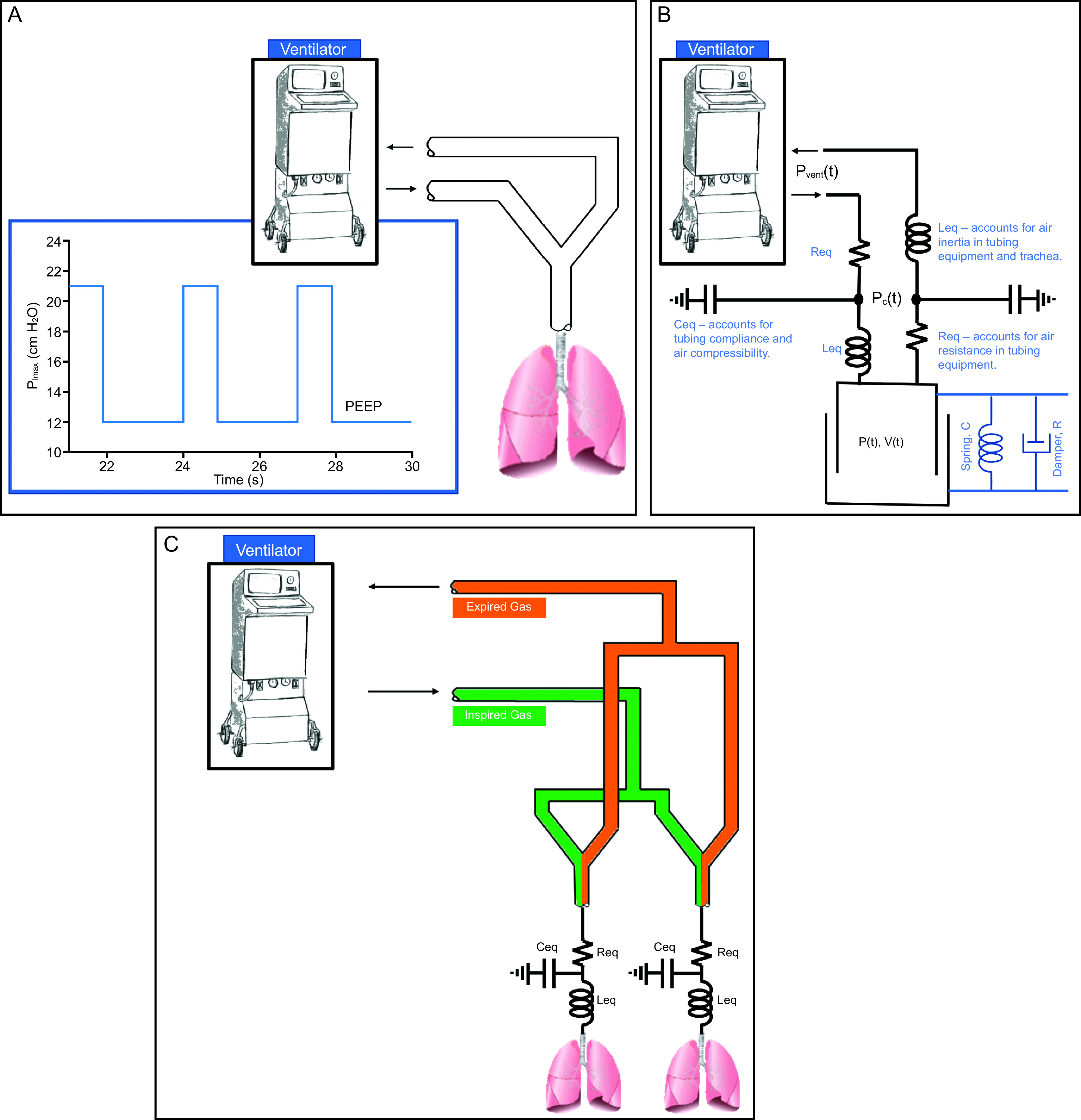
Schematic showing single-patient ventilation (A) with corresponding single-compartment model (B). Two patients on a shared single ventilator simulated using 2 single-compartment models (C).
The respiratory system is assumed to behave as a single linear compartment25 that is characterized by 2 parameters: compliance (mL/cm H2O) and resistance (cm H2O/L/s), which is the sum of tissue viscoelasticity and air flow resistance within the lungs and the endotracheal tube.25 Given these 2 characteristics of patient-specific lung mechanics, which can be measured at bedside, the pressure-volume relationship within the lungs is described by Equation (1),25 where P is the time-varying pressure at the entrance to the endotracheal tube (cm H2O) and V is the time-varying volume inside the lungs (L).
| [1] |
The time constant of this model (τ) = RC. When combining Equation (1) with a lumped-parameter model of the circuitry running from the ventilator to the patient, we derive the following governing equations:
| [2] |
| [3] |
In Equation (2) and Equation (3), Pvent is the pressure at the ventilator, and PC is the pressure in the ventilator circuit (Fig. 1). Leq is the ventilator circuit equipment gas inertance (0.02 cm H2O/L/s2, computed on the basis of Guttman et al26), which accounts for pressure changes in phase with air flow acceleration due to gas inertia. Req is the circuit equipment resistance (3.0 cm H2O/L/s, per manufacturer instructions), which represents aerodynamic drag losses encountered between the ventilator and the patient. Finally, Ceq is circuit equipment compliance, accounting for both tubing compliance and air compression (2.0 mL/cm H2O).27 The subscript “eq” in these 3 parameters indicates that they describe the properties of the equipment (eg, the ventilator circuit). Equation (2) and Equation (3) were solved using the adaptive Fehlberg method in Matlab (MathWorks, Natick, Massachusetts).
Model Validation
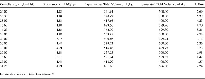
Computed VTs from the lumped-parameter model (described above) were validated against an experiment conducted by Branson et al.2 In that experiment, a ventilator was modified to allow attachment of 4 circuits, with each circuit being connected to a chamber of 2 dual-chambered test lungs. We tested 11 configurations of pressure-targeted ventilation under various combinations of resistance and compliance. It is important to note that Branson et al2 performed experiments under 16 configurations, but 3 were under identical conditions to identify the standard deviation of measurement noise. The final VT values reported were extracted from the manuscript using the WebPlotDigitizer.28 Figure 2 shows correlation and Bland-Altman plots comparing the resulting VT values between the aforementioned experiment and simulations executed under the same ventilation conditions (pressure control = 10 cm H2O, PEEP = 5 cm H2O, breathing frequency = 10 breaths/min, and inspiratory:expiratory ratio [I:E] = 1:1) (Table 1). The model predicted 96% of the variability in the experiments and consistently overestimates VT by a mean ± SD of −24.2 ± 23.12 mL.
Fig. 2.
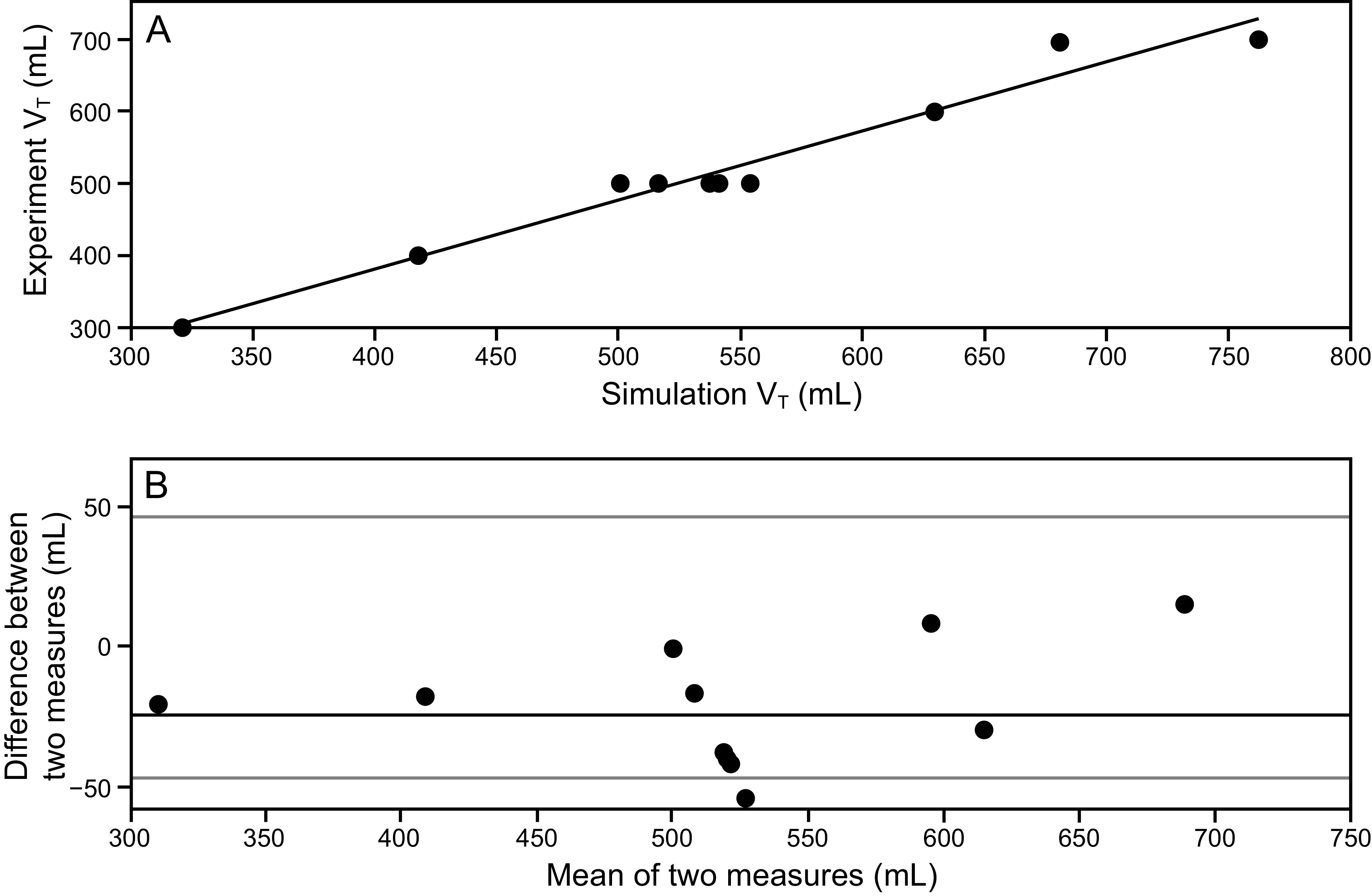
Comparison analysis between experiments reported by Branson et al2 and simulations results. A: Correlation analysis between measured and simulated tidal volume. B: Bland-Altman plot, with consistent bias (black line) and 1.96 SD (gray lines).
Table 1.
Simulation and Experimental Lung Compliance and Resistance Values Compared for Model Validation
Parametric Analysis
To evaluate VT sensitivity to patient-lung mechanics, the model was executed across a parameter space that included 1,600 combinations (ie, a 40 × 40 matrix) of 5 ≤ resistance ≤ 30 cm H2O/L/s and 20 ≤ compliance ≤ 80 mL/cm H2O. The computed VT and end-inspiratory volume across the entire considered parameter space was then used to generate contour plots. This range of parameters encompasses the values reported for patients with ARDS and COVID-1929 and patients with ARDS but not COVID-19.30
Results
Figure 3 shows simulation results for 4 simulated patients with differing lung compliance and resistance: Patient 1: compliance = 15 mL/cm H2O, resistance = 10 cm H2O/L/s; Patient 2: compliance = 60 mL/cm H2O, resistance = 10 cm H2O/L/s; Patient 3: compliance = 15 mL/cm H2O, resistance = 17 cm H2O/L/s; and Patient 4: compliance = 60 mL/cm H2O, resistance = 17 cm H2O/L/s. These simulations were carried out using a PEEP of 5 cm H2O, a pressure control level of 10 cm H2O above the set PEEP, an I:E of 1:2, and a breathing frequency of 20 breaths/min. Using this terminology, the inspiratory pressure delivered by the ventilator (relative to the atmosphere) is PEEP + pressure control. The tubing running from the ventilator to the patients was considered to have resistance (Req) of 3 cm H2O/L/s, gas inertance (Leq) of 0.02 cm H2O/L/s2, and a circuit compliance (Ceq) of 2 mL/cm H2O. The model accurately predicts expected trends in inspiratory/expiratory flow, VT, and ventilator pressures. As expected, increasing compliance causes an increase in VT and end-expiratory volume when holding ventilator pressure, resistance, and PEEP constant. Increased resistance causes delayed filling, which can also be estimated by the time constant, τ = RC. A time constant is the duration of time required to fill or empty 63% of the lungs31 after a step change in pressure. As is well known in clinical practice and is shown by these simulations, patients with a higher τ require longer expiratory time to avoid breath-stacking (auto-PEEP).32
Fig. 3.
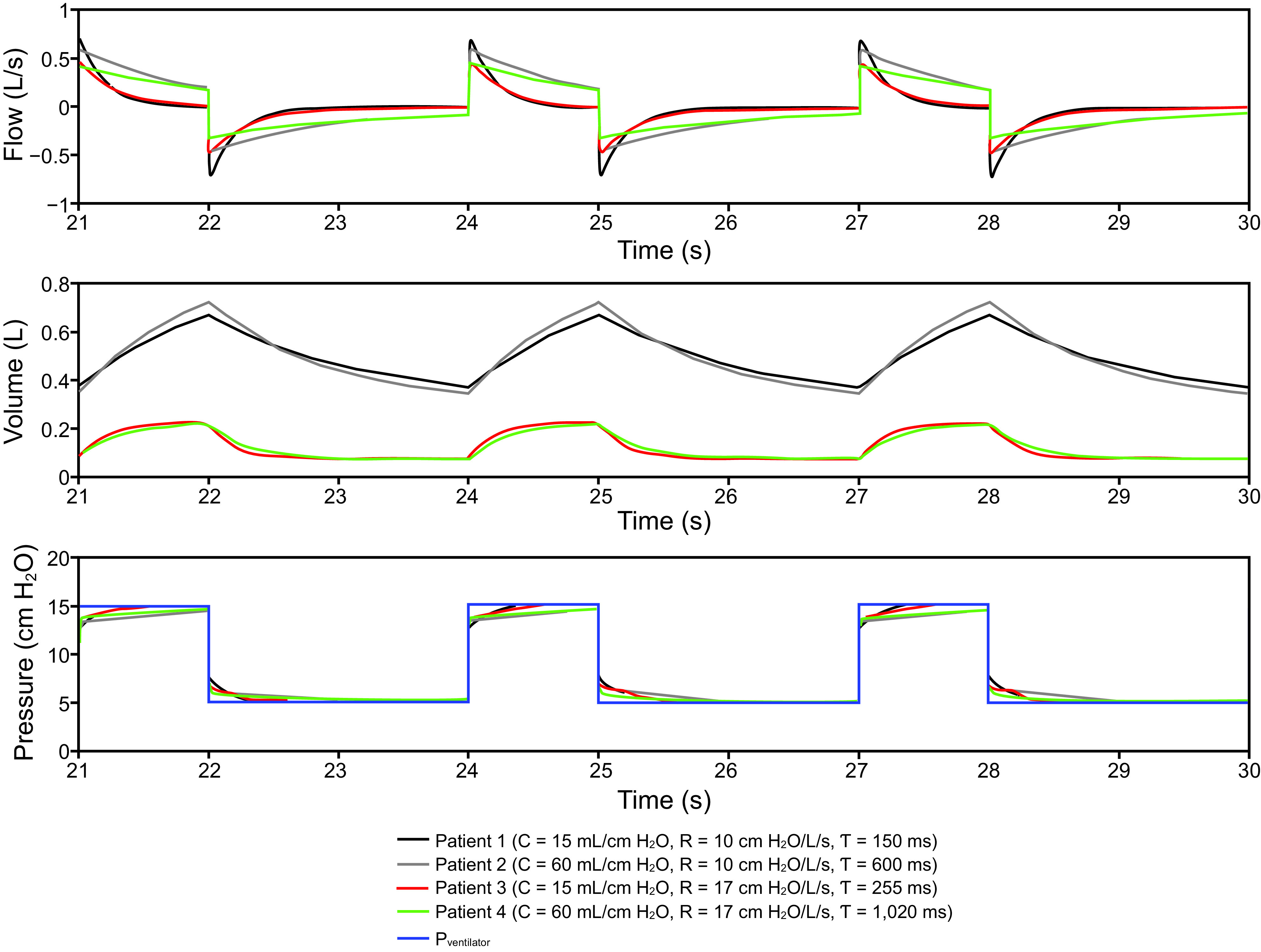
Four simulated patients at different values of lung resistance (R) and compliance (C). Each patient was simulated using pressure control = 10 cm H2O + PEEP 5 cm H2O, breathing frequency = 20 breaths/min, and an inspiratory:expiratory ratio = 1:2. Modeling results show that increased compliance causes increased end-inspiratory and end-expiratory volumes. Increased resistance delays filling, and an increased time constant (τ = RC) could result in auto-PEEP.
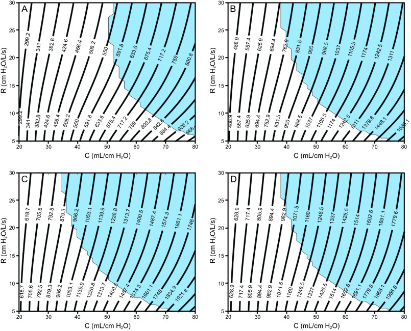
Figure 4 and Figure 5 show contour plots of VT and total end-inspiratory volume, respectively, for 4 ventilator groups: (1) pressure control of 15 cm H2O, PEEP of 5 cm H2O, breathing frequency = 10 breaths/min, I:E = 1:2; (2) pressure control of 14 cm H2O, PEEP of 10 cm H2O, breathing frequency = 20 breaths/min, I:E = 1:2; (3) pressure control of 16 cm H2O, PEEP of 14 cm H2O, breathing frequency = 20 breaths/min, I:E = 1:2; (4) pressure control of 14 cm H2O, PEEP of 16 cm H2O, breathing frequency = 20 breaths/min, I:E = 1:2.
Fig. 4.
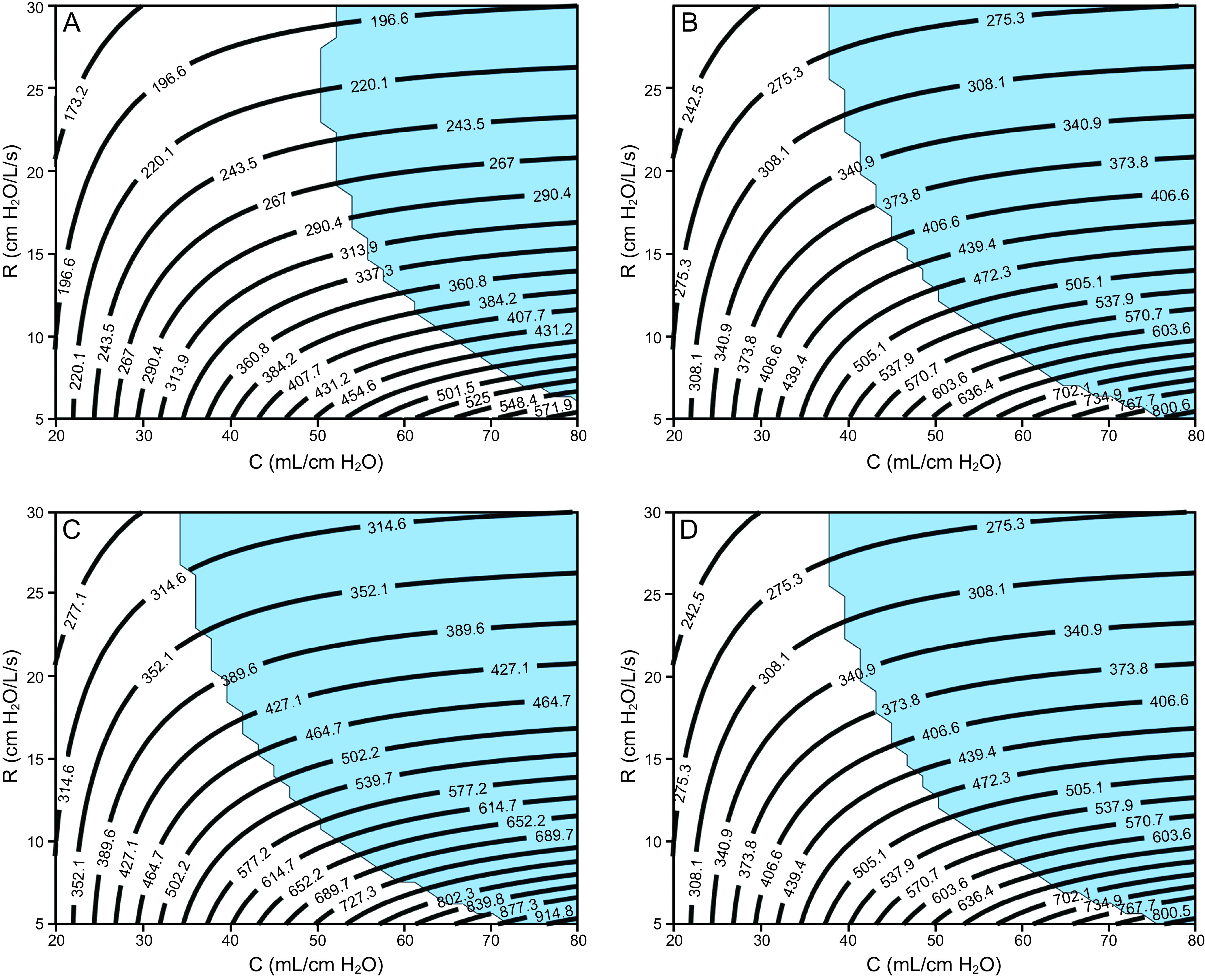
Contour plots showing ranges of estimated tidal volumes for various resistance (R) and compliance (C) values (patient-specific lung mechanics) evaluated for 4 ventilator settings with different PEEP and pressure control levels. In all cases, the breathing frequency is 20 breaths/min, and the inspiratory:expiratory ratio is 1:2. Light blue shading indicates that the end-expiratory flow was > 0.05 L/s, which indicates incomplete expiration (ie, auto-PEEP). A: PC of 15 cm H2O + 5 cm H2O of PEEP, B: PC of 14 cm H2O + 10 cm H2O of PEEP, C: PC of 16 cm H2O + 14 cm H2O of PEEP, and D: PC of 14 cm H2O + 16 cm H2O of PEEP.
Fig. 5.
Contour plots showing ranges of estimated end-inspiratory volume for various resistance (R) and compliance (C) values (patient-specific lung mechanics) evaluated for 4 ventilator settings with different PEEP and pressure control levels. In all cases, the breathing frequency is 20 breaths/min, and the inspiratory:expiratory ratio is 1:2. Light blue shading indicates that the absolute value of end-expiratory flow was > 0.05 L/s, which indicates incomplete expiration (ie, auto-PEEP). A: PC of 15 cm H2O + 5 cm H2O of PEEP, B: PC of 14 cm H2O + 10 cm H2O of PEEP, C: PC of 16 cm H2O + 14 cm H2O of PEEP, and D: PC of 14 cm H2O + 16 cm H2O of PEEP.
These 4 groups were chosen based on bedside observations of patients with ARDS and COVID-19 currently being treated at the University of Colorado Anschutz Medical Campus. Recall that the pressure control level is applied on top of the PEEP so that the inspiratory pressure applied by the ventilator (relative to atmospheric pressure) is PEEP + pressure control. Each plot also shows a region shaded light blue, which indicates a potential for auto-PEEP (where the absolute value of end-expiratory flow was > 0.05 L/s). In this scenario, failure to recognize auto-PEEP may lead to barotrauma, hemodynamic instability, and unnecessary vasopressor therapy. See the supplementary materials at http://www.rcjournal.com for additional simulation results for a breathing frequency of 12 breaths/min and I:E = 1:4.
Discussion
We created a computational model that relates pressure control ventilation settings (ie, pressure control, PEEP, breathing frequency, I:E) to patient-lung volume on the basis of patient-specific respiratory mechanics (resistance and compliance). The purpose of this study is to offer insights into ventilating 2 patients on a single ventilator in a setting where there are 4 groups of ventilators with pressure control settings that are based on the required level of support on the lower PEEP/ ARDSNet scale. However, we stress that the final settings for these ventilator groups will likely require adjustments as additional clinical data becomes available for patients with COVID-19, or this approach could be used for a more stable and better characterized patient cohort in order to free up ventilators for patients with COVID-19.
Lung Volume, Ventilator Settings, and Patient-Specific Lung Mechanics
The computational parametric study shows proof-of-concept contour plots that could be used to assign a patient to a preset ventilator group on the basis of that patient’s lung mechanics (resistance and compliance) and desired VT. Contour plots in Figure 4 and Figure 5 show that the VT at low τ (ie, low resistance and compliance) is more dependent on compliance but becomes more dependent on resistance as compliance increases (ie, as the contour plots become more horizontal). This is because high resistance reduces the large inspiratory flows necessary to deliver high VT to the compliant lung, and this effect is exacerbated for shorter inspiratory durations (see the supplementary materials at http://www.rcjournal.com). Increased resistance also increases the likelihood for auto-PEEP. The dependence of VT on resistance presents a pathway to patient-specific VT adjustments through the use of a variable flow resistor on the inspiratory circuit.8 In addition, ventilator groups 2 and 4, which both had the same pressure control setting but different PEEP, revealed almost identical VT values, but ventilator 4 had significantly increased end-inspiratory volume, which is almost entirely dependent on compliance.
Modeling and Implementation Considerations
This study is designed for pressure control ventilation, where the gas volume delivered to each patient is dictated by the pressure gradient between the ventilator and the lung. Therefore, assuming that the ventilator can provide adequate VT and flows to support all patients (this must be experimentally confirmed for each machine), the lung mechanics of a single patient should not impact gas delivery to other patients sharing that ventilator. This assumes an absence of respiratory drive achieved through deep sedation or neuromuscular blockade to prevent spontaneous breathing efforts. Consequently, considering a scenario where multiple groups of ventilators are preset with different pressure control configurations, the challenge is to assign an incoming patient to the correct group to maintain safe lung volumes.33,34 Although the contour plots presented in this manuscript could be used as a guide, the final patient VT would need to be confirmed at the bedside using a respiratory profile monitor (eg, NM3 monitor, Phillips Healthcare, Amsterdam, The Netherlands).
Under steady-state pressure control ventilation, the lung mechanics of one patient should not substantially affect gas delivery to other patients on that shared ventilator. However, several exceptions must be considered. First, acute changes in 1 patient (eg, pneumothorax, kinked endotracheal tube, rapid change in lung function) could interfere with flow distributions to the other patients until the ventilator regulates itself back to the set pressure control configuration. This response should be investigated for different clinical ventilators in future experimental studies. Furthermore, the shape of the delivered pressure waveform could change with the total impedance of the combined patients because no ventilator is a perfect pressure controller.
Second, although inertia is included in the current model, the value for Leq is low enough that it does not significantly contribute to air flow dynamics during ventilation. However, our model does reveal that if Leq is large enough (ie, > 2 cm H2O/L/s2, which can be seen in higher ventilation frequencies and smaller tracheal tubes35), there could be a scenario where the tracheal pressure is lower than PEEP in a single patient during expiration. Therefore, the expired air from 1 patient, flowing through the expiratory tubing back to the ventilator, could theoretically be drawn into another patient by inertial effects. Again, the model would suggest that this possibility exists in cases of high-flow inertia, which is not likely to occur in adults.
Third, it is critical that the sum of VT to all 4 patients does not exceed the tidal capacity of the ventilator. For example, the experiment performed by Smith and Brown7 with only 2 patients would have exceeded the 2-L tidal capacity of the Hamilton-G5 SW 2.8x ventilator.
Limitations
The serious clinical limitations of utilizing a single ventilator for multiple patients has been extensively outlined in previous clinical and experimental studies.1,2,5,6 Our study had several limitations of its own. Figure 4 and Figure 5 are derived from a purely mathematical model, which has only been validated against a single experimental study that was performed using a single type of ventilator and artificial lungs.2 Therefore, additional validation experiments will need to be performed in in vitro, animal, and clinical studies.
Also, we used a single-compartment model to represent the acutely injured lung. This simplification was done to allow comparison of results to the limited measurements of lung function that are available from clinical ventilators. Although this representation describes the important features of lung mechanics, namely the elastic and resistive properties, it does not account for volume-dependent stiffening at high lung volumes. It also does not account for the time- and pressure-dependence of alveolar de-recruitment.36 Although these factors are not explicitly simulated, they are represented in lung compliance.
Conclusions
The computational modeling approach presented in this study could serve for rapidly evolving research on the feasibility of sharing 1 ventilator between > 1 patient. In vitro and in vivo experiments suggest that this may not be impossible, but great care must be taken to avoid ventilator-induced lung injury and other potentially catastrophic complications. We present a hypothetical graphical guide for a scenario in which 4 ventilators are set at different pressure control, PEEP, breathing frequency, I:E ratio, and the resulting delivered VT based on patient-specific resistance and compliance. Although we believe our findings may be helpful to develop a better understanding of the limitations of the shared ventilator concept, we strongly caution against applying them to patient care at this time.
Footnotes
This work was supported in part by the National Institutes of Health (NIH K25 HL133481, NIH R00HL128944). The authors have disclosed no conflicts of interest.
Supplementary material related to this paper is available at http://www.rcjournal.com.
References
- 1.American Association for Respiratory Care. Joint statement on multiple patients per ventilator. Available at: https://www.aarc.org/wp-content/uploads/2020/03/032620-covid-19-press-release.pdf?sfns=mo Accessed May 8, 2020.
- 2.Branson RD, Blakeman TC, Robinson BR, Johannigman JA. Use of a single ventilator to support 4 patients: laboratory evaluation of a limited concept. Respir Care 2012;57(3):399-403. [DOI] [PubMed] [Google Scholar]
- 3.Paladino L, Silverberg M, Charchaflieh JG, Eason JK, Wright BJ, Palamidessi N, et al. Increasing ventilator surge capacity in disasters: ventilation of four adult-human-sized sheep on a single ventilator with a modified circuit. Resuscitation 2008;77(1):121-126. [DOI] [PubMed] [Google Scholar]
- 4.Neyman G, Irvin CB. A single ventilator for multiple simulated patients to meet disaster surge. Acad Emerg Med 2006;13(11):1246-1249. [DOI] [PMC free article] [PubMed] [Google Scholar]
- 5.Branson RD, Rubinson L. One ventilator multiple patients: what the data really supports. Resuscitation 2008;79(1):171-172. [DOI] [PubMed] [Google Scholar]
- 6.Branson RD, Rubinson L. A single ventilator for multiple simulated patients to meet disaster surge. Acad Emerg Med 2006;13(12):1352-1353. [DOI] [PubMed] [Google Scholar]
- 7.Smith R, Brown JM. Simultaneous ventilation of two healthy subjects with a single ventilator. Resuscitation 2009;80(9):1087. [DOI] [PMC free article] [PubMed] [Google Scholar]
- 8.Herrmann J, Fonseca da Cruz A, Hawley ML, Branson RD, Kaczka DW. Shared ventilation in the era of COVID-19: a theoretical consideration of the dangers and potential solutions. Respir Care 2020. [Epub ahead of print] [DOI] [PubMed] [Google Scholar]
- 9.Slutsky AS, Ranieri VM. Ventilator-induced lung injury. N Engl J Med 2013;369(22):2126-2136. [DOI] [PubMed] [Google Scholar]
- 10.Webb HH, Tierney DF. Experimental pulmonary-edema due to intermittent positive pressure ventilation with high inflation pressures: protection by positive end-expiratory pressure. Am Rev Respir Dis 1974;110(5):556-565. [DOI] [PubMed] [Google Scholar]
- 11.Kolobow T, Moretti MP, Fumagalli R, Mascheroni D, Prato P, Chen V, et al. Severe impairment in lung function induced by high peak airway pressure during mechanical ventilation: an experimental study. Am Rev Respir Dis 1987;135(2):312-315. [DOI] [PubMed] [Google Scholar]
- 12.Dreyfuss D, Soler P, Basset G, Saumon G. High inflation pressure pulmonary edema. Respective effects of high airway pressure, high tidal volume, and positive end-expiratory pressure. Am Rev Respir Dis 1988;137(5):1159-1164. [DOI] [PubMed] [Google Scholar]
- 13.Hernandez LA, Peevy KJ, Moise AA, Parker JC. Chest wall restriction limits high airway pressure-induced lung injury in young rabbits. J Appl Physiol 1989;66(5):2364-2368. [DOI] [PubMed] [Google Scholar]
- 14.Carlton DP, Cummings JJ, Scheerer RG, Poulain FR, Bland RD. Lung overexpansion increases pulmonary microvascular protein permeability in young lambs. J Appl Physiol 1990;69(2):577-583. [DOI] [PubMed] [Google Scholar]
- 15.Seah AS, Grant KA, Aliyeva M, Allen GB, Bates J. Quantifying the roles of tidal volume and PEEP in the pathogenesis of ventilator-induced lung injury. Ann Biomed Eng 2011;39(5):1505-1516. [DOI] [PubMed] [Google Scholar]
- 16.Smith BJ, Bates J. Assessing the progression of ventilator-induced lung injury in mice. IEEE Trans Biomed Eng 2013;60(12):3449-3457. [DOI] [PMC free article] [PubMed] [Google Scholar]
- 17.Smith BJ, Grant KA, Bates JH. Linking the development of ventilator-induced lung injury to mechanical function in the lung. Ann Biomed Eng 2013;41(3):527-536. [DOI] [PMC free article] [PubMed] [Google Scholar]
- 18.Muscedere JG, Mullen JBM, Gan K, Slutsky AS. Tidal ventilation at low airway pressures can augment lung injury. Am J Respir Crit Care Med 1994;149(5):1327-1334. [DOI] [PubMed] [Google Scholar]
- 19.Slutsky AS. Lung injury caused by mechanical ventilation. Chest 1999;116(Suppl 1):9S-15S. [DOI] [PubMed] [Google Scholar]
- 20.dos Santos CC, Slutsky AS. The contribution of biophysical lung injury to the development of biotrauma. Annu Rev Physiol 2006;68:585-618. [DOI] [PubMed] [Google Scholar]
- 21.Tremblay LN, Slutsky AS. Ventilator-induced injury: from barotrauma to biotrauma. P Assoc Am Physician 1998;110(6):482-488. [PubMed] [Google Scholar]
- 22.Halbertsma FJJ, Vaneker M, Scheffer GJ, van der Hoeven JG. Cytokines and biotrauma in ventilator-induced lung injury: a critical review of the literature. Neth J Med 2005;63(10):382-392. [PubMed] [Google Scholar]
- 23.Uhlig S, Ranieri M, Slutsky AS. Biotrauma hypothesis of ventilator-induced lung injury. Am J Respir Crit Care Med 2004;169(2):314-315. [DOI] [PubMed] [Google Scholar]
- 24.Marini JJ. Dissipation of energy during the respiratory cycle: conditional importance of ergotrauma to structural lung damage. Curr Opin Crit Care 2018;24(1):16-22. [DOI] [PubMed] [Google Scholar]
- 25.Bates J. Lung mechanics: an inverse modeling approach. Cambridge, UK: Cambridge University Press, 2009. [Google Scholar]
- 26.Guttmann J, Kessler V, Mols G, Hentschel R, Haberthur C, Geiger K. Continuous calculation of intratracheal pressure in the presence of pediatric endotracheal tubes. Crit Care Med 2000;28(4):1018-1026. [DOI] [PubMed] [Google Scholar]
- 27.Maria G, Masselli P, Silvestri S, Sciuto SA, Cappa P. Circuit compliance compensation in lung protective ventilation, 2006 International Conference of the IEEE Engineering in Medicine and Biology Society, 2006. [DOI] [PubMed] [Google Scholar]
- 28.Rohatgi A. WebPlotDigitizer: HTML5 based online tool to extract numerical data from plot images. Available at: https://automeris.io/WebPlotDigitizer/tutorial.html Accessed June 23, 2020.
- 29.Gattinoni L, Coppola S, Cressoni M, Busana M, Rossi S, Chiumello D. COVID-19 does not lead to a “typical” acute respiratory distress syndrome. Am J Resp Crit Care 2020;201(10):1299-1300. [DOI] [PMC free article] [PubMed] [Google Scholar]
- 30.Henderson WR, Chen L, Amato MBP, Brochard LJ. Fifty years of research in ARDS. Respiratory mechanics in acute respiratory distress syndrome. Am J Respir Crit Care Med 2017;196(7):822-833. [DOI] [PubMed] [Google Scholar]
- 31.Hess DR. Respiratory mechanics in mechanically ventilated patients. Respir Care 2014;59(11):1773-1794. [DOI] [PubMed] [Google Scholar]
- 32.Lain DC, Chaudhary BA, Thorarinsson B, Speir WA., Jr. Auto-PEEP and proximal airway pressure. Need for clarification. Chest 1990;97(4):771. [DOI] [PubMed] [Google Scholar]
- 33.ARDSNetwork, Brower RG, Matthay MA, Morris A, Schoenfeld D, Thompson BT, Wheeler A. Ventilation with lower tidal volumes as compared with traditional tidal volumes for acute lung injury and the acute respiratory distress syndrome. New Engl J Med 2000;342(18):1301-1308. [DOI] [PubMed] [Google Scholar]
- 34.Liu X, Liu X, Xu Y, Xu Z, Huang Y, Chen S, et al. Ventilatory ratio in hypercapnic mechanically ventilated patients with COVID-19–associated acute respiratory distress syndrome. Am J Respir Crit Care Med 2020;201(10):1297-1299. [DOI] [PMC free article] [PubMed] [Google Scholar]
- 35.Lanteri CJ, Petak F, Gurrin L, Sly PD. Influence of inertance on respiratory mechanics measurements in mechanically ventilated puppies. Pediatr Pulmonol 1999;28(2):130-138. [DOI] [PubMed] [Google Scholar]
- 36.Bobhate P, Guo L, Jain S, Haugen R, Coe JY, Cave D, et al. Cardiac catheterization in children with pulmonary hypertensive vascular disease. Pediatr Cardiol 2015;36(4):873-879. [DOI] [PubMed] [Google Scholar]


