Abstract
In the last two decades, sutureless (Perceval, Livanova PLC, London, UK) and rapid deployment (INTUITY Elite, Edwards Lifesciences, Irvine, CA, USA) valves were introduced to the market as an innovative alternative to traditional valves for patients needing aortic valve replacement (AVR). These devices have been used and studied extensively across these fifteen years, and have proven to be a valid alternative treatment option compared to sutured biological valves, particularly helpful in minimally invasive cardiac surgery, and an almost curative treatment to patients with intermediate to high surgical risk, filling the gap between transcatheter and traditional AVR. However, both sutureless and rapid deployment valves require special steps for implantation, and also a learning curve. Proper specific training to all surgical team members is required as mandatory by the manufacturers. The aim of this review article is to provide cardiac surgeons with a thorough guide on the implantation technique from A to Z, for each of these two prosthetic devices. In this second part of our review article, we will focus on the INTUITY Elite valve.
Keywords: Edwards, rapid deployment, INTUITY Elite, implantation technique
Introduction
Due to the drive toward transcatheter aortic valve replacement (TAVR), cardiac surgeons are continuously challenged to collect data and evidence to prove outcomes and benefits of aortic valve surgery. Minimizing invasiveness through new techniques and technologies has been the key goal in this scenario. Like the Perceval Sutureless Valve, described in the first part of our review article, the Edwards INTUITY Elite Rapid Deployment valve has also been devised to facilitate an easy, reproducible and safe implantation in a rapid fashion, reducing operating time and surgical complications (1-3). Like the Perceval sutureless valve, the INTUITY Elite also has specific indications and recommendations to follow (4). Therefore, we shall now move on to the implantation technique.
INTUITY Elite valve
The INTUITY Elite valve is a stented bovine pericardium valve, built on the Carpentier-Edwards PERIMOUNT valve platform. An expandable stainless steel cloth-covered frame is incorporated into the inflow side of the valve and is implanted with the aid of a delivery system. As in conventional AVR, the patient is placed on cardiopulmonary bypass and the native leaflets are excised during the procedure. The system may be used in both conventional and less invasive surgical procedures.
The INTUITY Elite valve is designed to be compatible with your current surgical AVR technique, with standard access to the aorta and preferred cannulation.
Aortotomy
The Edwards INTUITY Elite Valve requires an aortotomy that usually crosses the sinotubular junction (STJ) down in the noncoronary (NC) sinus. This enables good access to the annulus with easy excision of the valve and appropriate (defensive) decalcification of the annulus. As the fixation of the valve is in the sub-annular region, the aortic wall around the aortotomy remains flexible enough to facilitate easy closure.
Caution
If a transverse aortotomy is used and the STJ diameter is estimated to be equal or smaller than the annulus diameter, it is recommended to extend aortotomy into the NC sinus, to facilitate sizer and implant insertion. If an extension of the aortotomy is not possible, it is not recommended to use this valve, as parachuting through a narrow STJ may increase the difficulty of implantation and/or cause aortic injury.
Leaflet excision and debridement
Debridement should be performed as per standard practice in any conventional surgical AVR. Debridement of calcium from the native annulus, left ventricular outflow tract (LVOT) and the anterior mitral valve leaflet is essential to ensure proper seating of the valve on the annulus and for optimal frame expansion. Avoid excessive or eccentric debridement that may result in annular injury, compromise the integrity of the aortic annulus and/or result in a paravalvular leak (PVL).
A severely calcified LVOT that is not properly debrided may result in balloon rupture during inflation. The final decision to use the INTUITY Elite valve should only be made after native valve removal and annulus decalcification. An assessment of the potential interaction between the prosthesis and the surrounding structures (the aortic annulus, anterior leaflet of the mitral valve and coronary ostia) should be conducted to ensure appropriate use of the device. Failure to consider these factors may lead to implant failure and clinical complications including, but not limited to, interference with mitral valve function and severe conduction disturbances requiring permanent pacemaker implantation.
Sizing
Selection of the appropriate valve size is a critical step in the implantation of the INTUITY Elite valve. As the valve features a supra-, intra- and sub-annular aspects, size selection should take into account each of the following aspects:
❖ What impact the valve profile will have on the aortic wall and the ostia;
❖ How the valve will sit on the annulus;
❖ How the inflow frame will expand sub-annularly.
Using only a supra-annular sizing technique is not recommended with the INTUITY Elite. Both supra and sub-annular sizing techniques should be used.
Magna Ease sizers are used to define the right valve diameter and a sizer is available for each valve diameter. Select a sizer that you feel best matches the size of the native annulus, insert the sizer barrel end through the aortotomy and place it into the aortic root and annulus. Ideal fit for the barrel is noted when there is complete apposition of the barrel with the native annular tissue. No force has to be applied to pass through the annulus.
The largest sizer that will comfortably fit within the annulus is the correct one. If the annulus measurement is between two valve sizes, selection of the smaller size valve is recommended. The tip of the barrel represents the sewing cuff of the valve therefore it is intended to sit on the annulus and not to pass through it. For good practice, to confirm the correct size, it is recommended to test the two contiguous sizers, smaller and larger (Figure 1).
Figure 1.
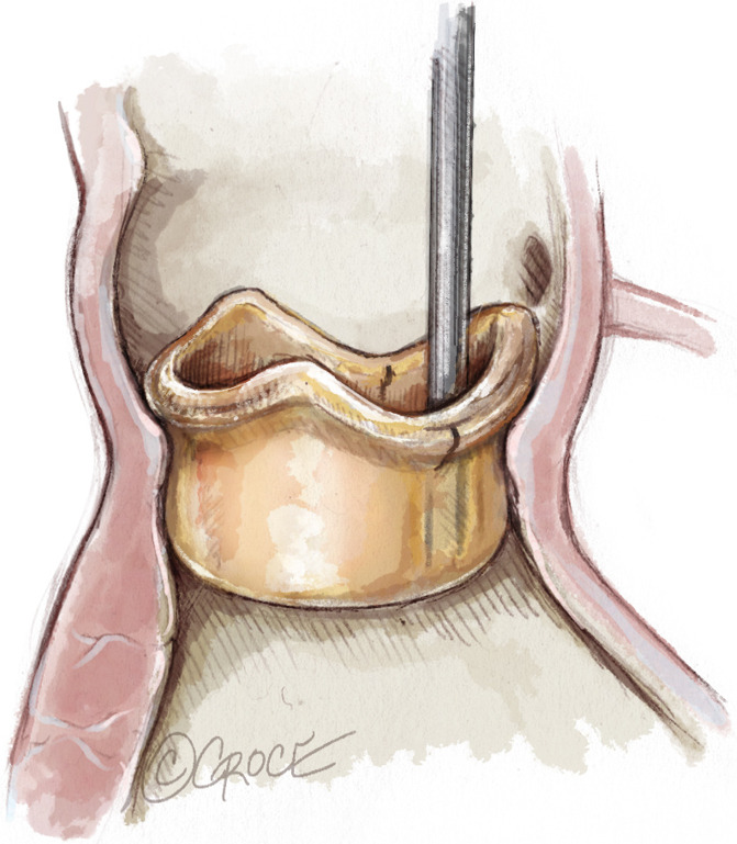
INTUITY Elite valve sizing.
Warning
Do not select a valve size based on the sizer that will fit through the STJ, as it may result in PVL, due to the use of an undersized valve.
Replica sizers simulate the supra-annular relative position of the valve with respect to the native commissures, to establish the baseline for final allocation.
The black orientation markers on the replica end of the sizer can be used to identify relative locations of anatomic landmarks, such as the mid-commissural points and the coronary ostia. Additionally, they are used to determine ideal seating location of the valve on the annulus and assess guiding suture placement in the annulus (Figure 2).
Figure 2.
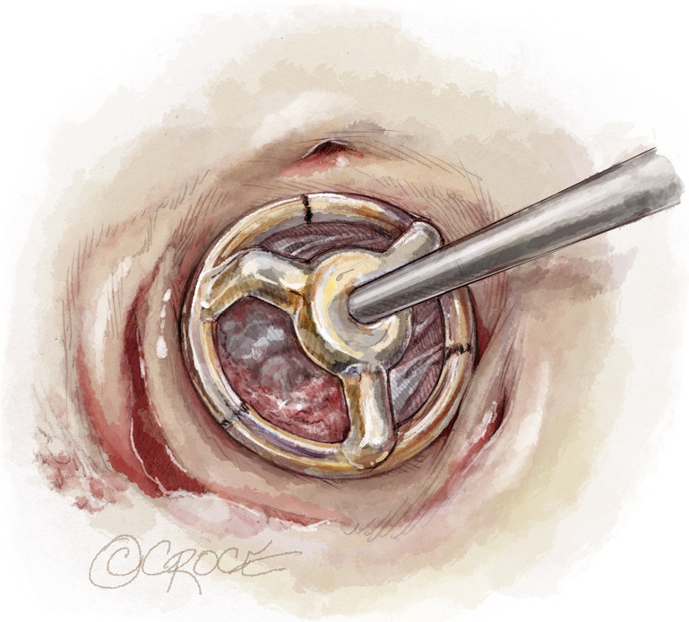
Replica sizers simulate the ideal supra-annular position of the valve with respect to the native commissures.
Suture placement
Once the valve size has been determined, the balloon catheter and inflation device can be prepared, while three equally spaced sutures are being placed through the aortic annulus to fixate the valve, preferably at the nadir of each cusp (Figure 3).
Figure 3.
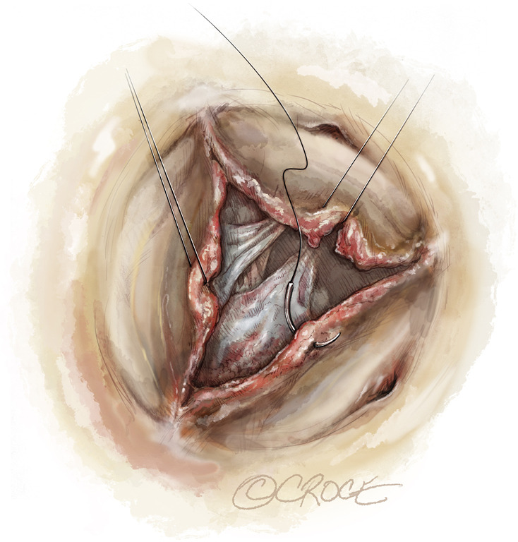
Guiding sutures placement through the annulus.
Conventional suturing techniques can be used with this valve. On surgeon preference, single, “U” or “figure eight” stiches can be applied. The three guiding sutures are used to align the valve onto the aortic annulus and guide valve orientation.
Pledgeted sutures are not recommended. Use non-pledgeted, braided, polyester coated sutures with non-cutting needles to place the three guiding sutures in the mid-commissural or nadir region of the annulus. The use of pledgets may create channels resulting in PVL’s. The use of monofilament sutures and resulting suture tails may damage the leaflets.
Be sure there are no loops or gaps in the suture when using the figure of eight technique in calcified areas of the annulus. It is easier to slide the suture tight against the annulus when using the non-everting technique in calcified areas of the annulus.
Maintain an equal distance between the sutures at approximately 120 degrees apart. Suture the needle bite completely through the annulus and ensure adequate needle bites are taken into the annulus to prevent suture pullout.
Once the guiding sutures are secured in the aortic annulus, place the three guiding sutures through the sewing ring in positions corresponding to the annular suture positions.
The balloon catheter size is specific to the size of the valve. Ensure you check that the balloon size matches the valve size before using it. The balloon size in mm is printed on the hub of the balloon catheter. Interchange of balloon catheters between delivery systems may result in improper inflow frame expansion.
The delivery system is used to hold the valve while the guiding sutures are placed through the sewing ring.
Valve placement or parachuting
Once the guiding sutures are placed in the sewing ring, the INTUITY Elite valve can be parachuted onto the native annulus, using the delivery system and maintaining counter traction on the sutures.
During parachuting, it is important to maintain simultaneous even tension on the three guiding sutures in the vertical or parallel direction. This will also help to prevent entanglement of the guiding sutures with the valve inflow frame (Figure 4A,B).
Figure 4.
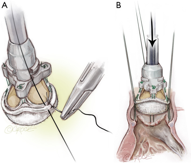
Valve placement. (A) Guiding sutures are placed in the sewing ring; (B) INTUITY Elite valve parachuted onto the native annulus with delivery system.
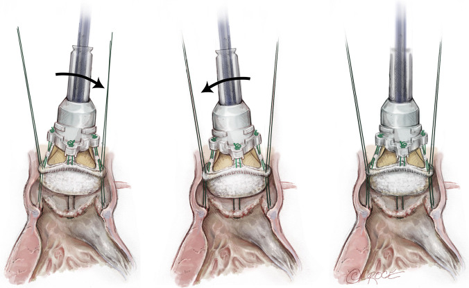
Use the delivery system to guide the Edwards INTUITY Elite valve to the level of the native annulus. It is important to assess that the sewing ring is located on the annulus at the point of the three mid-commissural or nadir guiding sutures.
Adjust valve placement on the annulus by using the delivery system and gently tilt the valve right, left, front and back to ensure ideal seating. When properly seated, the valve should not appear tilted or canted on the annulus. Using the delivery system, ensure the valve is maintained in position throughout all the seating and expansion procedure (Figure 5).
Figure 5.
Valve tilting on the annulus to ensure ideal seating.
Malleable handle
The malleable handle is used to facilitate valve placement.
Warning
Bending the malleable handle too sharply will affect frame expansion; any bending exceeding 90 degrees should be considered excessive!
Caution
Avoid bending the malleable handle more than three times and beyond 90°.
Use of snares
Once the valve is properly seated on the annulus, the use of snares or tourniquets helps to secure the position of the valve prior to and during balloon expansion of the frame. To apply the snares/tourniquets, confirm that the position of the valve on the native annulus is ideal and does not require adjustments.
Next, thread the guiding suture through the snare using a snare hook and slide the snare to the level of the sewing ring. While applying constant tension to the guiding suture, place a hemostat on the distal end of the snare (Figure 6).
Figure 6.
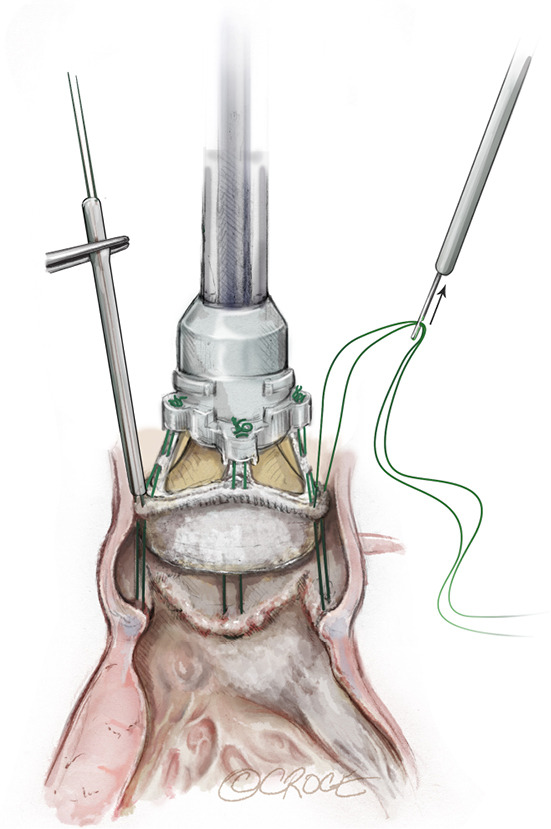
Use snares or tourniquets to secure the position of the valve prior to and during balloon expansion.
Note
Placement of the hemostat should be accomplished while applying tension to the guiding suture and ensuring the snare is tight against the sewing ring. Ensure the snare is placed directly on the sewing ring and not on the valve holder legs as this may result in loose sutures or difficulty in removing the holder/delivery system once the holder sutures are cut. Repeat the snare placement procedure for the remaining guiding sutures.
Placement of the balloon catheter
After the device is secured in the patient annulus with snares, advance the balloon catheter distally until the catheter snaps into place and an audible “click” is heard. Be sure to stabilize the handle while advancing the balloon catheter.
The inflow frame of the valve is expanded in a precise manner based upon the position of the balloon catheter within the delivery system and specific inflation pressures. The position of the balloon catheter is controlled through the use of a locking mechanism on the delivery system (Figure 7).
Figure 7.
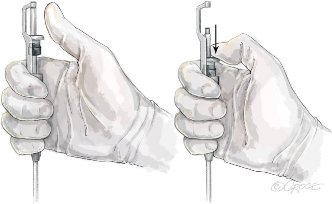
Placement of the balloon catheter.
Balloon inflation and inflow frame expansion
The inflow frame expansion process for the Edwards INTUITY Elite valve is unique and different from any other inflation devices and balloon inflation techniques; it is a pressure-based balloon inflation method, not volume based.
Inflation of the balloon catheter is accomplished using the inflation device that is packaged with the delivery system and following these recommended steps:
Unlock the inflation device by pushing the lock lever to the left.
Place the connecting tubing into saline solution and fill the inflation device with sterile physiological saline to a final volume of 25 cc by withdrawing the plunger.
Remove any large amounts of air.
Lock the inflation device by pushing the lock lever to the right.
Attach the inflation device to the Luer inflation port on the balloon catheter.
Prior to inflating the balloon, ensure that the valve position has not shifted or altered as a result of manipulation of the delivery system during insertion of the balloon catheter.
Stabilize the valve during expansion: this requires two people! Hold the delivery system perpendicular to the plane of the valve and apply gentle pressure in a distal direction to maintain proper seating of the valve during balloon inflation.
Frame expansion is a controlled process. Using the prepared inflation device, inflate the balloon to the correct balloon inflation pressure for the valve size using the following steps:
Unlock the lock lever by pushing it to the left.
Advance the plunger until resistance is felt.
Lock the lock lever by pushing it to the right.
Turn the knob for fine adjustment until the recommended nominal pressures are achieved.
Maintain the specified inflation pressure for 10 seconds, to ensure proper frame expansion.
It is very important to maintain the inflation pressure reported in the Inflation Pressures Table, by keeping an active hold on the knob for 10 seconds (Table 1).
Table 1. Table of Inflation Pressures per valve size.
| Valve size | Nominal inflation pressure (atm) |
|---|---|
| 19 mm | 4.5 |
| 21 mm | 4.5 |
| 23 mm | 4.5 |
| 25 mm | 5.0 |
| 27 mm | 5.0 |
Do not re-inflate the balloon. The balloon is designed for single use. Do not under inflate or over inflate the balloon. Under inflation may cause insufficient expansion of the frame and may result in PVL, thrombosis and/or thromboembolism. Over inflation may cause excessive frame expansion and may result in annular damage, conduction interference/arrhythmia or sub-annular tissue damage. Inflate the balloon only to the correct balloon inflation pressure for the valve size.
From a procedural perspective, it is recommended to stabilize the valve position during the inflow frame expansion process. This is typically achieved with one individual stabilizing the valve position while another individual inflates the balloon. The fixed position of the balloon catheter and the specific target inflation pressures allow balloon expansion of the inflow frame in a precise manner so that mechanical stress is not imparted upon the valve through leaflet contact. The balloon is specifically designed so it does not touch the leaflets.
If inflation pressure is not achieved, completely deflate the balloon by fully retracting the syringe plunger. Remove the valve and delivery system beginning with the removal of the snares and sutures. Do not retract the balloon catheter through the valve holder when removing the whole system. Use a new valve and delivery system, to avoid possible valve displacement.
Balloon deflation
Once the frame has reached optimal expansion, the balloon is deflated using the inflation device. Deflation of the balloon is achieved by unlocking the inflation device (pushing to the left), fully retracting the plunger to remove the saline from the balloon and locking the plunger in retracted position (pushing to the right).
Delivery system removal
After balloon deflation, the delivery system can be removed from the valve. Firstly detach the three retaining sutures of the valve holder by using a scalpel to cut each of the sutures. Once the retaining sutures have been cut, seat the valve with forceps. The delivery system, balloon catheter, and valve holder are then removed together, as one unit, by pulling the assembly upwards away from the valve. Confirm the holder retaining sutures are removed with the holder from the valve.
Once valve position has been confirmed, the snares can be removed, and the guiding sutures can be tied down. Remove the first snare and tie the corresponding guiding suture. Repeat these two steps for each of the remaining snares and guiding sutures.
Note: the guiding sutures are tied after balloon deflation to avoid placing pressure on them during inflow frame expansion.
After tying down the guiding sutures, inspect the valve before closing the aortotomy. Do not pass catheters or transvenous pacing leads across the valve as this may cause tissue damage.
Valve inspection
A careful inspection must be carried out before aortotomy closure. A hook may be used in case of suspicion of imperfect healing to verify the presence of PVL. Additional stitches can be added in this phase if required.
The frame must be checked to ensure it fits correctly in the distal LVOT.
Intraoperative removal and explant techniques
Residual PVL or dislodgment may require an intraoperative removal of the valve and delivery system after full or partial frame expansion. Valve removal is achieved as follows:
Completely deflate the balloon by fully retracting the syringe plunger and sliding the lever into the locked position.
Disconnect the inflation device from the delivery system.
Using a scalpel, cut each of the valve holder sutures.
Remove the delivery system and valve holder as a unit.
Remove the three snares and guiding sutures.
Using a blunt surgical tool between the valve and annulus, slightly bend the inflow frame inward on one side to facilitate valve removal. If the valve and annulus apposition is too tight, a tool such as a 180-degree nerve hook may be inserted through the leaflets to engage the edge of the inflow frame to bend it inwards.
Using forceps, grasp a stent post of the valve and carefully lift the valve upward from the annulus.
Valve explant is achieved as follows:
Detach each of the three guiding sutures found in the mid-commissural area on the sewing ring of the valve.
Perform a blunt dissection around the periphery of the valve to separate the frame from the surrounding tissue. As the tissue is separated from the frame, use the blunt surgical tool to slightly bend the frame inwards to facilitate valve removal.
Using forceps, grasp a stent post of the valve and carefully lift the valve upward from the annulus.
Acknowledgments
None.
Open Access Statement: This is an Open Access article distributed in accordance with the Creative Commons Attribution-NonCommercial-NoDerivs 4.0 International License (CC BY-NC-ND 4.0), which permits the non-commercial replication and distribution of the article with the strict proviso that no changes or edits are made and the original work is properly cited (including links to both the formal publication through the relevant DOI and the license). See: https://creativecommons.org/licenses/by-nc-nd/4.0/.
Footnotes
Conflicts of Interest: The authors have no conflicts of interest to declare.
References
- 1.Glauber M, Miceli A, di Bacco L. Sutureless and rapid deployment valves: implantation technique from A to Z-the Perceval valve. Ann Cardiothorac Surg 2020;9:330-40. 10.21037/acs-2020-surd-23 [DOI] [PMC free article] [PubMed] [Google Scholar]
- 2.Glauber M, Miceli A. Minimally invasive aortic valve replacement with sutureless valve is the appropriate treatment option for high-risk patients and the "real alternative" to transcatheter aortic valve implantation. J Thorac Cardiovasc Surg 2016;151:610-3. 10.1016/j.jtcvs.2015.10.028 [DOI] [PubMed] [Google Scholar]
- 3.Glauber M, Lio A, Miceli A. The gray zone is always more dark. J Thorac Cardiovasc Surg 2016;152:110-1. 10.1016/j.jtcvs.2016.03.012 [DOI] [PubMed] [Google Scholar]
- 4.Edwards Lifesciences LLC, Irvine, CA (USA): “EDWARDS INTUITY Elite Valve System Aortic Valve - Instructions for Use”.


