Abstract
Osteoid osteoma is a painful benign bone tumour of children and young adults with characteristic clinico-radiological features depending upon the location of the lesion. Intraoperative visualisation of the nidus is difficult and therefore curative surgery is often associated with excessive bone removal, significant perioperative morbidity and potential need of bone grafting procedures. With advancement in cross-sectional imaging and radiofrequency ablation (RFA) technology, CT-guided RFA has emerged as the treatment of choice for the osteoid osteoma. This procedure involves accurate cannulation of the nidus and subsequent thermocoagulation-induced necrosis.
Multidisciplinary management approach is the standard of care for patients with osteoid osteoma. Appropriate patient selection, identification of imaging pitfalls, pre-anaesthetic evaluation and a protocol-based interventional approach are the cornerstone for a favourable outcome. Comprehensive patient preparation with proper patient position and insulation is important to prevent complications. Use of spinal needle-guided placement of introducer needle, namely, “rail–road technique” is associated with fewer needle trajectory modifications, reduced radiation dose and patient morbidity and less intervention time. Certain other procedural modifications are employed in special situations, for example, intra-articular osteoid osteoma and osteoid osteoma of the subcutaneous bone in order to reduce complications. Treatment follow-up generally includes radiographic assessment and evaluation of pain score. Dynamic contrast-enhanced MRI has been recently found useful for demonstrating post-RFA healing.
Introduction
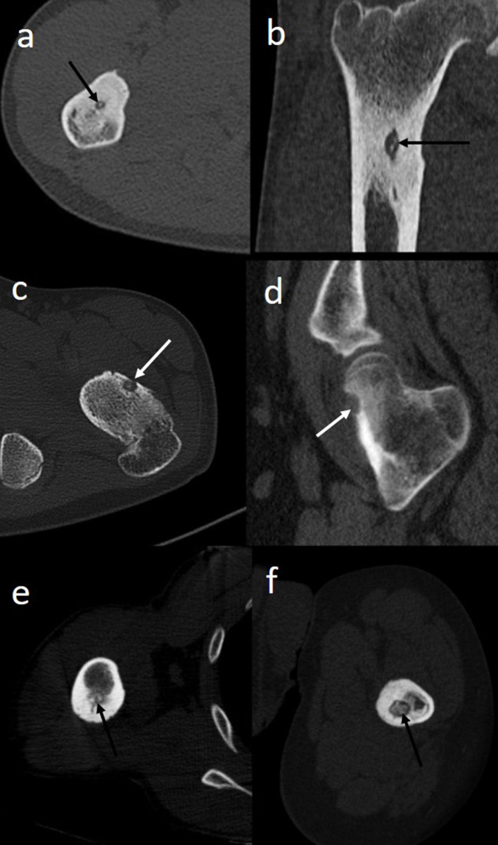
Osteoid osteoma is a benign osteoblastic skeletal tumour usually seen in the second and third decade of life with a male:female preponderance ranging from 2:1 to 4:1 as per various studies. It is a stage II tumour as per Musculoskeletal Society Staging system for benign tumours.1 This bone tumour accounts for approximately 10–13.5% of all benign bone tumours and 2–3% of all bone tumours.2–10 The most common site is meta-diaphyseal location of femur and tibia (50%). Less common sites include spine (10%), hands and feet.5,9,11,12 Osteoid osteoma can also be categorised according to location of nidus, that is, intra-articular or extra-articular, with further subdivisions into subperiosteal, cortical and intramedullary subtypes (Figure 1). The typical clinical presentation of osteoid osteoma is nocturnal pain at the site of involvement. The pain is readily relieved by anti-inflammatory agents, which has been attributed to inhibition of release of prostaglandin E2 and prostacyclins by the tumour.1,6,10–12 Intra-articular osteoid osteoma may have a different clinical presentation namely joint pain, decreased range of motion, gait or growth disturbances. Additionally, intra-articular osteoid osteoma of the proximal femur may present with referred pain over the knee.1,3–5,7,11,12
Figure 1.
(a–f): Different locations of osteoid osteoma. Axial (a) and coronal (b) images of an osteoid osteoma of proximal shaft of right femur in a 24-year-old male patient, showing an intramedullary radiolucent nidus (black arrows) with surrounding sclerosis. Axial (c) and sagittal (d) images of intra-articular osteoid osteoma of neck of left femur in a 26-year-old female showing nidus in the anterior subperiosteal location (white arrows). Minimal sclerosis is seen. Axial image of right humerus (e) of a 22-year-old male and left femur (f) of a 25-year-old male showing intra-cortical location of nidus (black arrows) with extensive surrounding sclerosis. Observe that different location of nidus is associated with variable amount of sclerosis, with intra-cortical osteoid osteoma usually showing extensive sclerosis whereas sub-periosteal osteoid osteoma showing minimal sclerosis.
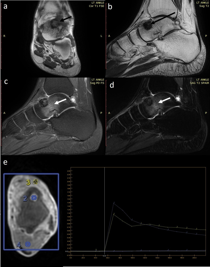
Osteoid osteoma consists of a centre or “nidus” of highly vascularised and innervated immature osteoid, enclosed by a rim of osteoblasts and surrounded by thickened trabecular bone on pathology. These findings are reflected on radiography and CT as a solitary radiolucent nidus with variable degree of surrounding sclerosis5,9,12–14 (Figure 1). The most important imaging findings for osteoid osteoma is the identification of nidus and assessment of nidus mineralisation, size and location. Nidus visualisation may be difficult on radiography in the presence of significant amount of sclerosis, commonly seen in cortical osteoid osteoma [Figure 1(e and f)]. A nidus size of less than 15 mm is highly suggestive of osteoid osteoma. Non-enhanced CT scan is the best modality for nidus assessment and estimation of adjacent sclerosis. On MRI, the nidus shows T1W isointense signal and variable T2W signal on comparison with adjacent normal muscle. T2W short tau inversion recovery sequence is extremely useful in estimating the perifocal bone oedema1,3,4,6,15[(Figure 2(a–d)]. Recently, virtual no calcium images obtained by dual energy CT has been found to have high diagnostic accuracy in the detection of osseous oedema.16 Contrast-enhanced CT and MRI although not necessary show enhancement of the unmineralised nidus and helps in increasing the diagnostic accuracy in indeterminate cases.3 Dynamic CE MRI shows typical kinetic features of nidal enhancement and further helps in diagnosis and localisation of osteoid osteoma17 (Figure 2e). Technetium (Tc) 99 bone scintigraphy findings of high central uptake with surrounding less uptake, commonly termed as “double density” sign, depicts nidus osteoblastic activity with associated host bone response. Tc 99 scintigraphy is highly sensitive for detection of osteoid osteoma and a negative, scintigraphy should prompt a MR evaluation to look for other causes.1,3,11,18,19
Figure 2.
(a–e) MRI evaluation of a 22-year-old male with osteoid osteoma of left talus. (a) Coronal T1-weighted (T1W) sequence shows that the lesion has an isointense centre and hypointense periphery (short black arrow). (b) The lesion is uniformly hypodense (long black arrow) on sagittal T2-weighted (T2W) sequences. Sagittal PDFS (c) and (d) T2W SPAIR sequence elegantly demonstrates the perilesional bone oedema (white arrows). (e) Axial dynamic CE MRI with region of interest (ROIs) placed on the lesion (ROI2), vessel (ROI3) and normal muscle (ROI4). Analysis shows that the lesion (blue curve) mimics the enhancement kinetics of the vessel (yellow curve) characteristic of nidus enhancement.
Management options of osteoid osteoma can be broadly classified as conservative, percutaneous image-guided treatment and surgical resection. Prolonged non-steroidal anti-inflammatory drug (NSAID) therapy is often associated with inadequate clinical response, drug-related renal and gastro-intestinal complications and drug intolerance. Excision of the entire nidus is critical for complete symptomatic relief. As intraoperative localisation of the nidus is usually difficult, the surgeon invariably resects surrounding sclerotic bone in order to achieve complete excision of nidus. Excessive removal of bone may lead to significant bone weakening, potentially necessitating bone graft procedures and increasing patient morbidity. Percutaneous image-guided procedures by either CT or MR guidance allow accurate nidus localisation resulting in clinical relief with minimal morbidity and without affecting bone strength. Nidus annihilation is achieved by either physical destruction with trephine needle or bone drill, ethanol ablation or thermal ablation. Thermal ablative procedures include radiofrequency ablation (RFA), microwave ablation and laser ablation. Excellent and rapid visualisation of the bone makes CT guidance superior to fluoroscopy, ultrasound and MRI for RFA of osteoid osteoma. CT fluoroscopy allows real-time needle guidance decreasing procedural time. CT-guided RFA is a rapid, percutaneous, minimally invasive, day-care interventional procedure which has treatment outcomes comparable to surgery. This procedure is technically more feasible at locations which are otherwise difficult to approach by surgery, for example acetabulum, intra-articular femur.1,3,5,11,12 This illustrative article will discuss a multidisciplinary management approach emphasising on patient selection, preoperative imaging diagnosis directed at treatment planning, imaging pitfalls, hardware selection, understanding the principle of needle guidance with “rail-road” technique,20 detailed step-by-step of RFA procedure, guidelines for prevention of complications and treatment follow-up.
Mechanism of RFA and understanding the treatment zone
RFA works by passing of high-frequency alternating current (>50 KHz) from a radiofrequency generator into the patient’s body through a non-insulated delivery probe. This passage of current increases ionic energy in the body tissue surrounding the delivery probe leading to increased ionic vibrations and subsequent loss of energy as heat. The thermal energy generated in the adjacent tissue induces tissue necrosis resulting in ablation. The area affected by this thermal energy is called “treatment zone” or “ablation zone.” The size and shape of the treatment zone is dependent on temperature and length of the non-insulated probe, design of the probe tip, amount of tissue charring and blood-flow-related heat dissipation. The RFA probe tip could be single electrode tip or multi-tined with the latter consisting of an assembly of multiple smaller electrodes emanating from a single, large port. The spatial arrangement of these small electrodes results in larger size and different shapes of treatment zone. Various studies have found that using a non-cooled probe length of 5–8 mm avoids heat transmission along the introducer while creating a treatment zone of 10–13 mm when heated to 90° C for 4–6 min. This treatment zone ensures selective nidus ablation while transmitting minimal heat to adjacent tissues, only if the delivery probe is accurately positioned within the nidus.2,3,9,11,12,21,22
Multidisciplinary management approach to osteoid osteoma
A clinico-radiological management team comprising of interventional radiologist, orthopaedic surgeon, anaesthesiologist specialised in pain medicine, specialised radiology technologist and nursing staff who are available in a single visit provides the best quality of care to osteoid osteoma patients.
Patient selection
Selection of patients is the most important step in achieving optimal treatment success. Clinical and performance status of the patient, patient comorbidities, imaging findings and risk of anaesthesia are critical factors which need to be assessed before considering CT-guided RFA as a possible treatment option.
Imaging diagnosis and pre-interventional clinico-radiological assessment
Typical clinical presentation of nocturnal pain responding to NSAIDs and characteristic imaging features of a nidus measuring less than 1.5 cm in size with adjacent variable sclerosis is diagnostic of osteoid osteoma. Nidus size of more than 1.5 cm should prompt the radiologist to consider other possibilities, for example osteoblastoma. A negative Tc 99 scintigraphy study rules out osteoid osteoma. CT and MRI are indicated in equivocal cases and in pre-procedural treatment planning. A biopsy should always be performed in cases where nidus is not visible or in presence of equivocal findings as histopathological confirmation is not possible after ablation. A biopsy of the lesion can be performed either as a separate sitting or in the same sitting as the RFA procedure or as a separate sitting. When biopsy is performed as a separate sitting before the RFA procedure, needle trajectory for the biopsy needle should be decided keeping in view the future CT-guided RFA trajectory in mind. A biopsy tract, which provides a central and perpendicular entry through the cortex into the lesion, provides an easy re-access route for CT-guided RFA.1–3,5,11
Once diagnosis of osteoid osteoma is confirmed by either imaging or histopathology, certain inclusion and exclusion criteria for CT-guided RFA as detailed in Table 1 should be considered. A written informed consent should be obtained from all patients. It should be made sure that the nidus is visible on CT or else other treatment options should be sought after. A detailed history enquiring about the site and severity of the pain should be obtained. Numerical Rating Scale (NRS) is an easy-to-use, verbal scale for pain assessment for patients aged 9 years or older.23 For children below 9 years of age, use of the Faces Pain Scale-Revised (FPS-R) is recommended.24 Patients with a score of 6 or more as per either NRS or score of 4 or more as per FPS-R25 with complaints of pain at the site of the lesion should be considered for CT-guided RFA. The tolerance capacity of the patient should also be noted in conjunction with pain assessment scale-based evaluation. Proximity of the lesion to skin, neurovascular bundle, cartilage and bowel is a critical imaging consideration. Inadvertent ablation of these vital structures may lead to complications namely skin burns, cartilage loss, nerve ablation or bowel injury.1–3,5 A nidus located within 10 mm from any of these structures should prompt alteration in either needle trajectory or consideration of other therapeutic option. In these special scenarios discussed in later sections of the article, various trajectory modifications can be adopted. These trajectory modifications are primarily aimed at increasing the effective distance from the nidus in order to exclude the vital structures away from the estimated treatment zone. Once appropriate trajectory and pre-treatment planning is decided in consultation with orthopaedic surgeon, laboratory investigations, pre-anaesthetic checkup is performed followed by appropriate hardware selection.
Basic laboratory investigations include complete blood count, blood sugar, prothrombin time, international normalised ratio (INR) should be obtained. An anaesthesiologist specialised in deep sedation/pain management should evaluate the patient and recommend further investigations if clinically indicated. Serious cardiovascular, neurological, renal or haematological chronic disease should be noted.
Hardware
Selection of appropriate hardware depends upon the location of the lesion and the needle approach.
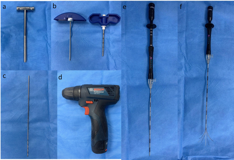
Hammer: A steel hammer of an appropriate size is generally used to advance the hard introducer towards the lesion (Figure 3a).
Hard introducer needle: This is a 11 gauge insulated co-axial needle with 1 cm markings which is manufactured in two sizes in 6 cm or 11 cm needle; 13 and 15 gauge co-axial needles are also available. This needle allows entry of both drill bits and RFA probe. For a hard introducer needle of a particular size, RFA probe of an appropriate length should be used. It should also be noted that once the RFA probe is opened, the tip of the RFA probe should be 7–8 mm away from the tip of the hard introducer needle for adequate ablation (Figure 3b).
Bone drill and drill bits: For deep-seated intramedullary lesions or lesions with extensive surrounding sclerosis, bone drilling is required to reach the nidus. Bone drill can be manual or electric. Appropriate size and length drill bit should be employed (Figure 3c–d).
RFA probe: RF probes are available in different probe length sizes usually as 5 mm or 10 mm. Both unipolar and bipolar RFA systems are available, with the former being more commonly used. Unipolar ablation system consists of two types of electrodes namely interstitial and dispersive electrodes or grounding pads. As previously discussed in the hardware section, the interstitial electrode may be single or multi-tined. The interstitial electrodes generate high current density within the tumour and subsequently produce heat energy. The high current density is subsequently dissipated through dispersive electrodes which have a large surface area to reduce soft tissue thermal injury. In contrast, in a bipolar ablation system, the current density generated is limited between the two electrodes, obviating the need of grounding pads. This results in rapid, localised heating of the area of interest. Due to this reason, it is crucial to accurately place the electrodes within the area of interest to ensure successful ablation. Bipolar ablation systems are often augmented with saline infusion mechanism to allow sustained delivery of current irrespective of local conductivity changes due to tissue necrosis. Non-cooled probes are preferred over cooled probes owing to higher incidence of pain in post-operative period and inaccurate estimation of treatment zones with cooled probes potentially leading to risk of inadequate ablation or other complications2,12,22(Figure 3e–f).
RF generator: Appropriate quality assurance and safety testing of the RF equipment should be performed.
Figure 3.
(a–f) A steel hammer which can be used to advance the introducer needle through thick bone. (b) A 6 inch introducer needle showing an insulated external hollow cylinder with 1 cm markings and the internal stylet with a diamond tip. (c) A 2×2 mm drill bit is commonly used in radiofrequency ablation of osteoid osteoma. The drill bit can be easily attached to the (d) battery-operated bone drill. Note that there are no markings on the drill bit. Careful manual measurements are required to advance the drill bit to the exact site of the lesion and to avoid drilling beyond the lesion. Multi-prong radiofrequency probe in (e) closed and (f) open state.
It is always a good practice to have a checklist of all the material and equipment (as detailed in Table 2) required before performing a procedure.
Table 2.
Pre-procedural checklist for CT-guided RFA
| Material required | Quantity | Please “tick the box” if arranged |
|---|---|---|
| Sterile bed sheet | 8 | |
| Leuckoplast | 1 | |
| Dynaplast | 1 | |
| Sterile disposable dressing pack (soft pack) | 5 | |
| Alcohol-based disinfectant | 1 | |
| Betadine | 1 | |
| Chlorhexidine | 1 | |
| 2% Lignocaine solution | 1 | |
| Spinal needle 20 G | 1 | |
| Hard introducer 6/11cm | 1 | |
| Hammer | 1 | |
| Drill gun | 1 | |
| Drill bit | 1 | |
| Sterile ruler | 1 | |
| Sterile protractor | 1 | |
| Grid | 1 | |
| Grounding pad | 1 | |
| Suture | 1 | |
| RF probe | 1 | |
| RF generator | 1 | |
| RFA cord | 1 | |
| Normal saline | 2 | |
| 2% dextrose | 1 | |
| Ringer’s lactate | 1 | |
| 10 ml Syringes | 10 | |
| Needle 18G | 10 | |
| 20 G IV cannula with IV set | 1 | |
| Anti-microbial paraffin gauze | 1 | |
| Personal protective equipment (Sterile gowns, sterile gloves, mask, head cap, shoe cover) | six of each (depending upon the number of persons in the operating CT suite) |
Table 1.
Clinico-radiological considerations in CT guided RFA3
| Clinical considerations | |
|---|---|
| 1 | Informed written consent |
| 2 | Pain intensity as per age-specific pain assessment methods |
| Imaging considerations | |
| 1 | Visibility of nidus on CT |
| 2 | Nidus size not more than 1.5 cm. |
| 3 | Distance of the nidus from skin. |
| 4 | Distance of the nidus from neurovascular bundle. |
| 5 | Distance of the nidus from cartilage. |
| 6 | Distance of the nidus from bowel. |
| Exclusion criteria | |
| 1 | Lesion not visible on CT |
| 2 | Lesion is complicated with fracture |
| 3 | Lesion is less than 10 mm away from skin, neurovascular bundle, cartilage, bowel |
| 4 | Active infection |
| 5 | Contraindication to anaesthesia |
| 6 | INR <1.3, Platelet count <50,000 |
| 7 | Contraindication to CT/ RFA: pregnancy |
| 8 | Serious cardiovascular, neurological, renal or haematological chronic disease |
CT RFA Suite
A CT-guided RFA suite should have designated place for handwashing, place for changing dress, a console room and the treatment area. A CT equipment with CT fluoroscopy capability provides lower radiation dose and reduces procedural time. Inside the treatment area, table for anaesthesia medication and equipment, radiofrequency equipment and other materials required during the procedure should be designated. Patient monitoring and support devices (like pulse oximetry, ECG, boy temperature, oxygen) should be appropriately placed. Institutional-specific sterilisation and infection control guidelines should be strictly followed and regulated timely.
Treatment planning and execution:
Patient should be fasting for 6–8 h before the procedure. Patient may be asked to empty his/her bladder before entering the treatment room. Patient-monitoring devices should be applied and an IV line is secured with a 20 gauge cannula.
Skin preparation: Shaving of the overlying skin with a depilatory cream lowers the risk of skin burns and reduces infection rates.
Position of the patient: A patient position which provides the shortest route of access from the skin and enables trajectory which is perpendicular to the plane of the lesion should be adopted. Patient position should be decided after reviewing pre-operative imaging studies and in consultation with the anaesthesiologist. Supine position is adopted in most cases. A lateral decubitus position may be preferred if the lesion is eccentrically located.
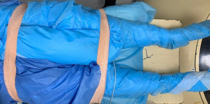
Application of grounding pads and appropriate padding: Grounding pads should be applied as per vendor-specific guidelines. For a lesion located in the proximal limb, for example thigh, grounding pad should be applied in the proximal portion. For lesions located in the distal limb, grounding pads maybe applied to the distal portion in the contralateral limb. The grounding pads should always be applied at the same level and care should be taken to avoid any air between the skin and the grounding pads. Subsequently, appropriate padding of areas of natural skin contact namely the axilla, groin and both limbs is performed. Only the operative site should be exposed while the rest of both limbs should be completely covered with drape sheets to avoid skin–skin contact. A pillow may also be placed in the groin region and the patient should be fixed with adhesive tape to the table (Figure 4). Any exposed metal surface on the CT table should also be covered with drape sheets to avoid skin to metal contact. This is also performed to avoid any patient related movement during the procedure.
Anaesthesia: Spinal anaesthesia is generally preferred in most cases. In patients with superficially located or subperiosteal lesions, total intravenous anaesthesia or local anesthesia with infiltration of periosteum may be considered. General anaesthesia is recommended in paediatric patients. Effective communication between the interventional radiologist and the anaesthesiologist is imperative to provide optimal anaesthesia to the patient.25 Prophylactic antibiotics may be administered as per institutional protocols.
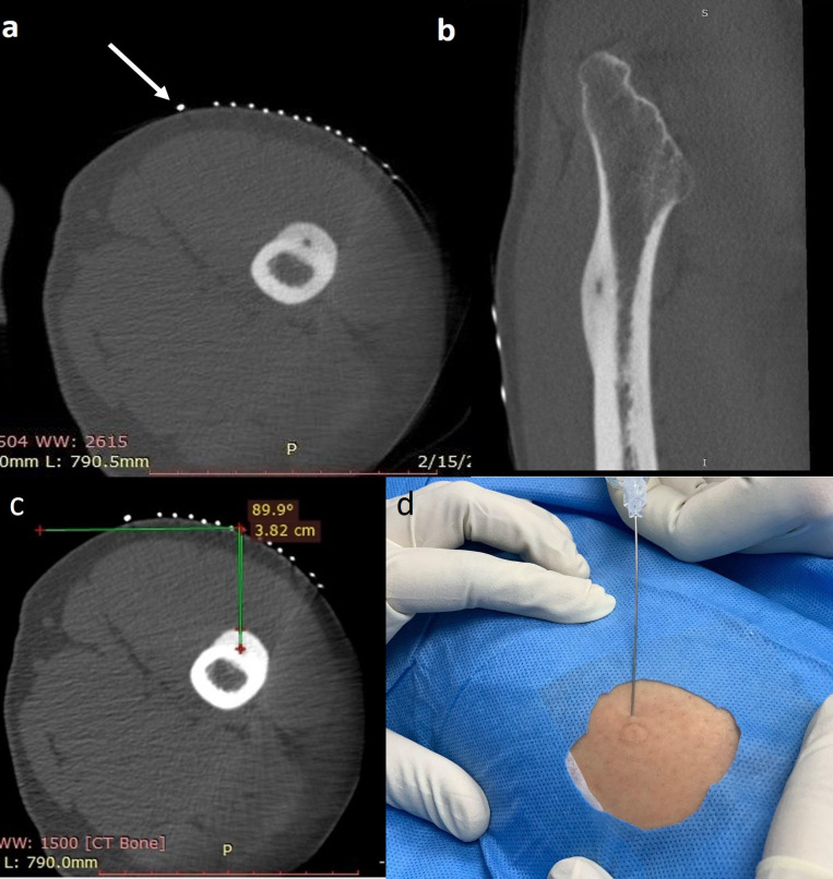
Placement of grid: A grid is a parallel arrangement of thin pins equidistant from each other. A grid should be placed before acquiring the first scan if the approximate site of the lesion can be ascertained. Use of a wide, short grid is beneficial as even approximate positioning over the lesion helps reduce radiation dose to the patient. The length of the grid preferably should be less than the circumference of the limb. It is suggested that one of the terminal pins of the grid should be appropriately thickened and placed in order to provide a sense of direction to the interventional radiologist (Figure 5a–b).
Recording of pin position, table position, distance and angle from the skin to bone: After placement of the grid and acquisition of first scan, entry site at the skin should be determined by counting the pin number and table position on the console. Distance of the skin to the bone surface and distance between the skin and the nidus should be measured and recorded. Angle of the estimated needle trajectory with the horizontal plane should also be recorded. A needle trajectory perpendicular to the plane of the lesion is always preferred (Figure 5c). The exact site of skin entry is marked on the patient subsequently using a needle hub. Alternatively, the site of skin entry can also be marked with a sterile pen. The grid is subsequently removed and appropriate skin cleaning is carried out using antiseptic agents like alcohol, chlorhexidine and betadine. The operative site is left to air-dry and draped using a sterile bed sheet. The skin is infiltrated with 2% lignocaine solution. (Figure 5d)
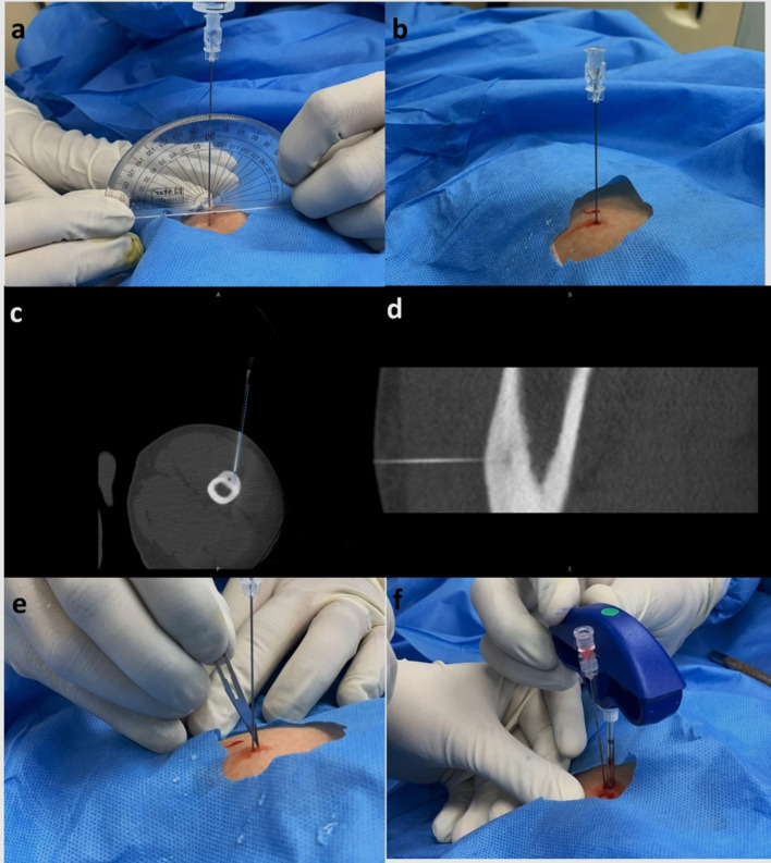
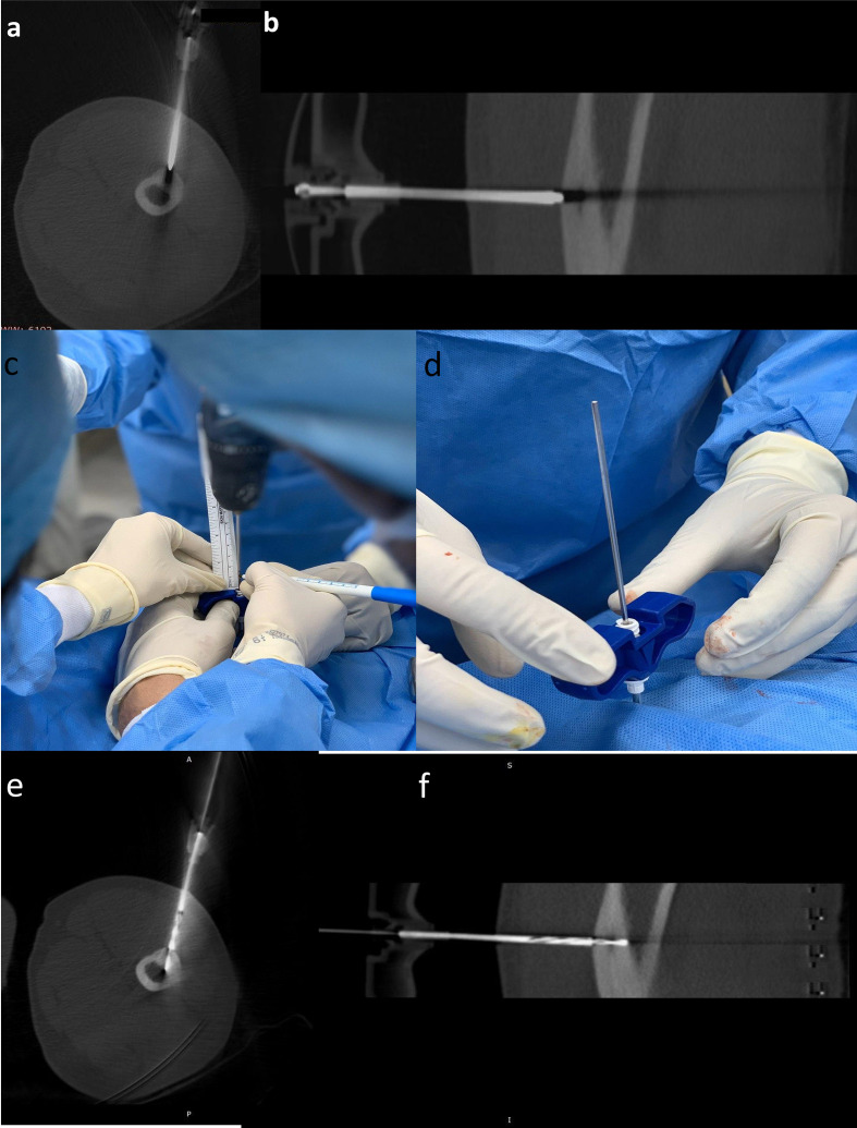
Concept of “rail-road” technique:This technique involves introduction of a spinal needle first from the designated point of skin entry up to the cortex overlying the lesion. Once accurate position of the spinal needle is achieved as determined on next scan. The thicker gauge-insulated needle is introduced using the already placed spinal needle as a “guide” wherein the introducer needle is advanced along the direction of spinal needle to the desired position (Figure 6). The introducer needle is anchored to the cortex using a hammer. The spinal needle is subsequently removed keeping the introducer needle in place. A scan is acquired to ascertain the position of introducer needle (Figure 7a and b). This technique reduces trajectory modifications resulting in less trauma and reduced procedural times.20
For subperiosteal osteoid osteomas, the introducer needle is anchored to the overlying cortex. For deep-seated lesions or lesions with significant sclerosis, drilling through the cortex and sclerotic bone may be required to advance the insulated needle into the nidus (Figure 7c–f). Drilling of bone or mere entry in the nidus can be extremely painful and optimal anaesthesia must be ensured before introducing the needle in the nidus.
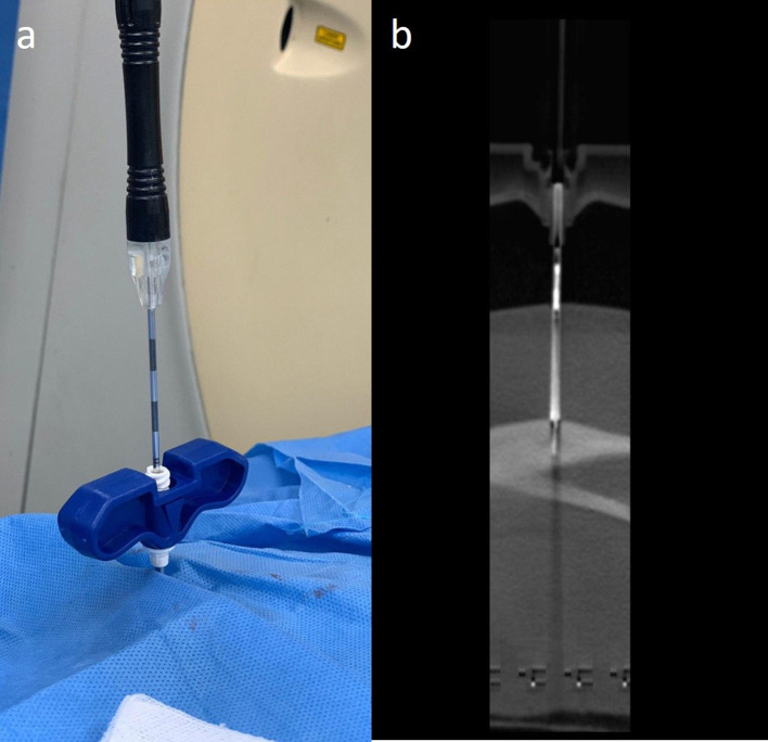
Introduction of the RF probe: One the nidus is accurately approached by the insulated introducer needle. In case the lesion is not confidently characterised as osteoid osteoma based on imaging and a biopsy is recommended after multi-disciplinary review, the stylet is carefully removed from the insulated needle and a biopsy is performed at this stage. Alternatively, if a biopsy is not required, the stylet is removed and the RF probe is introduced to a length where the unopened tip of the RF probe is flushed with the tip of the introducer needle (Figure 8). The RF probe is subsequently opened within the lesion and scan is acquired to ensure appropriate probe placement and estimation of the treatment zone. Care should be again taken that the estimated treatment zone does not include any vital structures.
Withdrawal of introducer needle till the level of cortex: Before commencing with RFA, it should be ensured that the active tip of the RF probe is not in contact with the introducer needle to avoid soft tissue burn injury. In case of intramedullary nidus, this is achieved by withdrawing the introducer needle from the lesion till the level of the overlying cortex while keeping the position of the RF probe tip unchanged within the nidus. This manoeuvre creates appropriate distance between the introducer needle and tip of the RF probe and thereby prevents thermal injury to the surrounding soft structures. In case of subperiosteal or intracortical lesions, the introducer needle is withdrawn up to the surface of the lesion, while keeping the position of the tip of RF probe unaltered within the centre of the nidus. Placement of normal saline soaked gauze pieces along the needle further helps in heat dissipation (Figure 9a).
RFA is carried out by achieving a temperature of 90° C and heating for a period of 4–6 min. The use of cooled probes may lead to inaccurate estimation of treatment zones.
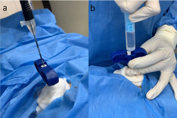
Once RFA is carried out and cooling of the RF probe is achieved. The RFA probe is subsequently closed and withdrawn back into the insulated needle. The entire RF probe–insulated needle complex is withdrawn as a unit in order to avoid thermal injury to adjacent structures. A solution of 2% lignocaine is injected along the tract aimed at reducing local site pain in the immediate post-operative period (Figure 9b). Skin suturing is performed if required and appropriate dressing is performed.
The total duration of the procedure is around 90 min including patient preparation, RFA and weaning off the patient from anaesthesia.
Figure 4.
Pre-procedural preparation showing optimal padding of a patient with osteoid osteoma of the right iliac bone. Grounding pads were applied first to both lower limb and complete padding of both lower limbs was performed. A pillow was placed between the groin to avoid skin contact. Both limbs were secured to the CT table to avoid any unwanted movement during the procedure.
Figure 5.
(a–d) Axial (a) and Sagittal (b) CT images of left femoral intracortical osteoid osteoma. The grid was already placed over the skin at the approximate site of the lesion prior to the first scan to reduce radiation dose. Notice that one pin (white arrow) is thickened as compared to the rest. As a convention at our institution, the thickened pin is always placed on the medial side of the patient in all radiofrequency ablation procedures. This allows prompt identification of medial and lateral side of the patient while planning the trajectory of the needle. (c) Recording of pin and calculation of distance and angle to the cortex overlying the lesion. A perpendicular trajectory is always preferred. (d) After marking the entry site on the skin by a needle hub, the grid is removed and the proper operative site skin cleansing is carried out and followed by local infiltration of 2% lignocaine solution.
Figure 6.
(a–f) Concept of rail-road technique. After marking the length on the spinal needle, (a) the needle is inserted at 90° to the lesion using a protractor, while simultaneously infiltrating local anaesthesia along the tissue planes till the bone is reached. (b) Once the needle is advanced till the bone, a scan is acquired to ascertain needle position. (c,d) Axial and sagittal CT image showing the spinal needle reaching up to the cortex overlying the nidus. Observe that the needle trajectory (dotted blue line) is slightly lateral to the location of the nidus. Keeping this in mind, (e) a small incision is made medial to the spinal needle and (f) the introducer needle is advanced along the spinal needle till the cortex. The spinal needle is subsequently removed.
Figure 7.
(a–f) Axial (a) and Sagittal (b) CT images showing the introducer needle anchored to the cortex overlying the nidus. Note that the needle tip artefact is crossing the nidus, confirming accurate position of the introducer needle. The distance between the tip of the needle and the nidus is measured. The drill bit-bone drill assembly is inserted after removing the stylet. In order to ensure that drilling is performed for the previously measured distance. A drop of betadine is used to mark the length of the drill bit required to reach the nidus (c). Once the visual betadine marker is at the brim of the introducer needle, (d) the drill gun is removed keeping the drill bit in place and a scan is acquired. Axial (e) and sagittal (f) CT images showing the tip of the drill bit within the nidus.
Figure 8.
(a, b) The drill gun is subsequently re-attached to the drill bit and the drill bit is removed. (a) RF probe is inserted and a scan is acquired. (b) Sagittal CT image showing the RF probe within the nidus of the lesion.
Figure 9.
(a,b) Placement of saline soaked gauze along the external stem of the introducer needle aimed at reducing the chances of skin burn. Once the radiofrequency ablation is completed. The RF probe is closed and withdrawn into the hard introducer. The hard introducer is removed while (b) simultaneously infiltrating 2% lignocaine along the tract to reduce immediate post-operative pain.
Post-interventional care
The patient should be placed under monitoring for a couple of hours. An anti-emetic agent, appropriate anti-pyretics, analgesic and 10% dextrose i.v. infusion should be administered in consultation with the anaesthesiologist. Appropriate pain assessment method should be used in the post-operative period. Patients can undergo weight bearing almost immediately and are usually discharged the same day. Patients can be recalled after a couple of weeks for pain assessment. A complete pain relief irrespective of change in imaging findings is indicative of treatment success. Incomplete ablation should be suspected in patients with residual pain. Radiographical features suggestive of ablation include infilling of the nidus and normalisation of bone density which may be seen within 2–27 months after treatment. However, there may be no change on imaging in certain cases.1,3
Treatment follow-up
A significant decrease in VAS score and absence of pain two years after the procedure is considered as “clinical success.” Imaging findings suggestive of successful ablation include resolution of bone oedema and perilesional synovial reaction, presence of bone remodelling and “ring sign.” Bone oedema, perilesional synovial reaction usually resolves by 1 year while complete bone remodelling may take up to 2 years (Figure 10). The “ring sign” is seen on MRI as presence of central hypointensity indicating necrosis with surrounding hyperintense rim suggestive of the demarcation zone between the healthy and necrotic tissue. Presence of this sign after the procedure indicates ablation within the tissue and is usually seen up to 6 months. MRI is usually preferred to CT for follow-up imaging as all the imaging findings can be seen on MRI. Additionally, dynamic CE MRI imaging can differentiate between residual nidus and nidus in healing stages based on different kinetic patterns. A residual radiolucency on radiographs or CT and persistent nidus enhancement following a pattern of initial rapid enhancement and washout during interstitial phase coupled with residual clinical pain are signs of incomplete ablation, 26–28 .
Figure 10.
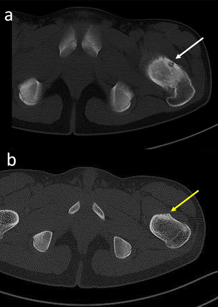
Follow-up CT post-radiofrequency ablation of osteoid osteoma. (a) Pre-interventional CT study showing a subperiosteal osteoid osteoma (white arrow) of left neck of femur. (b) Follow-up CT performed after 3 months shows that the nidus is completely replaced by sclerosis (yellow arrow).
Treatment consideration in large lesions
Nidus measuring more than 10 mm in size in any dimension may require RFA with multiple probe placements. Multiple probe placements lead to a cumulative larger treatment zones thereby increasing the chances of complete ablation. Overlap between treatment zones is preferred. Multiple probe placements can be achieved by positioning the tip of the RFA probe in both superficial and deep aspect of a lesion thereby creating at least two ablation zones with each probe. Multiple probes can also be used by creating two entry sites for a single lesion and abating the lesion with each probe one after the other in both superficial and deep planes.2,3
Treatment consideration in intra-articular or periarticular lesions
Intra-articular osteoid osteoma most commonly occurs in the hip joint. Trans-articular approach is more frequently associated with chondral damage, infection and inadequate treatment zone. Trans-articular approaches can be avoided in acetabular lesions but not in proximal femoral lesions. Care should be taken to avoid injury to the neurovascular bundle while introducing the needle through an anterior approach in proximal femoral lesions.
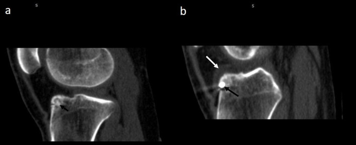
In peri-articular lesions, a minimum of 10 mm distance between the needle tip and the adjacent cartilage is recommended. Needle trajectory should be planned and appropriately angulated to achieve safe ablation. In our experience, creating an iatrogenic joint effusion by instilling fluid near the lesion before ablation ensures safer ablation2,3,7 (Figure 11). MR-guided focused ultrasound ablation therapy (MRgFUS) is an emerging alternative interventional radiology technique for the treatment of osteoid osteoma. This novel, needleless technique involves targeted delivery of multiple ultrasound beam or sonications consisting of small packets of energy to the lesion under MR-enabled thermal monitoring. This non-invasive method of ablation of osteoid osteoma has been found to have comparable efficacy to CT-guided RFA as per recent literature. Cannulating intra-articular or periarticular osteoid osteoma can be technically challenging in certain situations. Owing to its ability to perform highly focused non-invasive ablation without any radiation exposure or needle related damage to neurovascular bundle or articular cartilage, MRgFUS is ideal to perform ablation of osteoid osteoma around sensitive structures, especially in paediatric population.13,29–31
Figure 11.
(a,b) Creation of iatrogenic joint effusion during CT-guided radiofrequency ablation (RFA) of intra-articular osteoid osteoma. (a) Pre-intervention sagittal CT image of left knee showing intra-medllary nidus (short black arrow) located in the tibial plateau. (b) Sagittal CT image of RFA of osteoid osteoma showing the introducer needle (long black arrow) within the nidus. A peri-lesional joint effusion (white arrow) was created aimed to reducing heat transmission to surrounding structures.
Treatment consideration in osteoid osteomas of subcutaneous bones
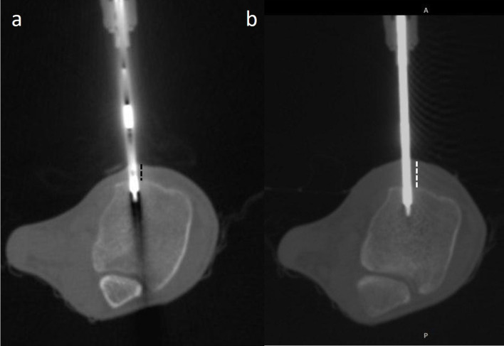
Osteoid osteomas of the subcutaneous bone, for example tibia, talus and of hand and feet, require special measures for ablation. Ablation in these locations has high rates for skin burn and injury to the neurovascular bundles. A minimum distance of 1 cm from the skin and neurovascular bundles should be followed while ablating these lesions. In case of osteoid osteoma of the finger, a minimum of 5 mm distance from the digital neurovascular bundle is recommended. Various procedural modifications are employed while ablation in these cases. These include use of specialised probes with smaller treatment zones and shorter ablation time of 3 min. Additionally, application of cold sponges over the skin during ablation and instillation of 2% dextrose solution into the subcutaneous plane (Figure 12) in order to increase the distance between the lesion and the skin is mentioned in the literature.2,3,14,32–34
Figure 12.
(a, b) CT-guided radiofrequency ablation of osteoid osteoma of tibia. (a) The distance between the probe tip and the skin is less (dotted black lines). (b) 10–15 ml of 2% lignocaine is infiltrated into the subcutaneous plane in order to increase the thickness of subcutaneous tissue (dotted white lines) and thereby increasing the probe tip to skin distance.
Treatment considerations in spinal lesions
Spinal osteoid osteomas account for 10% cases of all cases with posterior elements being the most common location. While ablating spinal osteoid osteomas, extreme care must be taken to avoid injury to neural elements, vessels and facet joint. A shelf of bone should always be present between the spinal cord and the tip of the probe. Various technical strategies including injection of sterile water or gas into the epidural space may be adopted while performing ablation. Recently, bipolar radiofrequency probes have been used in ablation of spinal osteoid osteomas which provide real-time monitoring of treatment zone volume and geometry. As discussed in the hardware section, bipolar ablation system provides fast and localised ablation without the need of grounding pads and are usually associated with cooling mechanism to ensure better local electrical conductivity. Additionally, navigational bipolar probe system has been designed in such a way that their distal segment can be curved in multiple directions.2,3,22,35–37
Conclusion
Osteoid osteoma is a common benign bone tumour seen in the younger population. This illustrative article provides a holistic multidisciplinary management approach and technical review of CT-guided RFA for the treatment of osteoid osteoma. Apart from providing a detailed discussion of established technical concepts, certain new ideas have been discussed which may prove beneficial in the management of osteoid osteoma. A pre-interventional checklist approach has been adopted to maximise work-flow efficiency. Adequate padding of the patient to avoid skin burns has been illustrated. While discussing the technique of CT-guided RFA, use of a protracter is illustrated to increase the accuracy of needle placement. Use of “rail-road technique” using a spinal needle which allows for exact lesion cannulation with minimal need for trajectory modifications has been deliberated in detail. Other technical modifications which may be useful in special situations have been considered. These include creation of iatrogenic joint effusion and subcutaneous effusion while performing ablation in intra-articular or periarticular osteoid osteoma and osteoid osteomas of subcutaneous bone, respectively.
Footnotes
Acknowledgements: 1. Mr. Gurudutt
Senior Radiographer, Department of Radiology and Imaging Vardhman Mahavir Medical College and Safdarjung Hospital, New Delhi
2. Mr. Ramesh
Senior Radiographer, Department of Radiology and Imaging Vardhman Mahavir Medical College and Safdarjung Hospital, New Delhi
3. Mr. Laxman Singh Mahar
Technical assistant, Department of Radiology and Imaging Vardhman Mahavir Medical College and Safdarjung Hospital, New Delhi
4. Mr. Baljeet Singh Yadav
Technical assistant, Department of Radiology and Imaging
Vardhman Mahavir Medical College and Safdarjung Hospital, New Delhi
5. Mr. Jasram
Technical assistant, Department of Anesthesia and Critical care.
Vardhman Mahavir Medical College and Safdarjung Hospital, New Delhi
Contributor Information
Amit Katyan, Email: akatyan9@gmail.com, amitkatyan@icloud.com.
Nishith Kumar, Email: drnishithkumar@rediffmail.com.
Kanchan Nigam, Email: kanchan050894@gmail.com.
Binita Jaiswal, Email: drbinitaj@gmail.com.
Ritu Nair Misra, Email: misraritu@gmail.com.
REFERENCES
- 1.Noordin S, Allana S, Hilal K, Nadeem N, Lakdawala R, Sadruddin A, et al. Osteoid osteoma: contemporary management. Orthop Rev 2018; 10: 7496PMID. doi: 10.4081/or.2018.7496 [DOI] [PMC free article] [PubMed] [Google Scholar]
- 2.Pinto CH, Taminiau AHM, Vanderschueren GM, Hogendoorn PCW, Bloem JL, Obermann WR. Technical considerations in CT-guided radiofrequency thermal ablation of osteoid osteoma: tricks of the trade. AJR Am J Roentgenol 2002; 179: 1633–42. doi: 10.2214/ajr.179.6.1791633 [DOI] [PubMed] [Google Scholar]
- 3.Motamedi D, Learch TJ, Ishimitsu DN, Motamedi K, Katz MD, Brien EW, et al. Thermal ablation of osteoid osteoma: overview and step-by-step guide. Radiographics 2009; 29: 2127–41. doi: 10.1148/rg.297095081 [DOI] [PubMed] [Google Scholar]
- 4.Chaudhry MBH, Salam B, Khandwala K, Sayani R, Muhammad A, Haq TU, et al. Image-Guided percutaneous radiofrequency ablation for osteoid osteoma: experience from a developing nation. Cureus 2019; 11: e5633: e5633. doi: 10.7759/cureus.5633 [DOI] [PMC free article] [PubMed] [Google Scholar]
- 5.Çakar M, Esenyel CZ, Seyran M, Tekin Ali Çağrı, Adaş M, Bayraktar MK, et al. Osteoid osteoma treated with radiofrequency ablation. Adv Orthop 2015; 2015: 1–5. doi: 10.1155/2015/807274 [DOI] [PMC free article] [PubMed] [Google Scholar]
- 6.Endo RR, Gama NF, Nakagawa SA, Tyng CJ, Chung WT, Pinto FFE. Osteoid osteoma – radiofrequency ablation treatment guided by computed tomography: a case series. Rev Bras Ortop Engl Ed.2017; 52: 337–43. [DOI] [PMC free article] [PubMed] [Google Scholar]
- 7.Marwan YA, Abatzoglou S, Esmaeel AA, Alqahtani SM, Alsulaimani SA, Tanzer M, et al. Hip arthroscopy for the management of osteoid osteoma of the acetabulum: a systematic review of the literature and case report. BMC Musculoskelet Disord 2015; 16: 318. doi: 10.1186/s12891-015-0779-8 [DOI] [PMC free article] [PubMed] [Google Scholar]
- 8.Maurer MH, Gebauer B, Wieners G, De Bucourt M, Renz DM, Hamm B, et al. Treatment of osteoid osteoma using CT-guided radiofrequency ablation versus MR-guided laser ablation: a cost comparison. Eur J Radiol 2012; 81: e1002–6. doi: 10.1016/j.ejrad.2012.07.010 [DOI] [PubMed] [Google Scholar]
- 9.Nijland H, Gerbers JG, Bulstra SK, Overbosch J, Stevens M, Jutte PC. Evaluation of accuracy and precision of CT-guidance in radiofrequency ablation for osteoid osteoma in 86 patients. PLoS One 2017; 12: e0169171. doi: 10.1371/journal.pone.0169171 [DOI] [PMC free article] [PubMed] [Google Scholar]
- 10.Venbrux AC, Montague BJ, Murphy KPJ, Bobonis LA, Washington SB, Soltes AP, et al. Image-Guided percutaneous radiofrequency ablation for osteoid osteomas. J Vasc Interv Radiol 2003; 14: 375–80. doi: 10.1097/01.RVI.0000058420.01661.8c [DOI] [PubMed] [Google Scholar]
- 11.Ghanem I. The management of osteoid osteoma: updates and controversies. Curr Opin Pediatr 2006; 18: 36–41. doi: 10.1097/01.mop.0000193277.47119.15 [DOI] [PubMed] [Google Scholar]
- 12.Cantwell CP, Kerr J, O'Byrne J, Eustace S. Mri features after radiofrequency ablation of osteoid osteoma with cooled probes and impedance-control energy delivery. AJR Am J Roentgenol 2006; 186: 1220–7. doi: 10.2214/AJR.05.0149 [DOI] [PubMed] [Google Scholar]
- 13.Temple MJ, Waspe AC, Amaral JG, Napoli A, LeBlang S, Ghanouni P, et al. Establishing a clinical service for the treatment of osteoid osteoma using magnetic resonance-guided focused ultrasound: overview and guidelines. J Ther Ultrasound 2016; 4: 16. doi: 10.1186/s40349-016-0059-6 [DOI] [PMC free article] [PubMed] [Google Scholar]
- 14.Albisinni U, Bazzocchi A, Bettelli G, Facchini G, Castiello E, Cavaciocchi M, et al. Treatment of osteoid osteoma of the elbow by radiofrequency thermal ablation. J Shoulder Elbow Surg 2014; 23: e1–7. doi: 10.1016/j.jse.2013.08.011 [DOI] [PubMed] [Google Scholar]
- 15.Kulkarni SS, Shetty NS, Polnaya AM, Janu A, Kumar S, Puri A, et al. Ct-Guided radiofrequency ablation in osteoid osteoma: result from a tertiary cancer centre in India. Indian J Radiol Imaging 2017; 27: 318. doi: 10.4103/ijri.IJRI_30_17 [DOI] [PMC free article] [PubMed] [Google Scholar]
- 16.Suh CH, Yun SJ, Jin W, Lee SH, Park SY, Ryu C-W. Diagnostic performance of dual-energy CT for the detection of bone marrow oedema: a systematic review and meta-analysis. Eur Radiol 2018; 28: 4182–94. Epub 2018 Apr 20. doi: 10.1007/s00330-018-5411-5 [DOI] [PubMed] [Google Scholar]
- 17.Liu PT, Chivers FS, Roberts CC, Schultz CJ, Beauchamp CP. Imaging of osteoid osteoma with dynamic gadolinium-enhanced MR imaging. Radiology 2003; 227: 691–700. doi: 10.1148/radiol.2273020111 [DOI] [PubMed] [Google Scholar]
- 18.Chahal A, Rajalakshmi P, Khan SA, Rastogi S, Srivastava DN, Gamanagatti S. Ct-Guided percutaneous radiofrequency ablation of osteoid osteoma: our experience in 87 patients. Indian J Radiol Imaging 2017; 27: 207–15. doi: 10.4103/ijri.IJRI_260_16 [DOI] [PMC free article] [PubMed] [Google Scholar]
- 19.Türkölmez S, Cayir D, Korkmaz M. Osteoid osteoma simulating osteomyelitis: differentiation with Tc-99m hig scintigraphy. Ann Nucl Med 2006; 20: 217–20. doi: 10.1007/BF03027433 [DOI] [PubMed] [Google Scholar]
- 20.Singh DK, Kumar N, Nayak BK, Jaiswal B, Tomar S, Mittal MK, et al. Approach-based techniques of CT-guided percutaneous vertebral biopsy. Diagn Interv Radiol 2020; 26: 143–6. doi: 10.5152/dir.2019.19268 [DOI] [PMC free article] [PubMed] [Google Scholar]
- 21.Asayama Y, Nishie A, Ishigami K, Kakihara D, Ushijima Y, Takayama Y, et al. Ct-Guided radiofrequency ablation of osteoid osteoma in the long bones of the lower extremity. World J Radiol 2012; 4: 278. doi: 10.4329/wjr.v4.i6.278 [DOI] [PMC free article] [PubMed] [Google Scholar]
- 22.Ahmed M, Brace CL, Lee FT, Goldberg SN. Principles of and advances in percutaneous ablation. Radiology 2011; 258: 351–69. doi: 10.1148/radiol.10081634 [DOI] [PMC free article] [PubMed] [Google Scholar]
- 23.von Baeyer CL. Numerical rating scale for self-report of pain intensity in children and adolescents: recent progress and further questions. Eur J Pain 2009; 13: 1005–7. doi: 10.1016/j.ejpain.2009.08.006 [DOI] [PubMed] [Google Scholar]
- 24.Tsze DS, von Baeyer CL, Bulloch B, Dayan PS. Validation of self-report pain scales in children. Pediatrics 2013; 132: e971–9. doi: 10.1542/peds.2013-1509 [DOI] [PMC free article] [PubMed] [Google Scholar]
- 25.Rimondi E, Mavrogenis AF, Rossi G, Ciminari R, Malaguti C, Tranfaglia C, et al. Radiofrequency ablation for non-spinal osteoid osteomas in 557 patients. Eur Radiol 2012; 22: 181–8. doi: 10.1007/s00330-011-2240-1 [DOI] [PubMed] [Google Scholar]
- 26.Arrigoni F, Bruno F, Gianneramo C, Palumbo P, Zugaro L, Zoccali C, et al. Evolution of the imaging features of osteoid osteoma treated with RFA or MRgFUS during a long-term follow-up: a pictorial review with clinical correlations. Radiol Med 2020; 125: 578–84Epub ahead of print. doi: 10.1007/s11547-020-01134-w [DOI] [PubMed] [Google Scholar]
- 27.Vanderschueren GM, Taminiau AHM, Obermann WR, van den Berg-Huysmans AA, Bloem JL, van Erkel AR, Huysmans A, Erkel A. The healing pattern of osteoid osteomas on computed tomography and magnetic resonance imaging after thermocoagulation. Skeletal Radiol 2007; 36: 813–21. doi: 10.1007/s00256-007-0319-1 [DOI] [PubMed] [Google Scholar]
- 28.Jankharia B, Burute N. Percutaneous radiofrequency ablation for osteoid osteoma: how we do it. Indian J Radiol Imaging 2009; 19: 36. doi: 10.4103/0971-3026.44523 [DOI] [PMC free article] [PubMed] [Google Scholar]
- 29.Arrigoni F, Napoli A, Bazzocchi A, Zugaro L, Scipione R, Bruno F, et al. Anzidei M2 & MercatelliD, Gravina GL, Zoccali C, Ghanouni P, Barile A, Catalano C, Masciocchi C. Magnetic-resonance-guided focused ultrasound treatment of non-spinal osteoid osteoma in children: multicentre experience. Pediatric Radiology 2019; 49: 1209–16. [DOI] [PubMed] [Google Scholar]
- 30.Arrigoni F, Bruno F, Palumbo P, Zugaro L, Zoccali C, Barile A, et al. Magnetic resonance-guided focused ultrasound surgery treatment of non-spinal intra-articular osteoblastoma: feasibility, safety, and outcomes in a single-center retrospective analysis. Int J Hyperthermia 2019; 36: 767–74. doi: 10.1080/02656736.2019.1639833 [DOI] [PubMed] [Google Scholar]
- 31.Geiger D, Napoli A, Conchiglia A, Gregori LM, Arrigoni F, Bazzocchi A, et al. MR-guided focused ultrasound (MRgFUS) ablation for the treatment of nonspinal osteoid osteoma: a prospective multicenter evaluation. J Bone Joint Surg Am 2014; 96: 743–5. doi: 10.2106/JBJS.M.00903 [DOI] [PubMed] [Google Scholar]
- 32.Ramos L, Santos JA, Santos G, Guiral J. Radiofrequency ablation in osteoid osteoma of the finger. J Hand Surg Am 2005; 30: 798–802. doi: 10.1016/j.jhsa.2005.03.009 [DOI] [PubMed] [Google Scholar]
- 33.Kuyumcu G, Sundaram M, Schils JP, Ilaslan H. Osteoid osteoma of the hand and foot in children successfully treated with radiofrequency neurotomy probes. Skeletal Radiol 2017; 46: 1561–5. doi: 10.1007/s00256-017-2702-x [DOI] [PubMed] [Google Scholar]
- 34.Lyon C, Buckwalter J. Case report: full-thickness skin necrosis after percutaneous radio-frequency ablation of a tibial osteoid osteoma. Iowa Orthop J 2008; 28: 85–7. [PMC free article] [PubMed] [Google Scholar]
- 35.Wang B, Han SB, Jiang L, Yuan HS, Liu C, Zhu B, et al. Percutaneous radiofrequency ablation for spinal osteoid osteoma and osteoblastoma. Eur Spine J 2017; 26: 1884–92. doi: 10.1007/s00586-017-5080-0 [DOI] [PubMed] [Google Scholar]
- 36.Tomasian A, Jennings JW. Spinal osteoid osteoma: percutaneous radiofrequency ablation using a navigational bipolar electrode system. American Journal of Roentgenology 2018; 211: 856–60. doi: 10.2214/AJR.17.19361 [DOI] [PubMed] [Google Scholar]
- 37.Faddoul J, Faddoul Y, Kobaiter-Maarrawi S, Moussa R, Rizk T, Nohra G, et al. Radiofrequency ablation of spinal osteoid osteoma: a prospective study. J Neurosurg Spine 2017; 26: 313–8. doi: 10.3171/2016.8.SPINE16462 [DOI] [PubMed] [Google Scholar]


