

Abstract
Objective.
We present a PNS oracle, which solves these computation time and linearity problems and is, therefore, well-suited for fast optimization of voltage distributions in contact electrode arrays and current drive patterns in non-contact magnetic coil arrays.
Approach.
The PNS oracle metric for a nerve fiber is computed from an electric field map using only linear operations (projection, differentiation, convolution, scaling). Due to its linearity, this PNS metric can be precomputed for a set of coil or electrode segments, allowing rapid PNS prediction and comparison of any possible coil or electrode stimulation configuration constructed from this set. The PNS oracle is closely related to the classical activating function and modified driving functions but is adjusted to better correlate with full neurodynamic modeling of myelinated mammalian nerves.
Main results.
We validated the PNS oracle in three MRI gradient coils and two body models and found good correlation between the PNS oracle and the full neurodynamic modeling approach (R2 > 0.995). Finally, we demonstrated its potential utility by optimizing the driving currents and voltages of arrays of 108 magnetic coils or 108 contact electrodes to selectively stimulate target nerves in the lower leg.
Significance.
Peripheral nerve stimulation (PNS) by electromagnetic fields can be accurately simulated using coupled electromagnetic and neurodynamic modeling. Such simulations are slow and non-linear in the electric field, which makes it difficult to iteratively optimize coil and electrode configurations or drive patterns aiming to avoid PNS or to initiate it for therapeutic purposes.
Keywords: selective peripheral nerve stimulation, target nerve, coil and surface electrode arrays, electromagnetic field simulation, magnetostimulation thresholds, MRI gradient coil switching, linear nerve model
Introduction
The ability to model and rapidly assess peripheral nerve stimulation (PNS) is becoming increasingly important for optimizing magneto-stimulation and electro-stimulation devices [13, 24, 48], as well as devices for which PNS is an unwanted side effect such as gradient coils in Magnetic Resonance Imaging (MRI) [3–5, 17] or drive coils in magnetic particle imaging (MPI) [14, 42]. In either case, the device designer must rapidly assess the efficiency with which a candidate electrode or coil design generates action potentials (APs) based on the electric fields (or electric potentials) generated in the body. While full titration studies using neurodynamic models of the nerves embedded in realistic electromagnetic body models have been proposed [11, 21, 28–30, 33, 35, 41] and were recently validated against experimental thresholds [12, 20], this workflow adds a lengthy computational step on top of the electromagnetic calculation.
Additionally, device optimization often divides the coil or electrode distribution into a set of discrete basis elements [19, 36, 46, 47], and because the total electromagnetic field is the superposition of the fields from individual coil or electrode elements, they can be computed as a weighted linear combination of those basis elements. The boundary element method stream function (BEM-SF) approach for designing coil winding patterns with desired field characteristics is an example of this approach which uses a set of current basis functions to compose all possible current patterns as a weighted combination of the basis functions [23, 31, 34]. A fast PNS predictor that is linear in the electric fields and thus the coil currents can be added to this approach to optimize nerve stimulation as well as the magnetic fields during an iterative coil design process. In this case, the PNS thresholds are assessed from a weighted linear sum of pre-computed PNS predictors which provides an important biological cost-function/constraint that can be incorporated into the optimization of the coil windings.
The activating function characterizes the temporal rate of change of the membrane potential at different sections of the nerve [37] and offers such a metric. Among other terms (including spatial characteristics of the nodes of Ranvier and non-linear ionic cur rents), the activating function for myelinated nerves incorporates the second spatial difference of the electric potential across neighboring nodes of Ranvier. This term is commonly referred to as modified driving function (MDF). While useful for identifying portions of a nerve that are likely to be stimulated, it is not a direct estimator of the stimulation thresholds of myelinated nerves. This is due to the fact that the MDF does not account for the differences in myelin thickness (which is a function of the axon diameter) or current redistribution between neighboring nodes of Ranvier for longer stimuli (current applied to a single node redistributes towards neighboring nodes, causing depolarization or hyperpolarization at these nodes). These limitations degrade the correlation of the MDF with the PNS thresholds. Improvements have been proposed to optimize this correlation: Warman et al [45] derived a semi-analytical linear threshold predictor based on an intracellular strength duration curve (obtained from an active nerve model) and the step response of a passive nerve model to an injected intracellular current. This approach yields a weighted sum of the MDF values at neighboring nodes of Ranvier, which provides more accurate estimates of stimulation thresholds for arbitrary applied source electric fields. However, this approach is not readily applicable to bi-polar stimuli (where different nerve sections are consecutively depolarized and hyperpolarized). Peterson et al [32] proposed a refined version of the kernel describing the nodal MDF weightings to better account for current redistribution and used a look-up table to infer the quantitative stimulation thresholds from this weighted MDF. The kernel was obtained by simulating the response of an active nerve model to a current injected into a single node of Ranvier. This significantly reduced the prediction error for simple electric field sources (such as single point electrodes) to <10%, but the model becomes inaccurate for complex sources (such as multiple point electrodes) with up to 45% threshold error. Howell et al [16] recently extended this approach by using a training dataset of nerve fibers with varying axon diameters excited by a DBS implant. The MDF kernel formulation as proposed by Peterson et al was adjusted by three parameters (offset, scaling and exponentiation) that were fitted to the stimulation thresholds of the training dataset (obtained from exciting an active nerve model). Although this improved the prediction accuracy in a majority of cases, significant outliers of threshold prediction accuracy could not be avoided (up to 50% error).
In this work, we propose an alternative approach in refining the kernel weights to improve the accuracy of threshold prediction, especially in terms of limiting outliers (reducing maximum prediction errors). We formulate our PNS oracle as a single linear function of the extracellular electric potentials and show that our PNS oracle achieves a correlation of R2 > 0.995 with the quantitative AP generation thresholds as determined from simulating neural responses in active nerve models. Finally, we demonstrate how to exploit the linearity of the PNS oracle for determining optimal strategies for selectively stimulating peripheral nerves using arrays of magnetic coils and surface electrodes.
Methods
The proposed PNS oracle is a MDF formulation designed for use with an electric field map obtained from coil or electrode components using electromagnetic simulations within body models. Each nerve segment in an atlas of nerve geometries is assigned a PNS oracle value for every element describing the current distribution or electrode configuration. The magnetostimulation or electrostimulation thresholds from the total electrode array or wire pattern are computed as the weighted sum of the oracles from individual stimulation basis elements. The use of the pre-computed oracle is in contrast to the combined electromagnetic and neurodynamic modeling described in previous PNS modeling frameworks [12, 20, 30].
In these full electromagnetic plus neurodynamic modeling frameworks, the electric fields induced by surface electrodes or by switching of magnetic coils are first simulated in realistic electromagnetic body models (figure 1). In a second step, the electric fields are projected onto the fibers of a nerve atlas co-registered to the body models. The projected electric fields are integrated to obtain the electric potentials along the nerves, which drive stimulation [27, 38, 39, 43, 44]. These potentials vary both spatially along the nerve as well as temporally since the electric potentials are linked to the coil current or electrode voltage waveform. Finally, the thresholds for AP generation are predicted by simulating the neural responses using a neurodynamic model of myelinated peripheral nerves to assess the minimum drive amplitude generating an AP. In this work, we replace the latter step, which is time-consuming and non-linear in the electric field, with a rapid estimation based on the PNS oracle [7].
Figure 1.

(A) Male and female body models with detailed peripheral nerve atlases used in our simulations (21 tissue classes, only bones, muscles and blood vessels are shown, approx. 1900 nerves per model). (B) Example of electric field pattern in transverse slice of the arm and a nerve fiber track (red dots indicate node of Ranvier positions). The nerve possesses a sharp kink (1) and runs through an electric field hot-spot (2). (C) Induced electric potential change along the nerve. (D) The MDF along the nerve exhibits two peaks, corresponding to the kink (1) and the E-field hot-spot (2).
Modified driving function
The electric potential along the nerve drives currents flowing along the axon. A change in axial current flow from one myelinated segment to the next requires a current flow between the intracellular and extracellular spaces, i.e. across the nerve’s membrane. This transmembrane current charges the membrane capacitance, thus changing the transmembrane voltage negatively (hyperpolarization) or positively (depolarization), with the latter eventually inducing an AP. The transmembrane current flow is proportional to the second spatial difference of the electric potential across the nodes of Ranvier [1, 37] (see figure 1(D)), which corresponds to the classical definition of the MDF for myelinated axons:
Here V (r) is the electric potential at position r along the nerve and L is the distance between neighboring nodes of Ranvier. A positive MDF represents current flows from the intracellular space to the extracellular space, and for a negative MDF, the nerve experiences the opposite transmembrane current. The MDF identifies portions of the nerve that are likely to be stimulated, however, this metric has a low correlation with stimulation thresholds and is therefore not well-suited for automatic electrode or coil winding optimization. Specifically, the MDF does not account for the effect of myelin thickness on the thresholds, or the crosstalk between neighboring nodes of Ranvier (current applied to a single node redistributes towards neighboring nodes), both effects are accounted for in the full neurodynamic model.
Neurodynamic modeling
A more accurate but computationally intensive assessment of the nerve response is to use electric circuit-based neurodynamic models of myelinated nerves to predict the time-course of the nerve’s membrane potentials. In our previously described PNS framework [8, 10, 12], we use the McIntyre–Richardson–Grill (MRG) model [25, 26, 40] that represents the nerve fiber by a double-cable equivalent electric circuit model. The PNS threshold (the smallest modulation waveform amplitude causing an AP) is obtained by repeatedly simulating the membrane dynamics at varying input amplitudes (titration). In our simulation, the titration process takes approx. 5 min for a typical nerve segment, and thus several days when simulating the entire nerve tree of our body models.
PNS oracle
We propose an adjusted MDF metric (the ‘PNS oracle’) as a surrogate for the titration process [7]. The PNS oracle retains the simplicity and linearity of the MDF (allowing for its rapid calculation) and increases the threshold prediction accuracy by including several corrections:
Here, K(D) is a smoothing kernel (which is a function of the axon diameter D), (*) is the convolution operator, L(D) is the node spacing and m(D) is a calibration factor accounting for the myelin thickness. The PNS oracle uses a step size L(D) equal to the distance between nodes of Ranvier (which itself is a function of the axon diameter D [2]) for evaluation of the finite difference, as was proposed before by Rattay and others [32, 37]. This has been shown to improve the quantification of the net transmembrane currents since almost all the voltage drop is across the node of Ranvier. Additionally, the PNS oracle smooths the electric potential’s second difference by a kernel K(D) to account for current redistribution between neighboring nodes of Ranvier, as proposed by Warman et al and others [32, 45]. Finally, the PNS oracle is weighted by a factor m(D) that models the increased excitability of large nerves (due to the thicker myelination of these nerves). The kernel K (D) and the normalization factor m(D) are calibrated for different axon diameters D and for a given current/voltage waveform: in this work, we used a 1 kHz sinusoidal waveform of 8 ms length (i.e. 8 sinusoidal lobes). All parameters of the PNS oracle can be found in the supplementary material.
Calibration and validation data.
We generated two sets of ‘test’ nerve fibers: one set was used for calibration of the PNS oracle parameters; a second set was used for validation. For the calibration set, we simulated the X and Y axes of three commercial MR gradient coils (2 body gradients, 1 head gradient), yielding a total of 6 coil winding patterns. For each winding pattern, we simulated both the female and male body model with the head at iso-center, resulting in 12 EM field simulations. These simulation setups correspond to the data used in our previous publication [12]. Finally, for each field simulation (i.e. ‘coil’—’body model’ combination), we assigned axon diameters of 8 μm, 10 μm, 12 μm, 16 μm, or 20 μm to all nerves. For each axon diameter, we chose 200 nerves with a diverse distribution of maximum MDF values (yielding a diverse distribution of PNS thresholds). This process generated a total of 12 000 nerve fibers (6 coils × 2 body models × 5 axon diameters × 200 nerves), for which we obtained individual PNS thresholds by simulating the neural responses using the full neurodynamic model. These PNS thresholds serve as the reference thresholds to calibrate the spatial kernel K (D) and the myelination calibration factor m(D). The validation set was generated using the same workflow but using the Z axes of the three analyzed gradient coils, yielding a set of 6000 nerve fibers along with their reference thresholds.
Calibration of convolution kernel K(D).
The convolution kernel characterizes the current redistribution across neighboring nodes of Ranvier. The kernel varies for different axon diameters D and different current/voltage waveforms. We used a two-step approach to determine these kernels: first, we obtained an initial guess of the kernel weights as outlined by Peterson et al [32], i.e. we used the MRG model to simulate the nerve response to a point-stimulus at a single node of Ranvier. The point stimulus was realized by injecting a current into the central node of Ranvier n0 and simulation of the neurodynamic response. The amount of current was chosen such that no AP was evoked. The injected current depolarized the respective node n0 as well as neighboring nodes n±1, n±2, n±3, etc due to current redistribution. The amount of depolarization of neighboring nodes relative to the depolarization of the central node determines the weights of the kernel:
We obtained these weights for a 1 kHz modulated current with an amplitude equivalent to 95% of the stimulation threshold. This approach yields a first estimation of the kernel weights, which we further refined using the reference PNS thresholds of the ‘test’ nerve fibers. More specifically, we optimized the kernel weights using Matlab’s fmincon so as to maximize the correlation (R2) between the reference PNS thresholds and the maximum inverse PNS oracle values. The calibration process and the resulting kernel weights are shown in figure S1 (stacks.iop.org/JNE/17/016029/mmedia) (supplementary material).
Calibration of normalization factor m(D).
The previously described steps (finite differencing with step size L(D), convolution with K (D)) achieve a good correlation with the reference PNS thresholds within one class of axon diameters. The final step removes this axon-diameter scaling by linear fitting of the ‘reference threshold’ versus the ‘inverse axon-dependent PNS oracle’. The slope of each linear fit, m(D), determined the normalization factors (see figure 4(B)). The calibration coefficient is normalized such that the PNS threshold is the inverse of the PNS oracle value, i.e. reducing the maximum PNS oracle of a nerve fiber by 50% doubles its PNS threshold. For MRI gradient simulations, it is useful to choose the normalization constant so that the PNS threshold computed from the oracle is expressed in convenient units (such as mT m−1 of gradient strength, or the current in Amperes injected into the windings). Thus, for the magnetostimulation work, we chose the oracle to have units of either m/mT or 1/A, although other conventions are possible.
Figure 4.

Reference PNS thresholds (obtained using the MRG neurodynamic model) for the 12 000 calibration nerves plotted against the inverse of the MDF (A), the inverse PNSO without the myelin calibration step (B), and the PNSO after applying the myelin calibration (C). Panel (D) shows the histogram of the relative error of the thresholds predicted using the PNSO. Panels (E) and (F) show the ‘reference threshold’ versus ‘inverse PNS oracle’ correlation and error histogram for the 6000 validation nerves (that were not used for calibration of the PNS oracle).
Application of the PNS oracle to targeted PNS
We demonstrate a potential use of the linear PNS oracle for electrode or coil design optimization by optimizing both an independently driven magnetic coil array and an electrode array to achieve selective stimulation of target peripheral nerves in the leg. The simulated coil array (figure 2(A)) consisted of 108 solenoid coils (50 windings, 5 cm diameter) equally distributed over the surface of a cylindrical former (height 65 cm, diameter 19 cm). For each coil element, we simulated the EM-fields in the leg of our male body model using Sim4Life’s magneto quasi-static solver on a hexahedral mesh (Sim4Life, Zurich MedTech). The field simulation was performed for a 1 kHz sinusoidal 1 A current fed to each coil separately. We computed the PNS oracle values along all nerves for each coil element’s electric field and assembled the results in an n × b matrix (n = number of nerve locations, b = number of coil elements). The same approach was used for an array consisting of 108 surface electrodes (roughly 2.5 cm diameter) placed in contact with the leg’s skin with one additional ground electrode (roughly 3 cm × 5 cm), see figure 2(B). The E-fields created by the electrodes were simulated by assigning an electrical potential of 1 V to one electrode at a time, while keeping all other electrodes (including the ground electrode) at 0 V. This approach yields a set of 108 electric field bases, which can be used to obtain the electric field induced by an arbitrary voltage configuration via a weighted sum of the electric field bases (as long as the ground electrode is kept at 0 V to define the reference voltage). The E-fields of this configuration were simulated using Sim4Life’s electro quasi-static solver (hexahedral mesh). The PNSO matrix of the electrode array was assembled similarly as for the magnetostimulation array.
Figure 2.
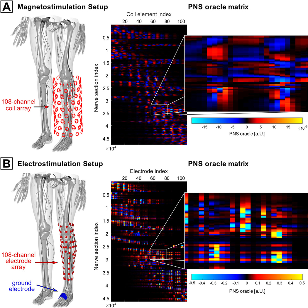
Setups used for targeted stimulation of peripheral nerves: (A) a coil array for magnetostimulation and (B) an array of contact electrodes for electrostimulation. The PNSO matrices are shown on the right side.
The right side of figure 2 shows the respective PNSO matrices for the magnetostimulation setup (panel A) and the electrostimulation setup (panel B) calculated for a 1 kHz sinewave input: the columns correspond to the 108 coils/electrodes while the rows correspond to different nerve sections in the leg. Note that the PNSO matrix for the magnetostimulation setup varies rather smoothly, whereas the electrostimulation PNSO matrix shows a higher dynamic range and numerous hot spots.
Using these pre-computed PNSO matrices, we performed a numerical optimization to identify the vectors x of optimal current and voltage weights achieving the greatest possible stimulation of a target nerve (i.e. high absolute PNS oracle values) while keeping stimulation in all other nerves below a desired tolerance value ϵ:
where PNSOtar denotes the PNSO matrix block that only includes the rows of the targeted nerves, and PNSOavd is the block corresponding to rows/nerves not to be stimulated. We characterize the stimulation selectivity S of a current/voltage vector x for a given target nerve by the ratio of the first and second terms in the above equation:
For example, a selectivity of S = 10 means that the target nerve is stimulated 10-fold stronger than the non-targeted nerves. We limited the maximum current for each coil array element to Imax = 5000A (which corresponds to a typical current amplitude used in TMS [15, 22]) and electrode voltages to Vmax = 10V. We demonstrate the current/voltage optimization for a set of seven target nerves with different sizes, fiber characteristics (sensory/motor), and locations within the leg (superficial/deep). The first target nerve (TN1) is a branch of the superficial sensory saphenous nerve. Target nerve TN2 is a small branch of the sensory medial sural nerve with a nearby large motor nerve (i.e. a more sensitive nerve that must not be stimulated). Targets TN3 and TN4 were chosen from a dense group of branches of the deep peroneal nerve (which is located at an intermediate depth in the leg). In this case, selective stimulation of the individual branches is challenging, as stimulation of other nearby branches need to be avoided. Finally, target nerves TN5 and TN6 are two branches of the motor tibial nerve, which is located deeply in the leg and ‘shielded’ by a large number of nerves for which stimulation must be avoided.
Results
PNS simulation workflow
Figure 1(B) shows the electric field for a transverse slice of the arm of the male body model (solid lines indicate tissue boundaries), including a typical nerve fiber path (red dots). Figure 1(C) shows the resulting potential change along the nerve fiber (obtained by projection and integration of the E-field), figure 1(D) shows the resulting MDF along the nerve. Note that at position (1), a kinked nerve segment passes through a homogeneous electric field whereas at position (2), a straight nerve segment passes through an electric field hotspot (where the field is highly inhomogeneous). In both cases, the relative orientation between nerve trajectory and electric field changes quickly, leading to sudden changes in the slope of the electric potential and thus peaks in the MDF.
Figure 3(A) shows the transmembrane potential computed using the full MRG model for the nerve shown in figure 1 as a function of position along the nerve (y -axis) over the time course of a sub-threshold sinusoidal current pulse (x-axis). The nerve is periodically hyperpolarized (green) and depolarized (red) at both positions 1 and 2 (i.e. at the two peaks of the nerve’s MDF), however, no APs are evoked. Increasing the coil current amplitude beyond the stimulation threshold (dashed red lines) induces APs that prop agate along the nerve (figure 3(B)). Note that the APs are induced at both positions 1 and 2. A single evaluation of the MRG model took approximately 15 s in this case.
Figure 3.

Transmembrane response of the nerve shown in figure 1 as a function of position along the nerve (y -axis) over the time-course (x-axis) of a sub-threshold sinusoidal stimulus (A) and a super-threshold sinusoidal stimulus (B). The nerve is periodically hyperpolarized (green) and depolarized (red) at both positions (1) and (2). In (B), four APs are clearly visible.
PNS oracle
Figure 4 shows the reference PNS thresholds (obtained using the full neurodynamic model) plotted against the inverse MDF for the calibration set (12 000 nerve fibers, the color indicates the axon diameter). While a general correlation exists, the MDF is clearly not an ideal surrogate for the full neurodynamic model. Figure 4(B) shows the reference thresholds plotted against the inverse PNS oracle after accounting for the current redistribution (convolution with K(D)), however, without incorporating the myelin calibration factor m(D). The PNS oracle correlates well with the reference thresholds within one class of axon diameters (R2 > 0.99 for all diameters). This axon-diameter dependence can be removed by linearly fitting each diameter class, and dividing the PNS oracle by the respective slope m(D) of the linear fit (which shifts all point clouds on top of each other). The result is shown in figure 4(C): the final PNS oracle achieves an excellent correlation with the reference thresholds of R2 = 0.995. Finally, figure 4(D) shows a histogram of the percentage threshold prediction error of the oracle (again compared to the reference thresholds). Figures 4(E) and (F) show the correlation between PNS oracles and reference thresholds and the error histogram for the validation dataset. The performance of the oracle in terms of R2 and error distribution is very similar for the calibration and validation sets and shows excellent prediction capability.
Figure 5 shows histograms of the PNS prediction error (percentage deviation from the reference thresholds) achieved by our PNS oracle (1) using the unoptimized kernel weights (i.e. as proposed by Peterson et al [32], shown in dashed grey) and (2) using the optimized kernel weights (red). Optimization of the kernel weights significantly reduces the maximum prediction error (from 29% to 18%) and the 95% confidence interval error (from 13.4% to 7.9%).
Figure 5.

Histogram of percentage threshold prediction errors (with respect to the reference thresholds) for all 18 000 test nerve fibers using the PNS oracle (red) and the approach proposed by Peterson et al (dashed grey). The PNS oracle reduces both the maximum prediction error (from 29% to 18%) and the 95% confidence interval error (from 13.4% to 7.9%).
Figure 6 shows PNS oracle hot spots overlaid to the nerve atlas of the male body model as induced by the three gradient axes of a body gradient (top) and a head gradient (bottom). For clarity only the 10% greatest hot-spots are shown. The body gradient primarily stimulates the shoulder nerves (via the Y axis) and intercostal nerves (via the Y and Z axes). The oracle hotspots in the shoulder reach a value of 46.7 m T−1, yielding an approximate PNS threshold of 1/46.7 m T−1 = 21.4 mT m−1 for the 1 kHz sinusoidal waveform. The head gradient primarily stimulates the facial nerves (especially in the forehead region) via the X axis, as well as intercostal nerves via the Z axis. In this case, the PNS oracle in the head reaches a value of 10 m T−1, which predicts a stimulation threshold of 1/10 m T−1 = 100 mT m−1.
Figure 6.

Hotspots of the PNS oracle induced by a body gradient (top) and a head gradient (bottom) in the male body model. Only the 10% greatest PNS oracle hotspots are shown for clarity.
Selective nerve stimulation using coil/electrode arrays
Figure 7 shows all target nerve stimulation results for the magnetostimulation coil array. For each target nerve, we show the location of the nerve in the body (1st row), the optimized current amplitudes and polarities of the 108 coil elements (2nd row), and the achieved PNS oracle distribution (3rd row).
Figure 7.
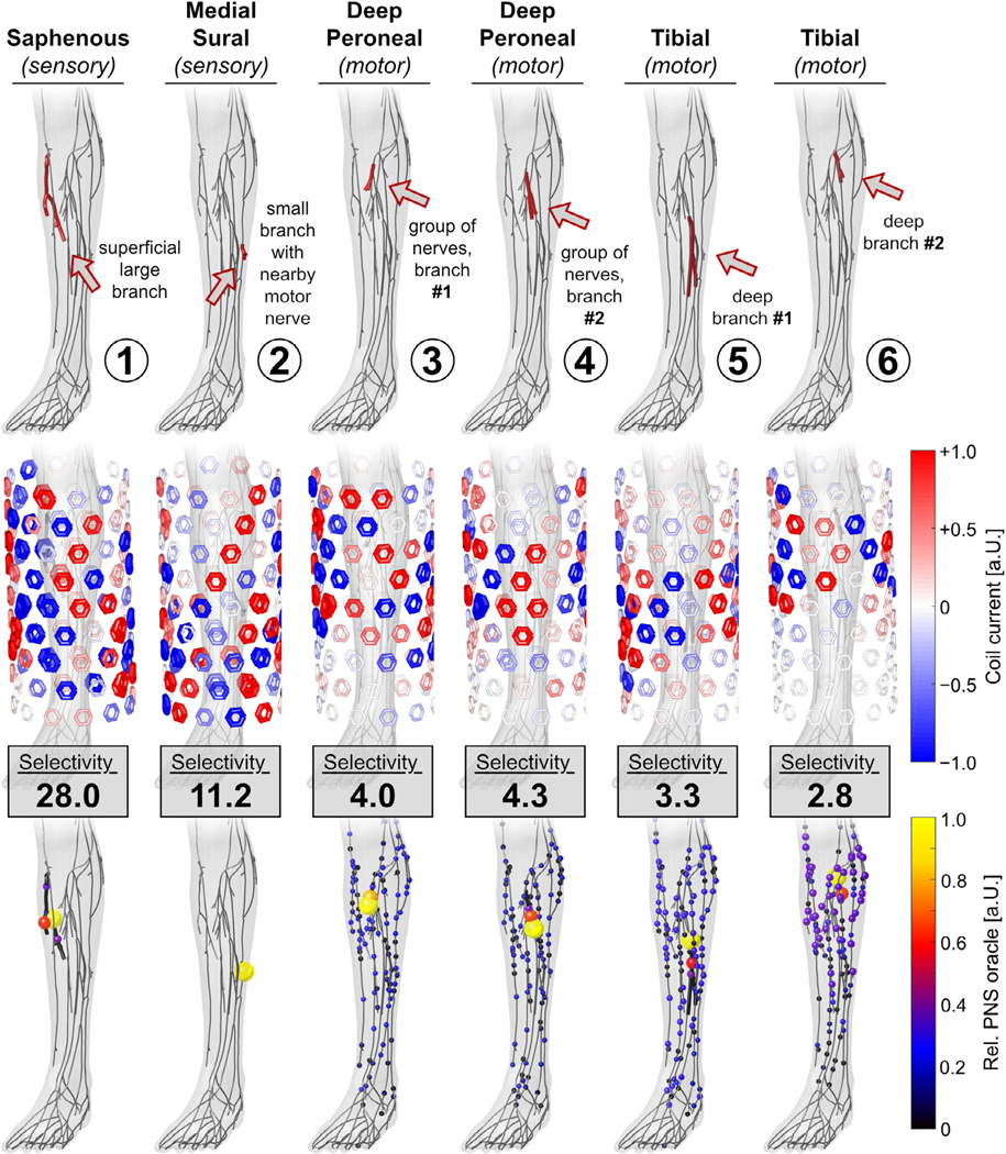
Performance of the magnetostimulation array for nerve stimulation in the leg in terms of optimized coil current amplitudes (2nd row) and the achieved PNS oracle hotspots (3rd row). Stimulation selectivity is reported as the ratio of maximum stimulation in the targeted and non-targeted nerves.
For target nerves located close to the surface (TN1 and TN2), the magnetic coil array achieved a selectivity of 28.0 and 11.2. This means that the target nerves are stimulated at least 11.2-fold more than the other nerves, hopefully allowing specific activation of the targeted nerve segments. Targeted stimulation becomes much more challenging for nerves at intermediate depths (TN3 and TN4) and great depths (TN5 and TN6): in this case, the selectivity drops to values between 2.8 and 4.0 because these branches are ‘shielded’ by the surrounding nerves. Even though the nerve targets TN3 and TN4 are located close to one another (approx. 1 cm), the coil array is capable of focusing stimulation to one of these two branches while avoiding stimulation of the other branches. For all nerve targets, the optimization algorithm energized a large number of coil elements (some of them reaching the 5000 A constraint).
Figure 8 shows the performance of the electrode array. The stimulation selectivity for the superficial nerves (TN1 and TN2) was 260.8 and 25.8, dropping to 11.0 and 2.2 for nerves at intermediate depths (TN3 and TN4) and to 1.8 and 3.0 for the nerves located deep in the leg (TN5 and TN6). Generally, for superficial nerve targets, the optimizer only used non-zero voltages for a few of the electrodes, whereas deeper nerves required many electrodes to be energized. For all target nerves, the optimizer employed rather small voltage amplitudes (≤3 V).
Figure 8.

Performance of the electrostimulation array for nerve stimulation in the leg in terms of optimized coil current amplitudes (2nd row) and the achieved PNS oracle hotspots (3rd row). Stimulation selectivity is reported as the ratio of maximum stimulation in the targeted and non-targeted nerves.
Discussion
We developed a refined surrogate for full neurodynamic modeling to allow rapid PNS assessment of complex magnetic coil distributions or electrode configurations. The PNS oracle (PNSO) is closely related to the classical activating function and MDF and retains their linearity with respect to the E-fields, but is adjusted to improve the correlation with reference stimulation thresholds obtained from active nerve models (yielding R2 > 0.995). Importantly, the PNS oracle is linear with respect to the E-field and thus linear with the applied coil currents or electrode voltages. We demonstrated that this linearity allows optimizing the coil currents and electrode voltages of stimulation arrays to achieve selective stimulation of peripheral nerves, even those located deep in the leg.
Calibration
Pre-computing the PNS oracle for individual coil or electrode elements allows rapid assessment of any given test configuration with respect to its PNS capabilities. The time-consuming neurodynamic simulations are only required during the oracle calibration. We used an extensive set of 12 000 nerves (6 coils × 2 body models × 5 axon diameter × 200 nerves) for this purpose, which should cover most typical nerve topologies in the human body. It is important to note that the PNS oracle calibration depends on the driving waveform (we used a 1 kHz sinusoid). For MRI gradient coil optimization, it might be sufficient to calibrate the oracle for two trapezoidal waveforms of different ramp times and use the linear relationship between the PNS thresholds and ramp times to extrapolate to arbitrary ramp times [17]. Magnetic or electric stimulation devices (like those studied in this work) usually apply short bipolar or monopolar pulses with little variation in the pulse lengths, suggesting that only a small number of calibration steps is needed in this case as well.
The PNS oracle calibration relies on the ability to accurately generate reference thresholds using a neurodynamic model. In this work, we use the well-established MRG model for myelinated mammalian nerve cells [25, 26, 40], but any model is a simplification of the nerve’s actual structure and physiology.
We have validated our PNS modeling framework in a previous work [6, 12] by comparing the simulated thresholds with group average experimental thresholds for a set of three MR gradient coils and found very good agreement with the experimental data (<10% threshold prediction error in all cases). This gives us a level of confidence in the modeling, although it does not absolutely guarantee its accuracy.
Oracle linearity
A key feature of the PNS oracle is that it is linear with respect to the electric field. This arises since the oracle formation only involves operations linear in the electric field (projection of the electric field onto the nerve, integration/derivation of the potentials, convolution). Firstly, this reduces the time needed to assess the PNS characteristics of a single nerve segment to milliseconds (compared to minutes needed for repeatedly simulating the neural responses of active nerve models). Secondly, the stimulation capability of a set of electrodes, coils, or wire segments can be expressed as a linear combination of the stimulation induced by each basis element individually. Although precomputation of the oracle for all the coils or electrodes in the array can be time-consuming, once this is done any drive pattern for the array can be rapidly checked. We used this feature to optimize the waveform amplitudes of individually driven coils/electrodes to achieve stimulation of target nerves in the lower leg, while avoiding stimulation in all other nerves.
The magnetic coil array achieved stimulation selectivity (ratio of maximum PNS oracles in the targeted and non-targeted nerves) ranging between 2.8 and 28.0 depending on the nerve depth. The deeper the nerve, the more shielded it is from an EM perspective and by the other nerves nearby, thus making it harder to stimulate selectively. Similarly, the stimulation selectivity of the contact electrode array was large for superficial nerves (up to 260.8) and slightly lower for deep nerves (1.8–3.0) which is likely due to the fact that electrodes create highly localized E-field patterns that quickly drop in intensity as a function of tissue depth. As a consequence, the electrode array was less able to selectively stimulate deep and intermediate-depths nerves. The difference in stimulation depth pattern is somewhat visible in the plot of the PNSO matrices in figure 2: the coil array’s PNSO matrix varies rather smoothly, whereas the electrode array’s PNSO matrix shows various hot spots. This indicates that the electrode and coil arrays are complementary and that a more ideal configuration may be to combine both types of elements in a single array. Finally, we point out that our choice of electrode configurations (one active while all others set to 0 V) only covers a small portion of all possible electrode voltage combinations. For example, this ‘canonical basis’ of electrode configuration does not include disconnection of electrodes, whereby the current cannot flow (this is different from setting the voltage to 0 V or ground). Although it is not practical to compute the EM fields for all possible electrode drive configurations of the active (1 V), grounded (0 V), and disconnected states, this additional degree-of-freedom may allow shaping more localized electric current paths, which may in turn allow achieving higher stimulation selectivity.
Limitations of coil/electrode simulations
A limitation of our study is that we did not address the robustness of selective PNS by external coil or electrode arrays. This includes assessing the robustness of the optimized coil/electrode configurations to variations among individuals, position of the coil or electrode arrays relative to the patient, patient movements or uncertainties in body anatomy and nerve trajectories (both of which affect the E-field and its interaction with the nerves), only to name a few. We have recently performed a sensitivity analysis of our previously published PNS simulation framework [18], where we investigated the impact of important simulation parameters (such as electromagnetic tissue properties, spatial resolutions used for the EM field simulations and body model placement relative to the coil) on the PNS thresholds predicted by the neurodynamic model. In this sensitivity analysis, we found that most of the simulation parameters can be controlled to yield acceptable variations of PNS thresholds (approx. 5%). Although many of these results can be translated to the accuracy of the PNS oracle and its application to selective nerve stimulations, a more in-depth analysis of the robustness of this approach is needed.
Application to MR gradients
Another application of the PNS oracle is the design optimization of coil winding patterns whose primary function is the generation of a certain B-field pattern [23, 31, 34], and where PNS is an unwanted effect (such as a linear gradient field in MRI). In this design optimization, a nerve stimulation metric which is linear in the applied current can be used in the optimization cost function or constraint allowing the direct incorporation of PNS into the winding optimization. In this formulation, the PNS oracle can be pre-computed for each current basis function used in the optimization and incorporated as a linear penalty matrix to enforce PNS-optimized coil layouts. We have recently demonstrated that this reduces the PNS capabilities of a typical whole-body MR gradient design by a factor of 2, potentially doubling the speed at which the gradient fields can be safely switched without causing PNS [9].
Conclusion
We presented an approach to quickly and accurately estimate PNS thresholds without the need to simulate the complex neurodynamics of the nerve fibers. The PNS oracle is computed from the potential changes along the nerve paths using only linear operations, which dramatically speeds up computation (factor ×1000 compared to the full neurodynamic model). This linearity allows simple addition of precomputed PNS oracles associated with wire segments and electrodes to formulate the total oracle for coil or electrode configurations (similar to the superposition principle of the EM fields). By design, the PNS threshold for the test waveform is the inverse of the oracle. We believe that the PNS oracle will prove a powerful tool for designing and operating stimulation devices or to improve coil layouts such as MRI gradient coils where unwanted stimulations have become a significant limitation.
Supplementary Material
Acknowledgments
Research was supported by the National Institute of Biomedical Imaging and Bioengineering of the National Institutes of Health under award numbers R00EB019482, U01EB025121, and U01EB025162. The content is solely the responsibility of the authors and does not represent the official views of the National Institutes of Health.
References
- [1].Basser P J, Wijesinghe R S and Roth B J 1992. The activating function for magnetic stimulation derived from a three-dimensional volume conductor model IEEE Trans. Biomed. Eng. 39 1207–10 [DOI] [PubMed] [Google Scholar]
- [2].Basser P J 2004. Scaling laws for myelinated axons derived from an electronic core-conductor model J. Integr. Neurosci. 03 227–44 [DOI] [PubMed] [Google Scholar]
- [3].Budinger T F 1979. Thresholds for physiological effects due to RF and magnetic fields used in NMR imaging IEEE Trans. Nucl. Sci. 26 2821–5 [Google Scholar]
- [4].Cohen M S, Weisskoff R M, Rzedzian R R and Kantor H L 1990. Sensory stimulation by time-varying magnetic fields Magn. Reson. Med. 14 409–14 [DOI] [PubMed] [Google Scholar]
- [5].Cohen M S, Weisskoff R and Kantor H 1989. Evidence of peripheral stimulation by time-varying magnetic fields Proc. of the 75th anniversary Sci. Assem. Ann. Meeting Radiol Soc. of North America (Abstracts) [Google Scholar]
- [6].Davids M, Guérin B, Klein V, Schad L R and Wald L L 2018. Simulation of peripheral nerve stimulation thresholds of MRI gradient coils Proc. of the 26th Annual Meeting of ISMRM (Paris, France) [Google Scholar]
- [7].Davids M, Guérin B, Klein V, Schad L R and Wald L L 2019. The PNS oracle: a modified neural activation function metric for rapid assessment of peripheral nerve stimulation (PNS) Proc. of the 27th Annual Meeting of ISMRM (Montreal, Canada) [Google Scholar]
- [8].Davids M, Guérin B, Schad L R and Wald L L 2017. Predicting magnetostimulation thresholds in the peripheral nervous system using realistic body models Sci. Rep. 7 5316. [DOI] [PMC free article] [PubMed] [Google Scholar]
- [9].Davids M, Guérin B, Schad L R and Wald L L 2019. Peripheral nerve stimulation (PNS) constrained gradient coil design within a boundary element method stream function (BEMSF) optimization Proc. of the 27th Annual Meeting of ISMRM (Montreal, Canada) [Google Scholar]
- [10].Davids M, Guérin B, Schad L R and Wald L L 2019. Prediction of peripheral nerve stimulation thresholds of MRI gradient coils using coupled electromagnetic and neurodynamic simulations Proc. of the 27th Annual Meeting of ISMRM, Montreal (Canada) [DOI] [PMC free article] [PubMed] [Google Scholar]
- [11].Davids M, Guérin B, Schad L R and Wald L L 2019. Peripheral Nerve Stimulation Modeling for MRI (New York: eMagRes; ) pp 87–102 [Google Scholar]
- [12].Davids M, Guérin B, vom Endt A, Schad L R and Wald L L 2019. Prediction of peripheral nerve stimulation thresholds of MRI gradient coils using coupled electromagnetic and neurodynamic simulations Magn. Reson. Med. 81 686–701 [DOI] [PMC free article] [PubMed] [Google Scholar]
- [13].Fisher L E, Tyler D J and Triolo R J 2013. Optimization of selective stimulation parameters for multi-contact electrodes J. Neuroeng. Rehabil. 10 25. [DOI] [PMC free article] [PubMed] [Google Scholar]
- [14].Gleich B and Weizenecker J 2005. Tomographic imaging using the nonlinear response of magnetic particles Nature 435 1214–7 [DOI] [PubMed] [Google Scholar]
- [15].Groppa S et al. 2012. A practical guide to diagnostic transcranial magnetic stimulation: report of an IFCN committee Clin. Neurophysiol. 123 858–82 [DOI] [PMC free article] [PubMed] [Google Scholar]
- [16].Howell B, Gunalan K and McIntyre C C 2019. A driving-force predictor for estimating pathway activation in patient-specific models of deep brain stimulation Neuromodulation 22 403–15 [DOI] [PMC free article] [PubMed] [Google Scholar]
- [17].Irnich W and Schmitt F 1995. Magnetostimulation in MRI Magn. Reson. Med. 33 619–23 [DOI] [PubMed] [Google Scholar]
- [18].Klein V, Davids M, Wald L L, Schad L R and Guérin B 2018. Sensitivity analysis of neurodynamic and electromagnetic simulation parameters for robust prediction of peripheral nerve stimulation Phys. Med. Biol. 64 015005. [DOI] [PMC free article] [PubMed] [Google Scholar]
- [19].Kosta P, Warren D J and Lazzi G 2019. Selective stimulation of rat sciatic nerve using an array of mm-size magnetic coils: a simulation study Healthcare Technol. Lett. 6 70–5 [DOI] [PMC free article] [PubMed] [Google Scholar]
- [20].Laakso I, Matsumoto H, Hirata A, Terao Y, Hanajima R and Ugawa Y 2014. Multi-scale simulations predict responses to non-invasive nerve root stimulation J. Neural Eng. 11 056013. [DOI] [PubMed] [Google Scholar]
- [21].Ladenbauer J, Minassian K, Hofstoetter U S, Dimitrijevic M R and Rattay F 2010. Stimulation of the human lumbar spinal cord with implanted and surface electrodes: a computer simulation study IEEE Trans. Neural Syst. Rehabil. Eng. 18 637–45 [DOI] [PubMed] [Google Scholar]
- [22].Lefaucheur J-P 2008. Use of repetitive transcranial magnetic stimulation in pain relief Exp. Rev. Neurother. 8 799–808 [DOI] [PubMed] [Google Scholar]
- [23].Lemdiasov R A and Ludwig R 2005. A stream function method for gradient coil design Concepts Magn. Reson. 26B 67–80 [Google Scholar]
- [24].McDonnall D, Clark G A and Normann R A 2004. Selective motor unit recruitment via intrafascicular multielectrode stimulation Can. J. Physiol. Pharmacol. 82 599–609 [DOI] [PubMed] [Google Scholar]
- [25].McIntyre C C and Grill M W 1998. Sensitivity analysis of a model of mammalian neural membrane Biol. Cybern. 79 29–37 [DOI] [PubMed] [Google Scholar]
- [26].McIntyre C C, Richardson A G and Grill W M 2002. Modeling the excitability of mammalian nerve fibers: influence of afterpotentials on the recovery cycle J. Neurophysiol. 87 995–1006 [DOI] [PubMed] [Google Scholar]
- [27].McNeal D R 1976. Analysis of a model for excitation of myelinated nerve IEEE Trans. Biomed. Eng. 23 329–37 [DOI] [PubMed] [Google Scholar]
- [28].Mourdoukoutas A P, Truong D Q, Adair D K, Simon B J and Bikson M 2018. High-resolution multi-scale computational model for non-invasive cervical vagus nerve stimulation Neuromodulation 21 261–8 [DOI] [PMC free article] [PubMed] [Google Scholar]
- [29].Neufeld E, Cassará A M, Montanaro H, Kuster N and Kainz W 2016. Functionalized anatomical models for EM-neuron interaction modeling Phys. Med. Bio. 61 4390–401 [DOI] [PMC free article] [PubMed] [Google Scholar]
- [30].Neufeld E, Oikonomidis I V, Iacono M I, Angelone L M, Kainz W and Kuster N 2016. Investigation of assumptions underlying current safety guidelines on EM-induced nerve stimulation Phys. Med. Biol. 61 4466–78 [DOI] [PMC free article] [PubMed] [Google Scholar]
- [31].Peeren G N 2003. Stream function approach for determining optimal surface currents J. Comput. Phys. 191 305–21 [Google Scholar]
- [32].Peterson E J, Izad O and Tyler D J 2011. Predicting myelinated axon activation using spatial characteristics of the extracellular field J. Neural Eng. 8 046030. [DOI] [PMC free article] [PubMed] [Google Scholar]
- [33].Pisa S 2014. A complete model for the evaluation of the magnetic stimulation of peripheral nerves Open Biomed. Eng. J. 8 1–12 [DOI] [PMC free article] [PubMed] [Google Scholar]
- [34].Poole M and Bowtell R 2007. Novel gradient coils designed using a boundary element method Concepts Magn. Reson. 31 162–75 [Google Scholar]
- [35].RamRakhyani A K, Kagan Z B, Warren D J, Normann R A and Lazzi G 2015. A μm-scale computational model of magnetic neural stimulation in multifascicular peripheral nerves IEEE Trans. Biomed. Eng. 62 2837–49 [DOI] [PubMed] [Google Scholar]
- [36].Raspopovic S, Capogrosso M, Badia J, Navarro X and Micera S 2012. Experimental validation of a hybrid computational model for selective stimulation using transverse intrafascicular multichannel electrodes IEEE Trans. Neural Syst. Rehabil. Eng. 20 395–404 [DOI] [PubMed] [Google Scholar]
- [37].Rattay F 1986. Analysis of models for external stimulation of axons IEEE Trans. Biomed. Eng. 33 974–7 [DOI] [PubMed] [Google Scholar]
- [38].Reilly J P 1989. Peripheral nerve stimulation by induced electric currents: exposure to time-varying magnetic fields Med. Biol. Eng. Comput. 27 101–10 [DOI] [PubMed] [Google Scholar]
- [39].Reilly J P, Freeman V T and Larkin W D 1985. Sensory effects of transient electrical stimulation—evaluation with a neuroelectric model IEEE Trans. Biomed. Eng. 32 1001–11 [DOI] [PubMed] [Google Scholar]
- [40].Richardson A G, McIntyre C C and Grill W M 2000. Modelling the effects of electric fields on nerve fibres: influence of the myelin sheath Med. Biol. Eng. Comput. 38 438–46 [DOI] [PubMed] [Google Scholar]
- [41].Samoudi A M, Kampusch S, Tanghe E, Széles J C, Martens L, Kaniusas E and Joseph W 2017. Numerical modeling of percutaneous auricular vagus nerve stimulation: a realistic 3D model to evaluate sensitivity of neural activation to electrode position Med. Biol. Eng. Comput. 55 1763–72 [DOI] [PubMed] [Google Scholar]
- [42].Saritas E U, Goodwill P W, Zhang G Z and Conolly S M 2013. Magnetostimulation limits in magnetic particle imaging IEEE Trans. Med. Imaging 32 1600–10 [DOI] [PubMed] [Google Scholar]
- [43].Sweeney J D, Deng K, Warman E and Mortimer J T 1989. Modeling of electric field effects on the excitability of myelinated motor nerve Images of the Twenty-First Century. Proc. of the Ann. Int. Eng. Med. Biol. Soc. vol 4, pp 1281–2 [Google Scholar]
- [44].Sweeney J D, Mortimer J T and Durand D 1987. Modeling of mammalian myelinated nerve for functional neuromuscular stimulation IEEE/Eng. Med. Biol. Soc. Ann. Conf. (IEEE) [Google Scholar]
- [45].Warman E N, Grill W M and Durand D 1992. Modeling the effects of electric fields on nerve fibers: determination of excitation thresholds IEEE Trans. Biomed. Eng. 39 1244–54 [DOI] [PubMed] [Google Scholar]
- [46].Williams A L and Gerling G J 2013. Using spatial summation of multi-site stimulation electrodes to improve the capability of a sensory neural interface 2013 6th Int. IEEE/EMBS Conf. on Neural Engineering (NER) pp 1115–8 [Google Scholar]
- [47].Yoo P B, Sahin M and Durand D M 2004. Selective stimulation of the canine hypoglossal nerve using a multi-contact cuff electrode Ann. Biomed. Eng. 32 511–9 [DOI] [PubMed] [Google Scholar]
- [48].Yoshida K and Horch K 1993. Selective stimulation of peripheral nerve fibers using dual intrafascicular electrodes IEEE Trans. Biomed. Eng. 40 492–4 [DOI] [PubMed] [Google Scholar]
Associated Data
This section collects any data citations, data availability statements, or supplementary materials included in this article.