Abstract
In this work, a bilayer chitosan/sodium alginate scaffold was prepared via a needleless electrospinning technique. The layer of sodium alginate was electrospun over the layer of chitosan. The introduction of partially deacetylated chitin nanowhiskers (CNW) stabilized the electrospinning and increased the spinnability of the sodium alginate solution. A CNW concentration of 7.5% provided optimal solution viscosity and structurization due to electrostatic interactions and the formation of a polyelectrolyte complex. This allowed electrospinning of defectless alginate nanofibers with an average diameter of 200–300 nm. The overall porosity of the bilayer scaffold was slightly lower than that of a chitosan monolayer, while the average pore size of up to 2 μm was larger for the bilayer scaffold. This high porosity promoted mesenchymal stem cell proliferation. The cells formed spherical colonies on the chitosan nanofibers, but formed flatter colonies and monolayers on alginate nanofibers. The fabricated chitosan/sodium alginate bilayer material was deemed promising for tissue engineering applications.
Keywords: chitosan, alginate, chitin nanowhiskers, electrospinning, tissue engineering, polyelectrolyte complex, biocompatibility, mesenchymal stem cells
1. Introduction
The simplicity, cost-effectiveness, and high production rate make electrospinning an advanced and highly relevant technique for the fabrication of nanofibrous scaffolds with unique architecture. The beneficial characteristics of electrospun scaffolds include their high stability and permeability, large surface area, excellent mechanical performance, and ease of functionalization [1,2,3]. These scaffolds therefore have widespread applications in biomedicine as wound dressings, drug carriers, and tissue engineering scaffolds [1,2,3]. When used for cell culture purposes, electrospun scaffolds provide a fibrous and highly porous architecture that mimics the natural extracellular matrix (ECM), thereby stimulating the formation of functional artificial tissues [4]. The 3D features of electrospun scaffolds (fiber diameter, porosity, pore size, and interconnectivity) greatly affect cell behavior, as well as the microclimate and cell viability inside the scaffolds [5]. Electrospun scaffolds can therefore successfully compete with hydrogels, decellularized ECM, and 3D printed scaffolds in the field of tissue regeneration [6].
Electrospinning using biopolymers that decompose naturally produces bioresorbable scaffolds that do not require subsequent surgical elimination. However, pure biopolymers typically have low spinnability with electrospinning techniques developed for synthetic polymers or biopolymer derivatives (e.g., cellulose acetate) [7]. However, many natural polysaccharides, including chitosan (CS), sodium alginate (ALG), and hyaluronic acid [8,9,10], can be electrospun in the presence of a carrier polymer, like polyethylene oxide (PEO). Straightforward electrospinning techniques also permit the use of polymer mixtures or the ready combination of polymers with nanofillers for the development of new functional materials. Nanofillers can also play an important role in the initiation of electrospinning and can lead to advantageous changes in the polymer architecture [11].
Electrospinning proceeds under mild conditions, so drugs (including small molecule drugs, proteins, peptides, and gene vectors [12]) can be easily introduced into the nanofibers while retaining their activity. Electrospinning has also attracted much attention as a method for preparation of bilayer scaffolds that combine the properties of two different polymers. Some polymers undergo natural polyelectrolyte interactions, which means that scaffolds can be obtained with the need for any cross-linking agents [13]. These types of intermolecular interactions can be further promoted by the introduction of nanofillers consisting of mineral (e.g., montmorillonite clay, silica nanoparticles) or organic (e.g., chitin nanowhiskers [CNW]) materials into the polymer matrix. Nanowhiskers derived from chitin or cellulose structures that have amorphous and crystalline regions have unique properties and are promising fillers for the modification of different polymeric materials [14]. CNW have high biocompatibility, are naturally bioresorbable, do not trigger immune responses, and show pronounced antibacterial activity [15,16], making them ideal of many biomedical applications [17,18]. The rod-like morphology of CNW, their intrinsic rigidity, and their strong interfacial interactions give them excellent mechanical performance and thermal and barrier properties [19,20]. CNW have recently been used to fabricate aerogels [21].
The high surface area of CNW facilitates their effective interaction with cells, proteins, and other compounds and makes CNW useful in wound dressings [22,23,24]. We have also demonstrated that reinforcement of polymeric composites (films, gels, fibers) with CNW can alter the morphology, structure, and porosity of composites [25] to improve cell adhesion and proliferation [26]. The chemical, morphological, and mechanical properties of CNW make them attractive in tissue engineering as they impart biological and mechanical properties that mimic the native ECM that regulates cell behavior [27,28]. CNW therefore have immense potential in for the development of biocompatible materials. However, the choice of an appropriate model for biocompatibility testing is important.
Biocompatibility is now considered a property of the whole implant–recipient system [29] and integrates a number of material properties, such as toxicity and immunogenicity. The classical concept of biocompatibility has been largely concerned with implantable medical devices within the human body. However, in vitro cell models are now increasingly recognized as easy screening systems for biocompatibility of new materials and scaffolds [30,31,32]. In tissue engineering, human multipotent mesenchymal stem cells (MMSCs) are particularly promising candidates for use as in vitro biocompatibility models since they are capable of self-renewal and the immunomodulatory activity needed for reconstruction of damaged tissues. MMSCs are multipotent, so they can differentiate into all three cell types: osteoblasts, adipocytes, and chondrocytes [33]. When used in autologous transplantations, they can serve as progenitor cells in the regenerative process and differentiate into specific cell types.
The aims of the present study were to prepare electrospun bilayer scaffolds based on CS and CNW-containing ALG and to study their structure, morphology, and porosity. The adhesion and proliferation of human MMSCs, as a well-established testing model [13,34], were also determined to explore the biocompatibility of the prepared scaffolds.
2. Experimental Section
2.1. Characterization of Polysaccharides
The chitosan used in this study was from crab shells (Qingdao Honghai Bio-tech Co., Ltd., Qingdao, Shandong, China) and had a viscosity average molecular weight Mη of 1.1 × 10⁵ and a deacetylation degree of 0.98 [13]. Sodium alginate with Mη of 1.3 × 10⁵ [25] was purchased from Qingdao Bright Moon Seaweed Group Co. Ltd. (Qingdao, Shandong, China). CNW were prepared by partial deacetylation of chitin [35] and had a degree of deacetylation of 0.40 [36]. The CNW size (thickness 6–15 nm, length 100–500 nm) was estimated by scanning electron microscopy [26].
2.2. Polymer Solutions
The concentrations of the polymer solutions (3% and 4% for CS and ALG, respectively) used in electrospinning were selected to provide uniform spinning. The CS was suspended in water with vigorous stirring for several hours and acetic acid was then added under continuous stirring. Upon complete dissolution of CS, a 3% aqueous solution of PEO was added. The final concentrations of the components were as follows: a 3% solution of CS in 30% acetic acid with the addition of 10 wt% of PEO. ALG was dissolved in water, mixed with a 0.5% aqueous dispersion of CNW (the mass fraction of CNW was 7.5% relative to ALG), followed by addition of PEO under constant stirring to produce a 4% aqueous solution of ALG containing 15 wt% PEO. The calculated amount of 2% acetic acid necessary for protonation of the CNW amino groups was then added to the ALG/PEO solution. All solutions of the starting polymers were purified by filtration under vacuum.
2.3. Electrospinning
Electrospinning was performed on a Nanospider NS Lab 500 unit (Elmarco, Liberec, Czech Republic); the distance between electrodes was 22–24 cm; the fibers were collected on a paper substrate on the collector drum. The rotation speed of the spinning electrode was 10–16 min−1, the electrospinning voltage was 60–75 kV. The following electrospun materials were obtained: chitosan (CS), ALG with 7.5% CNW (ALG&CNW), and bilayer CS and ALG with 7.5% CNW scaffold (CS-ALG&CNW).
2.4. Film Preparation
The films were prepared using a 3% solution of CS in 2% acetic acid and a 4% aqueous solution of ALG. The films were cast onto a glass substrate using a laboratory spinneret after setting the working air gap (0.6–0.8 mm) with a feeler gauge. The samples were dried in room temperature (RT) air to obtain films with a thickness of 30–40 µm.
2.5. General Methods
The rheological properties of the polymer solutions were studied with a Rheotest 2.1 coaxial cylindrical rotational viscometer (Rheotest Medingen GmbH, Ottendorf-Okrilla, Germany) at 20 °C and a shear stress range of 3–600 Pa.
The swelling of the scaffolds in water and in physiological saline (0.9% NaCl) were determined by a gravimetric method.
Scanning electron microscopy (SEM) studies were performed using a Phenom G Pro scanning electron microscope (Phenom-World BV, Eindhoven, The Netherlands).
Atomic force microscopy (AFM) was performed using a Smena instrument (NT-MDT, Zelenograd, Russia). Samples were scanned in the semi-contact mode; the curvature tip radius was 10 nm, the probe resonant frequency was 173 kHz, and the force constant was 58 N/m. The average fiber diameter was evaluated using ImageJ v. 1.51j8 software (Rasband, W.S., ImageJ, U. S. National Institutes of Health, Bethesda, MD, USA, https://imagej.nih.gov/ij/) by measurement of more than 100 fibers situated mostly perpendicularly to the scan direction. The roughness parameters were calculated using NT-MDT Image Analysis software (NT-MDT, Zelenograd, Russia).
X-ray diffraction was performed with a DRON-3M diffractometer (Burevestnik, St. Petersburg, Russia) using Ni-filtered Cu Kα radiation (λ = 1.5418 Å).
The porosity of the scaffolds was studied using a Porotech 3.1 porosimeter (Porotech Ltd., Vaughan, ON, Canada) and Porovoz software, as described previously [26]. Octane was used as a wetting liquid.
2.6. Cell Culture and In Vitro Tests
The cytocompatibility of the scaffolds was evaluated using MMSCs isolated from subcutaneous fat of healthy donors. All in vitro tests were approved by the Almazov National Medical Research Centre Ethics Committee (approval no. 12.26/2014; 1 December 2014) and were performed according to the Declaration of Helsinki. All donors provided written informed consent before subcutaneous fat biopsy. Cells were cultivated in alpha-MEM nutrient medium (PanEco, Moscow, Russia) containing 10% fetal bovine serum (FBS) (HyClone Laboratories, Inc., Logan, UT, USA), 1% L-glutamine, and 1% penicillin/streptomycin (Invitrogen, Waltham, MA, USA) and incubated at 37 °C in a 5% CO2 atmosphere. MMSCs from passages 4–5 were used for experiments. The MMSCs were phenotyped using flow cytometry (GuavaEasyCyte8; MerckMillipore, Darmstadt, Germany) and fluorescent anti-CD19, anti-CD34, anti-CD45, anti-CD73, anti-CD90, and anti-CD105 monoclonal antibodies (Becton Dickinson, Franklin Lakes, NJ, USA). CS samples and 12 mm cover glasses were used as the controls for MMSC cell growth.
Rectangular samples with dimensions of 12 × 8 mm (matching the well size) and cover glasses were treated with 70% ethanol for 10 min, washed three times with phosphate buffered saline (PBS), and placed into a 24-well plate. PBS was added to the samples, and they were left for 24 h. The samples and cover glasses were washed once with PBS, 2 mL of cell medium was then added to each well, and the plate was left for a further 24 h in the CO2 incubator to allow uniform distribution of the medium components within the scaffolds. The medium was then removed, 2 mL of MMSC suspension (cell concentration: 5 × 10⁴ cells/mL) was added to each well, and the cells were cultivated in the CO2 incubator for 72 h. Cell migration from the plate well surfaces to the material was avoided by transferring the samples and glasses to a new plate on the second day and replacing the cell medium. Each experiment was repeated in triplicate.
After 72 h, the samples and cover glasses were transferred to wells of a new plate, washed with PBS, and fixed with 4% paraformaldehyde for 10 min. After fixation, the samples and glasses were washed with PBS and immunocytochemically stained using antibodies to the cytoskeletal protein vinculin according to standard protocols. Briefly, the samples with adhered cells were treated using Triton X-100 for 10 min, washed three times with PBS, blocked with 1% FBS solution for 30 min at RT, and incubated with a mouse anti-vinculin antibody (Thermo Fisher Scientific, Waltham, MA, USA) at 1:200 dilution for 1 h at RT. The samples with adhered MMSCs were then incubated with Alexa Fluor 568 secondary goat anti-mouse IgG (Invitrogen, Waltham, MA, USA) (1:1000 dilution) for 1 h at RT in the dark. The cells were then stained by incubation with 4,6-diamidino-2-phenylindole (DAPI; dilution 1:40,000) for 40 s. Each incubation procedure was followed by three washes with PBS. Stained samples were stored in PBS in the dark at 4 °C. Cover glasses with cells from control wells were mounted onto microscope slides using a suitable mounting medium and stored in the dark at RT.
Stained MMSCs on the sample surfaces were visualized with an Axiovert inverted fluorescence microscope (Zeiss, Jena, Germany) equipped with a Canon camera. Images were processed with ZEN software. Pieces of cell-containing material were placed between two microscope slides. DAPI fluorescence was registered using the corresponding filter, while Alexa Fluor 568 fluorescence was registered using the rhodamine channel.
Images of each sample were captured from 10 different fields of view at magnifications of ×10 and ×40. During qualitative analysis, the average size of spheroids was determined from the maximum longitudinal size of 20–30 colonies for every sample. The numbers of cell nuclei stained with DAPI were not calculated, since precise determination of the number of nuclei in the spheroidal colonies on the sample surface was not possible. The obtained data were statistically analyzed using the GraphPad Prism software and the Mann–Whitney non-parameter U-criterion. The results were presented as means and standard deviations (SD).
3. Results and Discussion
3.1. Preparation and Morphology of CS and CS–ALG&CNW Scaffolds
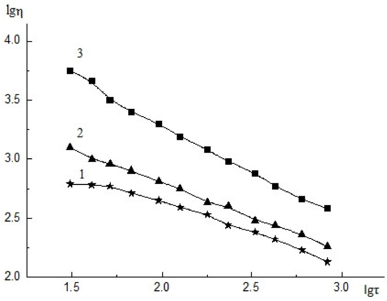
The amount of CNW used for modification of the ALG solution was selected experimentally and depended on the viscous properties of the composite solution and its structure. As shown earlier, insoluble CNW particles caused structurization of the CS solution and facilitate electrospinning [37]. The CNW introduced into the ALG solution promoted electrospinning while simultaneously acting as an active filler (due to electrostatic interactions with ALG). Introducing 2.5% CNW into the ALG solution led to an insignificant increase in the viscosity of the composite solution and in the degree of structurization of this solution (Figure 1(2)) compared with that of the initial ALG solution (Figure 1(1)). Increasing the CNW content in the ALG solution up to 7.5% resulted in an increase in the initial viscosity of the solution (Figure 1(3)) and the degree of structurization of the composite solution (due to interactions between the positively charged CNW amino groups and the negatively charged carboxyl groups of ALG). A further rise in the amount of CNW led to a dramatic increase in the solution viscosity and its degree of structurization, and the solutions were no longer suitable for electrospinning.
Figure 1.
Flow curves of 4% ALG solution (1), 4% ALG solution with 2.5% CNW, 4% ALG solution with 7.5% CNW, 20 °C, η–viscosity (mPa∙s−1), τ–shear stress (Pa). The relative standard deviation of the measurements did not exceed 5% (n = 3).
The electrospinning parameters described in Section 2.3 (voltage of 60–75 kV, distance between electrodes of 22–24 cm, and rotation speed of spinning electrode of 10–16 min−1) were experimentally selected for each solution to ensure spinning stability and uniformity of the material.
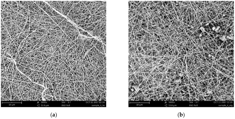
The SEM images of the CS–ALG&CNW bilayer scaffold (Figure 2) demonstrated a reasonably uniform fiber formation without any bead formation. The introduction of CNW had a beneficial effect and facilitated the formation of a more uniform material similar to that obtained with CS spinning. The average diameters of the fibers ranged from 360 to 420 nm for the CS side and from 200 to 300 nm for the ALG&CNW side. The distribution of the nanofiber thicknesses was narrower on the ALG&CNW side of the scaffold. Deposition of an ALG&CNW layer onto the CS layer led to the formation of a stable composite at the expense of the interaction between the polyelectrolyte layers.
Figure 2.
SEM images of the CS surface (a) and the ALG&CNW surface (b) of the bilayer CS–ALG&CNW scaffold.
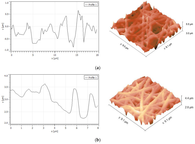
AFM analysis of the CS–ALG&CNW scaffold also revealed smooth beadless fibers (Figure 3) that had a continuous 3D network structure with interconnected pores similar to those of natural ECM. No significant differences were noted in the surface morphology of the two layers. The average fiber diameter determined from AFM images was 425 ± 58 nm for CS surface and 411 ± 67 nm for ALG&CNW surface. The differences in these results from the SEM measurements for ALG fibers may have been related to an overestimation of the lateral dimensions by the scanning probe, as well as the smaller number of measurements. The fiber network formed surface pores with diameters up to 2 μm and depths up to 1 μm. The rough scaffold surface interacted with the cells to provide numerous contacts.
Figure 3.
AFM morphology and roughness profiles of the CS surface (a) and the ALG&CNW surface (b) of the of the bilayer CS–ALG&CNW scaffold.
The roughness parameters are presented in Table 1. The average roughness was evaluated as 0.39 μm for CS and 0.27 μm for ALG&CNW surfaces. These roughness values were higher than those previously estimated for PCL/CS fibers with diameters of 250–400 nm [38]; the average roughness of the nanofibers increased with decreasing fiber diameter and with increases in the dominant alignment direction. However, for electrospun microfibers, the roughness ranged from 1.5–6.3 µm and was dependent on the processing conditions and fiber diameter, but independent of the polymer used [39]. Furthermore, the pore parameters and surface roughness were the main factors that influenced the contact angle and scaffold surface properties [40]. The roughness parameters estimated in this study were typical for electrospun matrices, and the cells responded well to scaffold roughnesses of 0.4–2 μm [41].
Table 1.
Roughness parameters of CS and ALG&CNW surfaces of the bilayer CS–ALG&CNW scaffold.
| Roughness Parameter | CS Surface | ALG&CNW Surface |
|---|---|---|
| Peak-to-peak roughness, µm | 6.13 | 4.76 |
| Average roughness, µm | 0.39 | 0.27 |
| Root mean square roughness, µm | 0.50 | 0.25 |
3.2. X-Ray Diffraction Structure
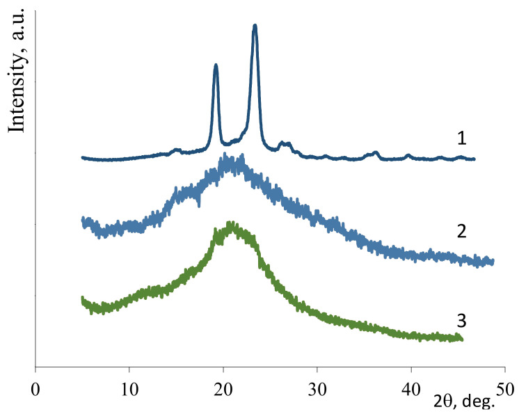
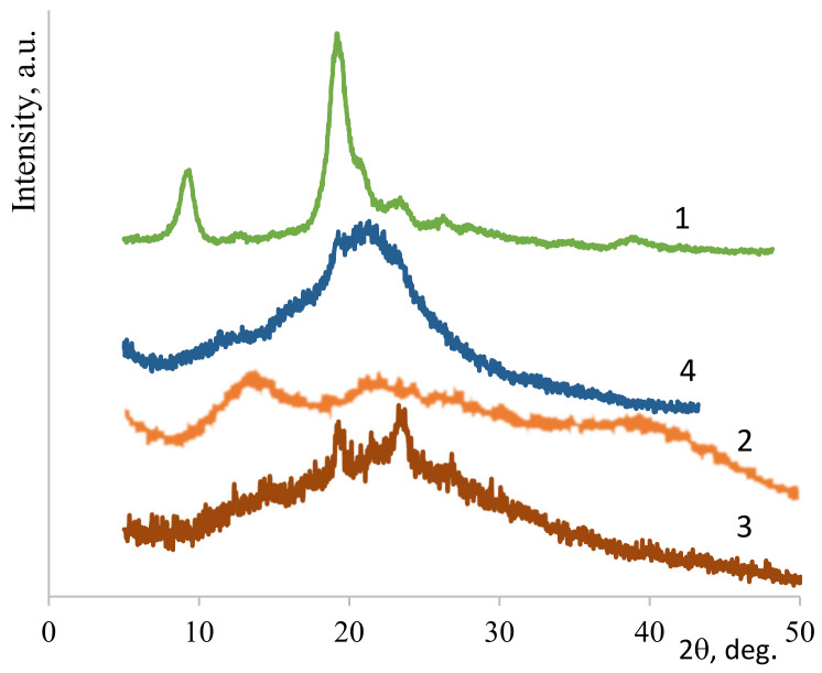
Efficient electrospinning of polysaccharides required the presence of PEO. The nonwoven PEO had a high degree of crystallinity (85%, see Figure 4(1)). As shown previously [13], comparative X-ray diffraction analysis of the polysaccharide films with and without PEO revealed that the interaction between polysaccharides and PEO became stronger during electrospinning. Thus, in the case of nonwoven CS (Figure 4(3)), the signal was more intense in the 2θ range of 19–24° than in the X-ray pattern of the CS film (Figure 4(2)). This finding supported the presence of PEO and an interaction between CS and PEO arising during electrospinning, as confirmed by the literature data [42]. The presence of PEO and CNW in the nonwoven ALG&CNW (Figure 5(3)) led to some changes in its structure when compared with that of the ALG film (Figure 5(2)). The X-ray diffraction pattern of the bilayer CS–ALG&CNW scaffold (Figure 5(4)) included a strong signal in the range 2θ = 19–24° and a shoulder in the range 2θ = 13–15°, which combined the diffraction patterns of CS (Figure 4(2)) and ALG&CNW (Figure 5(3)). This result indicated that strong intermolecular interactions arose during electrospinning and led to changes in the hydrophilicity of the bilayer scaffold, as evidenced by the absence of the reflex 2θ = 9.8° characteristic for α-chitin (Figure 5(1)).
Figure 4.
X-ray diffraction patterns: PEO-nonwoven (1), CS-film (2), CS–PEO-nonwoven (3).
Figure 5.
X-ray diffraction patterns: CNW (1), ALG-film (2), ALG&CNW-nonwoven (3), and CS–ALG&CNW-nonwoven (4).
3.3. Swelling
The bilayer CS–ALG&CNW scaffold consisted of a layer of CS and a layer of ALG&CNW. In addition, a water-insoluble polyelectrolyte complex (PEC) formed during contact of the oppositely charged polymers in the process of multilayer spinning. The swelling of the bilayer scaffold (Table 2) was determined from the properties of the initial polymers and the changes that occurred during electrospinning and subsequent processing. The strong intermolecular interactions between CS and PEO that arose during electrospinning caused a partial loss of solubility in water of nonwoven CS [42,43]. Subsequent heating of the nonwoven CS led to a solubility loss and a reduction in the degree of swelling in water and in physiological saline (Table 2); these changes were associated with the formation of amide crosslinks [44]. The nonwoven ALG&CNW was partially dissolved in water and contained microgels (Table 2) composed of the PEC that formed as a result of the interaction between the CNW amino groups and the ALG carboxyl groups [25]. Heating of the nonwoven CS-ALG&CNW (Table 2) led to a loss of solubility in water and physiological saline due to strengthening of the chemical interactions.
Table 2.
Swelling of nonwoven materials (mean ± SD, n = 3).
| Sample | Treatment | Swelling in Water, g/g | Swelling in 0.9% NaCl, g/g |
|---|---|---|---|
| CS | 80 °C, 4 h | 5.3 ± 0.3 | 2.2 ± 0.2 |
| ALG&CNW | - | partially dissolved | partially dissolved |
| CS-ALG&CNW | 80 °C, 4 h | 2.5 ± 0.2 | 2.0 ± 0.2 |
3.4. Porosity
The electrospun monolayer CS [13] and bilayer CS-ALG&CNW scaffolds had large inner surfaces (Table 3) and well-developed pore structures that could facilitate cell adhesion, migration, proliferation, and differentiation. The porosity was somewhat greater for the monolayer CS scaffold than for the bilayer CS-ALG&CNW. The pores were wider in the CS-ALG&CNW scaffold.
Table 3.
Porosity of the scaffolds.
| Parameter | CS [13] | CS-ALG&CNW |
|---|---|---|
| Average logarithmic pore radius (nm) | 1.62 | 2.26 |
| Average pore radius, nm | 489 | 2193 |
| Porosity over weight, cm3/g | 9.36 | 8.48 |
| Porosity over volume, cm3/cm3 | 0.976 | 0.861 |
| Meso- and macro-pore surface over weight, m2/g | 878 | 878 |
| Meso- and macro-pore surface over volume, m2/cm3 | 89.1 | 89.1 |
| Total pore surface over weight, m2/g | 2464 | 1463 |
| Total pore surface over volume, m2/cm3 | 257 | 149 |
3.5. Testing of Cell Adhesion Properties
The MMSCs visualized on the sample surfaces formed three groups that differed in their morphological characteristics: adhered cells (isolated, multiple), colonies formed by these cells (monolayer, spheroids), and conditionally non-adhered cells (isolated, multiple) that had presumably undergone apoptosis (Table 4).
Table 4.
Characteristics of multipotent mesenchymal stem cells (MMSCs) and cell colonies formed on different scaffolds at 3 days after seeding.
| Sample | Non-Adhered Cells | Adhered Cells | Prevailing Type of Colony | The Average Size of MMSC Spheroids, µm (mean ± SD) |
|---|---|---|---|---|
| Glass (control) | - | multiple | monolayer | |
| CS | isolated | multiple | spheroids | 70±37 |
| CS-ALG&CNW | isolated | multiple | monolayer + spheroids | 109±43* |
* Reliability of changes in comparison with the control group (Mann−Whitney): * p < 0.05.
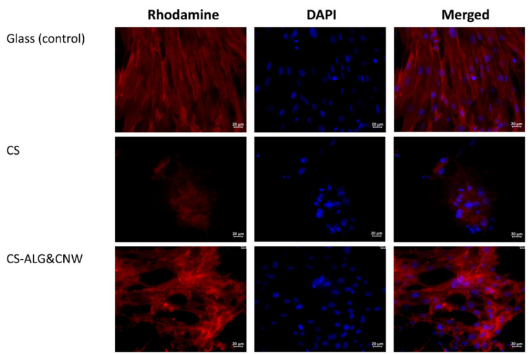
The cells grown on cover glasses (the control group) were spread on the glass surface and formed a confluent/subconfluent monolayer. They had the typical elongated cell shape with multiple pseudopodia. Many cells were in the process of division (Figure 6). Cells on the CS control sample were located on the surface as individual isolated cells or they formed two-dimensional structures and spheroid colonies of different sizes. The isolated cells had circular shapes. The cells located at the periphery of the large spheroids had a spindle-like shape and gave way to small flat colonies (Table 4, Figure 6 and Figure 7).
Figure 6.
Multipotent mesenchymal stem cells (MMSCs) adhered onto the surfaces of cover glasses and scaffolds. Vinculin in the cell cytoskeletons was stained with a fluorochrome (rhodamine channel); cell nuclei were stained with 4′,6-diamidino-2-phenylindole (DAPI). Combined two-channel image. Magnification ×40.
Figure 7.
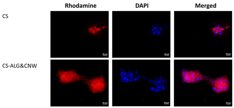
Multipotent mesenchymal stem cell spheroids on sample surfaces. Vinculin in the cell cytoskeletons was stained with a fluorochrome (rhodamine channel); cell nuclei were stained with 4′,6-diamidino-2-phenylindole (DAPI). Combined two-channel image. Magnification ×40.
The cells on the CS-ALG&CNW scaffold were located on the surface in the form of a monolayer (confluence 70–100%) with predominantly flat colonies and large numbers of spheroids. Cells in the flat colonies had a typical elongated shape with multiple pseudopodia. Isolated cells had circular shapes with small peripheral protrusions. The cells located at the periphery of the spheroids had a spindle-like shape and few pseudopodia. Several spheroidal colonies were connected via “bridges” of cells migrating from the spheroids (Table 4, Figure 6 and Figure 7).
Cultivation of MMSCs on the surfaces of scaffolds based on CS and its composites were characterized by an organization of colonies in the shape of multicellular spheroidal aggregates [13,45]. The formation of spheroids on the surface of CS scaffolds included several stages. The first stage consisted of adhesion and spreading of the cells on the scaffold surface, with formation of multiple pseudopodia. The pseudopodia were then retracted and the cells acquired circular shapes and formed three-dimensional spheroidal colonies [46,47]. Under favorable conditions, the cells located on the periphery acquired spindle-like shapes and migrated onto the adhesive surface of the material via the formation of cellular “bridges” (which interconnected the spheroids with each other). Alternatively, they formed isolated two-dimensional colonies (monolayers with various degrees of confluence). No MMSC migration occurred from the spheroids on non-adhesive polymer surfaces [13,48].
The sizes of the spheroids and the degree of confluence of the monolayer consisting of migrating cells were determined by the mobility of the cells in the spheroid aggregates. Cells with high mobility produced larger spheroids more quickly, and they formed two-dimensional colonies with larger areas. An increase in spheroid size was also possible at the expense of merging (for example, on a CS-HA surface). No merging of spheroids was observed on CS scaffolds [46]. Cell mobility depended on the MMSC source and on the adhesive characteristics of the polymer surface, which were determined by the composition of the material. The spheroids formed on CS-HA scaffolds were also larger than those formed on CS [46].
The MMSCs found in spheroids possessed a greater capacity for differentiation. They also showed more pronounced anti-inflammation, regenerative, and reparative properties than those formed in two-dimensional culture [45,48,49]. These features of MMSCs formed in three-dimensional colonies could be explained by the increased expression of genes associated with hypoxia, angiogenesis, inflammation, stress responses, and redox signaling [45].
4. Conclusions
The method of scaffold preparation by electrospinning generated fine fiber structures of high porosity and low density that closely mimicked the nature of the ECM and created a good microenvironment for growth of cells and tissues. Polysaccharides (CS, ALG, chitin) were used to develop bilayer electrospun CS–ALG&CNW membranes with average fiber diameters of 200–400 nm and high porosity. ALG electrospinning benefited from the addition of CNW, which provided structuring for the ALG solution. The result was the production of beadless fibers that were able to maintain their structure under high swelling conditions. The pore size of the ALG fibers was larger than that of a CS layer electrospun under the same conditions. Thus, the chemical composition, as well as the layer structure, was favorable for cell growth.
In vitro testing of the monolayer CS scaffold and the bilayer CS–ALG&CNW scaffold revealed spheroidal MMSC colonies on the surfaces of both types of samples. Indirect signs of cell migration from the spheroids (spindle-like cells with pseudopodia on the periphery of the spheroids) were observed on the surfaces of both samples. Some of the spheroids on the CS–ALG&CNW scaffold were connected to each other via “bridges” of migrating cells. These cell “bridges” that formed between the spheroids on the CS–ALG&CNW scaffold were flat monolayer cultures with a confluence reaching 100% in some areas. The wide surface area of these flat colonies was possibly a result of their primary formation from a portion of adhered cells, rather than from migration and proliferation of cells from the spheroids. The obtained data indicate that the deposition of an outer ALG layer modified with 7.5% CNW onto the surface of a CS-based composite material improved the adhesive characteristics of the scaffold. This could indicate an increased biocompatibility of the CNW-modified scaffolds.
Acknowledgments
The authors would like to thank INMED LLC (CEO A.V. Vnuchkin) for providing the electrospinning equipment, N.M. Zabivalova (INMED LLC) for obtaining the SEM images, and the Research Park of St. Petersburg State University (Thermogravimetric and Calorimetric Research Centre) for the porosity measurements.
Author Contributions
Conceptualization, V.A.P. and Y.A.S.; methodology, V.A.P. and A.S.G.; investigation, V.A.P., A.S.G., A.I.M., D.P.R., D.D.C., and D.N.P.; writing—original draft preparation, V.A.P., A.S.G., D.N.P., and Y.A.S.; writing—review and editing, Y.A.S. and A.S.G.; supervision, Y.A.S.; project administration, Y.A.S.; funding acquisition, Y.A.S. All authors have read and agreed to the published version of the manuscript.
Funding
This research was funded by the Russian Foundation for Basic Research, project 18-29-17074.
Conflicts of Interest
The authors declare no conflict of interest. The funders had no role in the design of the study; in the collection, analyses, or interpretation of data; in the writing of the manuscript, or in the decision to publish the results.
References
- 1.Al-Enizi A.M., Zagho M.M., Elzatahry A.A. Polymer-based electrospun nanofibers for biomedical applications. Nanomaterials. 2018;8:259. doi: 10.3390/nano8040259. [DOI] [PMC free article] [PubMed] [Google Scholar]
- 2.Naeimirad M., Zadhoush A., Kotek R., Neisiany R.E., Khorasani S.N., Ramakrishna S. Recent advances in core/shell bicomponent fibers and nanofibers: A review. J. Appl. Polym. Sci. 2018;135:46265. doi: 10.1002/app.46265. [DOI] [Google Scholar]
- 3.Norouzi M. Recent advances in brain tumor therapy: Application of electrospun nanofibers. Drug Discov. Today. 2018;23:912–919. doi: 10.1016/j.drudis.2018.02.007. [DOI] [PubMed] [Google Scholar]
- 4.Jun I., Han H.-S., Edwards J.R., Jeon H. Electrospun Fibrous Scaffolds for Tissue Engineering: Viewpoints on Architecture and Fabrication. Int. J. Mol. Sci. 2018;19:745. doi: 10.3390/ijms19030745. [DOI] [PMC free article] [PubMed] [Google Scholar]
- 5.Paim Á., Tessaro I.C., Cardozo N.S.M., Pranke P. Mesenchymal stem cell cultivation in electrospun scaffolds: Mechanistic modeling for tissue engineering. J. Biol. Phys. 2018;44:245–271. doi: 10.1007/s10867-018-9482-y. [DOI] [PMC free article] [PubMed] [Google Scholar]
- 6.Steffens D., Braghirolli D.I., Maurmann N., Pranke P. Update on the main use of biomaterials and techniques associated with tissue engineering. Drug Discov. Today. 2018;23:1474–1488. doi: 10.1016/j.drudis.2018.03.013. [DOI] [PubMed] [Google Scholar]
- 7.Agarwal S., Wendorff J.H., Greiner A. Use of electrospinning technique for biomedical applications. Polymer. 2008;49:5603–5621. doi: 10.1016/j.polymer.2008.09.014. [DOI] [Google Scholar]
- 8.Lee K.Y., Jeong L., Kang Y.O., Lee S.J., Park W.H. Electrospinning of polysaccharides for regenerative medicine. Adv. Drug Deliv. Rev. 2009;61:1020–1032. doi: 10.1016/j.addr.2009.07.006. [DOI] [PubMed] [Google Scholar]
- 9.Garg T., Rath G., Goyal A.K. Biomaterials-based nanofiber scaffold: Targeted and controlled carrier for cell and drug delivery. J. Drug Target. 2015;23:202–221. doi: 10.3109/1061186X.2014.992899. [DOI] [PubMed] [Google Scholar]
- 10.Saquing C.D., Tang C., Monian B., Bonino C.A., Manasco J.L., Alsberg E., Khan S.A. Alginate–Polyethylene Oxide Blend Nanofibers and the Role of the Carrier Polymer in Electrospinning. Ind. Eng. Chem. Res. 2013;52:8692–8704. doi: 10.1021/ie302385b. [DOI] [Google Scholar]
- 11.Naseri N., Mathew A.P., Oksman K. Electrospinnability of bionanocomposites with high nanocrystal loadings: The effect of nanocrystal surface characteristics. Carbohydr. Polym. 2016;147:464–472. doi: 10.1016/j.carbpol.2016.04.018. [DOI] [PubMed] [Google Scholar]
- 12.Gizaw M., Thompson J., Faglie A., Lee S.-Y., Neuenschwander P., Chou S.-F. Electrospun fibers as a dressing material for drug and biological agent delivery in wound healing applications. Bioengineering. 2018;5:9. doi: 10.3390/bioengineering5010009. [DOI] [PMC free article] [PubMed] [Google Scholar]
- 13.Petrova V.A., Chernyakov D.D., Poshina D.N., Gofman I.V., Romanov D.P., Mishanin A.I., Golovkin A.S., Skorik Y.A. Electrospun bilayer chitosan/hyaluronan material and its compatibility with mesenchymal stem cells. Materials. 2019;12:2016. doi: 10.3390/ma12122016. [DOI] [PMC free article] [PubMed] [Google Scholar]
- 14.Ifuku S. Chitin and chitosan nanofibers: Preparation and chemical modifications. Molecules. 2014;19:18367–18380. doi: 10.3390/molecules191118367. [DOI] [PMC free article] [PubMed] [Google Scholar]
- 15.Tamura H., Furuike T., Nair S., Jayakumar R. Biomedical applications of chitin hydrogel membranes and scaffolds. Carbohydr. Polym. 2011;84:820–824. doi: 10.1016/j.carbpol.2010.06.001. [DOI] [Google Scholar]
- 16.Rinaudo M. Chitin and chitosan: Properties and applications. Prog. Polym. Sci. 2006;31:603–632. doi: 10.1016/j.progpolymsci.2006.06.001. [DOI] [Google Scholar]
- 17.Muzzarelli R.A. Biomedical Exploitation of Chitin and Chitosan via Mechano-Chemical Disassembly, Electrospinning, Dissolution in Imidazolium Ionic Liquids, and Supercritical Drying. Mar. Drugs. 2011;9:1510–1533. doi: 10.3390/md9091510. [DOI] [PMC free article] [PubMed] [Google Scholar]
- 18.Anitha A., Sowmya S., Jayakumar R., Deepthi S., Chennazhi K., Ehrlich H., Tsurkan M.V., Jayakumar R. Chitin and chitosan in selected biomedical applications. Prog. Polym. Sci. 2014;39:1644–1667. doi: 10.1016/j.progpolymsci.2014.02.008. [DOI] [Google Scholar]
- 19.Mincea M., Negrulescu A., Ostafe V. Preparation, modification, and applications of chitin nanowhiskers: A review. Rev. Adv. Mater. Sci. 2012;30:225–242. [Google Scholar]
- 20.Jayakumar R., Prabaharan M., Kumar P.S., Nair S., Tamura H. Biomaterials based on chitin and chitosan in wound dressing applications. Biotechnol. Adv. 2011;29:322–337. doi: 10.1016/j.biotechadv.2011.01.005. [DOI] [PubMed] [Google Scholar]
- 21.Heath L., Zhu L., Thielemans W. Chitin nanowhisker aerogels. ChemSusChem. 2013;6:537–544. doi: 10.1002/cssc.201200717. [DOI] [PMC free article] [PubMed] [Google Scholar]
- 22.Naseri N., Algan C., Jacobs V., John M., Oksman K., Mathew A.P. Electrospun chitosan-based nanocomposite mats reinforced with chitin nanocrystals for wound dressing. Carbohydr. Polym. 2014;109:7–15. doi: 10.1016/j.carbpol.2014.03.031. [DOI] [PubMed] [Google Scholar]
- 23.Ou X., Zheng J., Zhao X., Liu M. Chemically Cross-Linked Chitin Nanocrystal Scaffolds for Drug Delivery. ACS Appl. Nano Mater. 2018;1:6790–6799. doi: 10.1021/acsanm.8b01585. [DOI] [Google Scholar]
- 24.Pangon A., Saesoo S., Saengkrit N., Ruktanonchai U.R., Intasanta V. Hydroxyapatite-hybridized chitosan/chitin whisker bionanocomposite fibers for bone tissue engineering applications. Carbohydr. Polym. 2016;144:419–427. doi: 10.1016/j.carbpol.2016.02.053. [DOI] [PubMed] [Google Scholar]
- 25.Petrova V.A., Elokhovskiy V.Y., Raik S.V., Poshina D.N., Romanov D.P., Skorik Y.A. Alginate gel reinforcement with chitin nanowhiskers modulates rheological properties and drug release profile. Biomolecules. 2019;9:291. doi: 10.3390/biom9070291. [DOI] [PMC free article] [PubMed] [Google Scholar]
- 26.Kiroshka V.V., Petrova V.A., Chernyakov D.D., Bozhkova Y.O., Kiroshka K.V., Baklagina Y.G., Romanov D.P., Kremnev R.V., Skorik Y.A. Influence of chitosan-chitin nanofiber composites on cytoskeleton structure and the proliferation of rat bone marrow stromal cells. J. Mater. Sci. Mater. Electron. 2016;28:21. doi: 10.1007/s10856-016-5822-2. [DOI] [PubMed] [Google Scholar]
- 27.Jayakumar R., Prabaharan M., Nair S., Tamura H. Novel chitin and chitosan nanofibers in biomedical applications. Biotechnol. Adv. 2010;28:142–150. doi: 10.1016/j.biotechadv.2009.11.001. [DOI] [PubMed] [Google Scholar]
- 28.Rejinold N.S., Nair A., Sabitha M., Chennazhi K.P., Tamura H., Nair S., Jayakumar R. Synthesis, characterization and in vitro cytocompatibility studies of chitin nanogels for biomedical applications. Carbohydr. Polym. 2012;87:943–949. doi: 10.1016/j.carbpol.2011.08.044. [DOI] [PubMed] [Google Scholar]
- 29.Williams D.F. There is no such thing as a biocompatible material. Biomaterials. 2014;35:10009–10014. doi: 10.1016/j.biomaterials.2014.08.035. [DOI] [PubMed] [Google Scholar]
- 30.Sharifpanah F., Reinhardt M., Schonleben J., Meyer C., Richter M., Schnabelrauch M., Rode C., Wartenberg A., Bekhite M., Sauer H., et al. Embryonic stem cells for tissue biocompatibility, angiogenesis, and inflammation testing. Cells Tissues Organs. 2017;204:1–12. doi: 10.1159/000471794. [DOI] [PubMed] [Google Scholar]
- 31.Hussein K.H., Park K.-M., Kang K.-S., Woo H.-M. Biocompatibility evaluation of tissue-engineered decellularized scaffolds for biomedical application. Mater. Sci. Eng. C. 2016;67:766–778. doi: 10.1016/j.msec.2016.05.068. [DOI] [PubMed] [Google Scholar]
- 32.Yan J., Yang L., Wang G., Xiao Y., Zhang B., Qi N. Biocompatibility Evaluation of Chitosan-based Injectable Hydrogels for the Culturing Mice Mesenchymal Stem Cells In Vitro. J. Biomater. Appl. 2009;24:625–637. doi: 10.1177/0885328208100536. [DOI] [PubMed] [Google Scholar]
- 33.Heo S.-J., Driscoll T.P., Thorpe S.D., Nerurkar N.L., Baker B.M., Yang M.T., Chen C.S., Lee D.A., Mauck R.L. Differentiation alters stem cell nuclear architecture, mechanics, and mechano-sensitivity. eLife. 2016;5:283. doi: 10.7554/eLife.18207. [DOI] [PMC free article] [PubMed] [Google Scholar]
- 34.Bolbasov E., Goreninskii S., Tverdokhlebov S., Mishanin A., Viknianshchuk A., Bezuidenhout D., Golovkin A. Comparative Study of the Physical, Topographical and Biological Properties of Electrospinning PCL, PLLA, their Blend and Copolymer Scaffolds. IOP Conf. Series Mater. Sci. Eng. 2018;350:012012. doi: 10.1088/1757-899X/350/1/012012. [DOI] [Google Scholar]
- 35.Fan Y., Saito T., Isogai A. Individual chitin nano-whiskers prepared from partially deacetylated α-chitin by fibril surface cationization. Carbohydr. Polym. 2010;79:1046–1051. doi: 10.1016/j.carbpol.2009.10.044. [DOI] [Google Scholar]
- 36.Petrova V.A., Panevin A., Zhuravskii S.G., Gasilova E.R., Vlasova E.N., Romanov D.P., Poshina D.N., Skorik Y.A. Preparation of N-succinyl-chitin nanoparticles and their applications in otoneurological pathology. Int. J. Biol. Macromol. 2018;120:1023–1029. doi: 10.1016/j.ijbiomac.2018.08.180. [DOI] [PubMed] [Google Scholar]
- 37.Dobrovolskaya I.P., Yudin V.E., Popryadukhin P.V., Ivan’Kova E.M., Shabunin A.S., Kasatkin I., Morgantie P. Effect of chitin nanofibrils on electrospinning of chitosan-based composite nanofibers. Carbohydr. Polym. 2018;194:260–266. doi: 10.1016/j.carbpol.2018.03.074. [DOI] [PubMed] [Google Scholar]
- 38.Semnani D., Naghashzargar E., Hadjianfar M., Manshadi F.D., Mohammadi S., Karbasi S., Effaty F. Evaluation of PCL/Chitosan Electrospun Nanofibers for Liver Tissue Engineering. Int. J. Polym. Mater. 2016;66:149–157. doi: 10.1080/00914037.2016.1190931. [DOI] [Google Scholar]
- 39.Milleret V., Hefti T., Hall H., Vogel V., Eberli D. Influence of the fiber diameter and surface roughness of electrospun vascular grafts on blood activation. Acta Biomater. 2012;8:4349–4356. doi: 10.1016/j.actbio.2012.07.032. [DOI] [PubMed] [Google Scholar]
- 40.Cho D., Chen S., Jeong Y., Joo Y.L. Surface hydro-properties of electrospun fiber mats. Fibers Polym. 2015;16:1578–1586. doi: 10.1007/s12221-015-5258-1. [DOI] [Google Scholar]
- 41.Denchai A., Tartarini D., Mele E. Cellular Response to Surface Morphology: Electrospinning and Computational Modeling. Front. Bioeng. Biotechnol. 2018;6:155. doi: 10.3389/fbioe.2018.00155. [DOI] [PMC free article] [PubMed] [Google Scholar]
- 42.Sashina E.S., Vnuchkin A.V., Novoselov N.P. A study of the thermodynamics of chitosan interaction with polyvinyl alcohol and polyethylene oxide by differential scanning calorimetry. Russ. J. Appl. Chem. 2006;79:1643–1646. doi: 10.1134/S107042720610017X. [DOI] [Google Scholar]
- 43.Pakravan M., Heuzey M.-C., Ajji A. A fundamental study of chitosan/peo electrospinning. Polymer. 2011;52:4813–4824. doi: 10.1016/j.polymer.2011.08.034. [DOI] [Google Scholar]
- 44.Zotkin M.A., Vikhoreva G.A., Kechek’yan A.S. Thermal modification of chitosan films in the form of salts with various acids. Polym. Sci. Ser. B. 2004;46:39–42. [Google Scholar]
- 45.Cesarz Z., Tamama K. Spheroid Culture of Mesenchymal Stem Cells. Stem Cells Int. 2016;2016:9176357. doi: 10.1155/2016/9176357. [DOI] [PMC free article] [PubMed] [Google Scholar]
- 46.Huang G.S., Dai L.G., Yen B.L., Hsu S.H. Spheroid formation of mesenchymal stem cells on chitosan and chitosan-hyaluronan membranes. Biomaterials. 2011;32:6929–6945. doi: 10.1016/j.biomaterials.2011.05.092. [DOI] [PubMed] [Google Scholar]
- 47.Yeh H.Y., Liu B.H., Sieber M., Hsu S.H. Substrate-dependent gene regulation of self-assembled human msc spheroids on chitosan membranes. BMC Genom. 2014;15:10. doi: 10.1186/1471-2164-15-10. [DOI] [PMC free article] [PubMed] [Google Scholar]
- 48.Bartosh T.J., Ylostalo J.H., Mohammadipoor A., Bazhanov N., Coble K., Claypool K., Lee R.H., Choi H., Prockop D.J. Aggregation of human mesenchymal stromal cells (mscs) into 3d spheroids enhances their antiinflammatory properties. Proc. Natl. Acad. Sci. USA. 2010;107:13724–13729. doi: 10.1073/pnas.1008117107. [DOI] [PMC free article] [PubMed] [Google Scholar]
- 49.Okumura K., Nakamura K., Hisatomi Y., Nagano K., Tanaka Y., Terada K., Sugiyama T., Umeyama K., Matsumoto K., Yamamoto T., et al. Salivary gland progenitor cells induced by duct ligation differentiate into hepatic and pancreatic lineages. Hepatology. 2003;38:104–113. doi: 10.1053/jhep.2003.50259. [DOI] [PubMed] [Google Scholar]


