

Abstract

We find, through atomistic molecular dynamics simulation of native cyclodextrins (CDs) in water, that although the outer surface of a CD appears like a truncated cone, the inner cavity resembles a conical hourglass because of the inward protrusion of the glycosidic oxygens. Furthermore, the conformations of the constituent α-glucose molecules are found to differ significantly from a free monomeric α-glucose molecule. This is the first computational study that maps the conformational change to the preferential hydrogen bond donating capacity of one of the secondary hydroxyl groups of CD, in consensus with an NMR experiment. We have developed a simple and novel geometry-based technique to identify water molecules occupying the nonspherical CD cavity, and the computed water occupancies are in close agreement with the experimental and density functional theory studies. Our analysis reveals that a water molecule in CD cavity loses out about two hydrogen bonds and remains energetically frustrated but possesses higher orientational degree of freedom compared to bulk water. In the context of CD-drug complexation, these imply a nonclassical, that is, enthalpically driven hydrophobic association of a drug in CD cavity.
Introduction
Cyclodextrins (CDs) as the name suggests are cyclic carbohydrates, comprising α-glucose molecules connected by 1–4 linkage, obtained from enzymatic degradation of starch using glycosyl transferases.1,2 The native abundant forms of CDs are α-CD, β-CD, and γ-CD consisting of 6, 7, and 8 glucose molecules in the ring; α- and γ-CD are highly soluble in water, however, the solubility of β-CD is ten-fold lower than the others.2−4 The circular arrangement of α-glucose with primary hydroxyl groups located on one rim and the secondary hydroxyl groups on the other rim results in a hollow truncated cone structure. The prevalence of dynamical flip-flop hydrogen bonds in the secondary hydroxyl rim (O2–H2···H3–O3) of β-CD imparts structural rigidity and is ascribed for its low solubility.5 The central cavity with a diameter of 4–8 Å,2−4 being hydrophobic compared to the either rims, can comfortably encapsulate small hydrophobic solutes.
The formation of inclusion complexes by CD has led to its diverse application in food,6−9 cosmetic,10−12 environmental,13−15 agriculture,16 textile,17 chemical, and biotech industries.2,4,18 For example, CD helps in separating cholesterol from milk9 and in removing odor from air15 by trapping the causative organic compound. The biocompatibility, biodegradability, and low immunogenicity of CD make it a very promising drug carrier.19−22 Complexing sparingly soluble hydrophobic drug with CD improves the bioavailability of the drug and enables a sustained and controlled drug release. Some CD-based drugs with trade names viz., Aerodiol, Omebeta, Lonmiel, and Mitozytrex are already available in the market.19 Further research on the development of efficient CD-based nano-carriers, especially for anticancer drugs, is extensively pursued.20−22 The low production cost and the efficient drug complexation because of its perfect cavity size and stable rigid structure make β-CD a preferred drug carrier; its major drawback of low solubility can be surpassed by substituting some of the secondary hydroxyl groups by methyl (M-β-CD) or hydroxypropyl (HP-β-CD) or sulfobutyl ether (SBE-β-CD) groups; ∼25–30 fold enhancement of solubility has been reported.21
The major driving forces for CD inclusion complex have been suggested to be van der Waals interaction and hydrophobic interaction.3,23,24 The electrostatic and hydrogen bonding, although not dominant, could significantly influence the conformation of the complex. As per the classical view, a hydrophobic association is entropically driven as the ordered water around the solute gains entropy upon relocating to the bulk medium.25 Contrastingly, the experimental evidence of both the enthalpy and the entropy change to be negative during complexation imply a nonclassical, i.e., enthalpically driven association of an apolar guest into the host CD cavity.3
In aqueous solution, in the absence of a guest molecule, the CD cavity is typically filled by water molecules, corroborated by the X-ray and neutron diffraction studies.1,4,5,26−31 An average occupancy of 2.6,27 6.5,28 and 8.831 waters, statistically distributed over multiple sites inside the cavity of α-CD, β-CD, and γ-CD, respectively, has been reported. Such waters confined within the cavity may not be able to complete its hydrogen bond network as in bulk medium and, hence, would be energetically frustrated.3,23 Liberation of these high-energy water from the cavity, as a ligand enters into the cavity, makes the cavity–ligand complexation an enthalpically driven process.32,33 Indeed, the release of the high-energy waters from the cavity has been confirmed through isothermal titration calorimetry and molecular dynamics (MD) simulations, as an essential driving force for high affinity binding of neutral guest molecules with cucurbit[n]urils.34 Moreover, larger the deficiency of the hydrogen bonds for the cavity waters, higher is the affinity of the supramolecular complex,33 but not a strong correlation as other factors like host–guest interaction and host–water hydrogen bonds could also influence the stability of the inclusion complex. Unlike cucurbit[n]urils, glycosidic oxygen and hydroxyl groups of the CD can form hydrogen bond with cavity waters. A detailed understanding of hydration of CD, especially inside the cavity, is imperative for a comprehensive understanding of CD-drug interactions.
Numerous MD simulation studies have investigated the conformational dynamics and hydration of native and substituted CDs using various force fields like CVFF,35 CSFF/CHARMM,36−40 GROMOS,41−44 GLYCAM98,45 q4mdCD,46 and OPLS.47,48 The accuracy of the MD results, indeed, depends on the reliability of the underlying molecular model. Development of force field for carbohydrates had been a challenge to the computational chemists, compared to protein, lipids, or other biomolecules, owing to the conformational heterogeneity of carbohydrates.49,50 A comparative study on the newer carbohydrate force fields reports equivalent performance of 53A6GLYC, 56A6Carbo_R, 2016H66, CHARMM36, and amber-based q4mdCD force fields in reproducing the structural details of CD,51 closely agreeing with the crystallographic data. Only in these force fields, α-glucose of CD was predominantly found to adopt 4C1 chair conformation, however, a frequent tumbling (upside down orientation) of a few glucose units was observed for CHARMM36 and q4mdCD force fields, with lesser tumbling events for 56A6Carbo_R and 2016H66 force fields and none for 53A6GLYC. The hydrogen bond donating capacity of two secondary hydroxyl oxygens (O3 and O2) has been found to vary among the force fields—both are equivalent in CHARMM36; O2 to be a slightly better donor than O3 in q4mdCD; O3 to be a stronger donor (3–5 fold) than O2 for the GROMOS force fields. In this work, we have identified that the trend represented by the GROMOS force field is in compliance with a NMR spectroscopic measurement52 and is mainly due to the change in the conformation of the former hydroxyl group (O3H3) to avoid steric clashes upon cyclization.
From the spatial distribution of water around CD, the ordering of water around β-CD was observed to be higher than that around α-CD or γ-CD, by the virtue of the highly restrained motion of the β macrocyclic ring.37 Such an enhancement of the local water structure has been attributed for the low solubility of β-CD. Surprisingly, the hydration free energy, as estimated by free-energy perturbation, could not explain the anomalous solubility of β-CD, and indeed, the hydration free energy has been found to decrease with increase in the number of glucose units in the macrocycle.36 On the other hand, it has been reported in another MD study that the tetrahedral ordering of water gets disrupted in the vicinity of a CD molecule, with a profound effect on cavity confined waters, and to somewhat lesser extent on the outer hydration layer.43 Furthermore, the dynamics of water proximal to CD is also retarded—the relaxation time (τ) corresponding to translational diffusion, rotational motion, and hydrogen bond formation of waters in three regimes viz., intra cavity (c), hydration layer (h), and bulk(b) medium is determined to follow the order: τc > τh > τb.44 In the study, water in the hydration layer has been identified from the radial distribution function (rdf) of water around the oxygen atoms of the CD, while that in cavity has been identified by a grid-based approach.
Most of the simulation studies35,43,45,46 assume CD cavity to be spherical and report the coordination number, obtained from the area under the first peak of the rdf of water about the CD geometric center (center of mass), as the water occupancy inside cavity. The molecular structure of a CD is highly nonspherical; we find in our simulations, because of the inward protrusion of the glycosidic oxygen, the CD cavity to be narrower in the middle compared to the either outer hydroxyl rims. The heights of the hydroxyl rims from the CD center are also different. It is, therefore, fundamentally inappropriate to use rdf that assumes spherical symmetry for a molecule to compute water occupancy inside CD cavity. Some MD simulations have used cylindrical distribution function39,40 and grid-based approach.42,44 Although these are better techniques compared to spherical rdf, they assume an average CD structure and may not incorporate the conformational variation of CD in solution.
For an accurate estimation of water occupancy in CD cavity, here, we have developed a simple and novel geometry-based approach, incorporating the structural fluctuations of CD; the computed average and maximal water occupancies closely match with the crystallography1,4,5,26,28 and density functional theory (DFT) studies,53,54 respectively. We find the intra cavity waters to form less number of hydrogen bonds than bulk water; moreover, they preferably form hydrogen bond among themselves, forming only a few hydrogen bonds with the CD wall. The mean binding energy and the excess chemical potential of a water inside the cavity, although attractive, are found to be less favorable compared to bulk water as a result of its inability to complete its hydrogen bond network. The observed higher binding energy and lower tetrahedral ordering of the cavity confined water than that of bulk water hint that the expulsion of water from CD cavity to bulk medium, during CD-drug complexation, would be energetically driven.
Results and Discussion
CD Cavity Resembles a Conical Hourglass because of the Inward Protrusion of the Glycosidic Oxygens
Table 1 lists some structural parameters characterizing the molecular arrangement of the neighboring α-glucose units, the values obtained from our simulations are in close agreement with the values reported by crystallography4 and other simulation35,51 studies. The glycosidic dihedral angles ϕ and ψ of three native CDs are the same within the observed variation and correspond to the minima value of the 56A6Carbo_R force field;50 this imparts rigidity to the glycosidic rim as evident from the high circularity value of ∼0.9. The angle between three neighboring glycosidic oxygens (O1), δ, matches with the crystallographic data,4 furthermore, they are almost equal to the angle between the sides of a regular hexagon (120°) in α-CD, regular heptagon (128.5°) in β-CD, and regular octagon (135°) in γ-CD, clearly indicating an ideal polygonal arrangement of α-glucose units in the CD ring. Every glucose molecule adopted 4C1 conformation, and no flipping of the neighboring glucose units was observed during simulation. The cavity height, computed from the distance between the centers of mass of the primary and the secondary hydroxyl rims, is 0.55 nm for all native CDs, whereas a value of ∼0.8 nm reported by the diffraction studies4,35,46 could possibly correspond to a maximum distance between the hydrogens of the either hydroxyl rims; because of significant fluctuations in the hydrogen orientations, we did not include the positions of the hydrogen in measuring CD height. It is important to note that the outer hydroxyl rims are not equidistant from the CD center—the secondary hydroxyl rim is closer to the center than the primary hydroxyl rim (h12 < h16).
Table 1. Structural Parameters Describing Molecular Arrangement of Neighboring α-Glucose Units in Native CDsa.
| α-CD | β-CD | γ-CD | ||||
| parameter | this work | reported | this work | reported | this work | reported |
| ϕ, deg | 119.0 ± 4.2 | 117.2a | 117.0 ± 4.1 | 110.4a | 116.3 ± 3.4 | 115.6a |
| ψ, deg | 116.5 ± 3.3 | 116.0a | 116.4 ± 3.5 | 119.0a | 116.8 ± 2.6 | 116.5a |
| δ, deg | 119.7 ± 0.3 | 119.6a | 128.1 ± 0.4 | 127.4a | 134.4 ± 0.4 | 131.4a |
| 119.9c | 128.3c | 134.9c | ||||
| d11, nm | 0.42 ± 0.02 | 0.42a | 0.43 ± 0.02 | 0.43a | 0.44 ± 0.02 | 0.44a |
| 0.42c | 0.44c | 0.45c | ||||
| d23, nm | 0.29 ± 0.03 | 0.30a | 0.29 ± 0.03 | 0.34a | 0.29 ± 0.03 | 0.30a |
| 0.30c | 0.29c | 0.28c | ||||
| d66, nm | 0.55 ± 0.10 | 0.55a | 0.53 ± 0.10 | 0.55a | 0.52 ± 0.10 | 0.53a |
| rO1, nm | 0.42 ± 0.01 | 0.44 ± 0.06b | 0.49 ± 0.01 | 0.5 ± 0.07b | 0.58 ± 0.01 | 0.59 ± 0.08b |
| rO2, nm | 0.56 ± 0.01 | 0.64 ± 0.02 | 0.72 ± 0.01 | |||
| rO6, nm | 0.53 ± 0.04 | 0.59 ± 0.04 | 0.64 ± 0.04 | |||
| h12, nm | 0.24 ± 0.01 | 0.24 ± 0.01 | 0.24 ± 0.01 | |||
| h16, nm | 0.31 ± 0.02 | 0.31 ± 0.02 | 0.31 ± 0.02 | |||
| h, nm | 0.55 ± 0.03 | 0.55 ± 0.03 | 0.55 ± 0.03 | |||
| ΩO1 | 0.91 ± 0.03 | 0.89a | 0.89 ± 0.03 | 0.85a | 0.89 ± 0.03 | 0.89a |
| ΩO2 | 0.88 ± 0.04 | 0.87 ± 0.06 | 0.87 ± 0.04 | |||
| ΩO6 | 0.64 ± 0.08 | 0.62 ± 0.09 | 0.59 ± 0.09 | |||
ϕ and ψ are the glycosidic dihedral angles, defined as O5(n)–C1(n)–O1(n)–C4(n – 1) and C1(n)–O1(n)–C4(n – 1)–C3(n – 1), respectively; δ is the angle between three neighboring O1 atoms (O1(n – 1)–O1(n)–O1(n + 1)); dij is the distance between the adjacent Oi(n) and Oj(n + 1) atoms; rOi is the rim radius of Oi atoms computed as the radius of gyration of the Oi atoms; h1j is the distance between the center of mass of O1 atoms and the center of mass of Oj atoms; CD height, h, is the distance between the centers of mass of the primary and the secondary hydroxyl rims (h = h12 + h16); ΩXi is the circularity of rim comprising Oi atoms defined as the ratio of the smallest to the largest distance between any pair of Oi atoms in the rim. Values obtained in this work are compared against those reported in ref (51) (a), ref (35) (b), and ref (4) (c).
We can notice, from Table 2, that a CD with n glucose molecules, on an average, forms ∼ 5n + 3 hydrogen bonds. The existence of a hydrogen bond is determined by the geometric criteria, that is, donor (D)–acceptor (A) distance is less than 0.35 nm and the hydrogen–donor–acceptor angle (∠ HDA) is less than or equal to 30°. The average distance of 0.29 nm between O2 and O3 of the neighboring glucose molecules (Table 1) in all three CDs facilitates hydrogen bonding in the secondary hydroxyl rim, indeed, for n glucose units in CD ring, almost n – 1 intramolecular hydrogen bonds are observed (Table 2). Such a linear scaling of intramolecular bonds does not indicate any preferential stability of hydrogen bonds in β-CD. Moreover, the circularity of 0.87–0.88 for the secondary hydroxyl rim of native CDs (Table 1) implies the rim to be equivalently rigid in all CDs. This is contradictory to the earlier MD studies, with older CHARMM force field, that have reported the structure of β-CD to be rigid relative to α-CD or γ-CD, because of the higher stability of intramolecular hydrogen bond36 or as inferred from the restrictive motion of the macrocycle.37
Table 2. Average Number of Hydrogen Bonds per CD Molecule.
| CD molecule | intramolecular | intermolecular | total |
|---|---|---|---|
| α-CD | 4.9 | 27.8 | 32.7 |
| β-CD | 5.6 | 32.3 | 37.9 |
| γ-CD | 6.4 | 36.6 | 43.0 |
The primary hydroxyl groups, on the other hand, do not form intramolecular hydrogen bonds as the neighboring O6 atoms are far away from each other, however, they only form hydrogen bonds with the vicinal water molecules, majorly contributing to the intermolecular (CD–water) hydrogen bonds. Each glucose molecule of a CD (Table 2) forms about 4–5 hydrogen bonds with the surrounding water molecules, comparable to the average hydration number of 5.9 ± 0.3 per glucose molecule in native CD, estimated by dielectric relaxation spectroscopy.55 Because of the fluctuations in the CD–water (solvent) interactions, the primary hydroxyl rim exhibits the most structural flexibility manifested by the low circularity of the rim.
The conformational orientation of the primary hydroxyl group is defined by the dihedral angle, ω ≡ O5–C5–C6–O6. For a α-glucose monomer in aqueous solution, gt (gauche +) conformation is the most dominant conformation followed by gg (gauche -), with a negligible tg (trans) population. During cyclization of α-glucose molecules to form CD, gg gains dominance (Figure 1a)—gg:gt:tg conformational population of the primary hydroxyl groups are 54:45:1, 52:47:1, and 47:50:3 in α-CD, β-CD, and γ-CD, respectively. When α-glucose molecules tend to arrange in a CD ring, to avoid steric clashes, the primary hydroxyl group prefer to point outward (gg conformation) of the macrocyclic ring, instead of orienting inward as in gt conformation, complying with the reported significant change in the corresponding NMR J-coupling constant of α-glucose in CD from that of a monomeric α-glucose.52 With an increase in the size of the CD macrocycle, the restriction on adopting outward gg conformation gets relaxed, hence, we see an increase in gt population, indeed, gt becomes dominant in γ-CD; this in turn leads to a decrease in the distance between the neighboring O6 atoms in the ring, d66 (Table 1).
Figure 1.

Comparison of the conformational distribution of the primary hydroxyl groups defined by the dihedral angle ω ≡ O5–C5–C6–O6 (a) and of the secondary hydroxyl groups defined by the dihedral angles ϑ ≡ H3–O3–C3–C2 (b) and φ ≡ H2–O2–C2–C3 (c) of the constituent α-glucose molecules in native CD with that of a free α-glucose monomer in water. Color code: green—α-CD; blue—β-CD; red—γ-CD, and black—α-glucose monomer.
Similarly, the cyclic arrangement of α-glucose molecules in the CD macrocycle modulates the conformational orientation of the secondary hydroxyl groups (Figure 1b,c). The dihedral angles, ϑ ≡ H3–O3–C3–C2 and φ ≡ H2–O2–C2–C3, characterize the conformation about Oi–Ci bond. A drastic increase in trans (tg) population of the former is observed in CD, while only a little enhancement of both the gauche population (gt and gg) is observed for the latter. From the joint probability data on the orientation of the hydrogens about O3–C3 and O2–C2 bonds (Figure 2a), we find that the population of tg–gg combination is about 2–3 times more than the population of gg–gt combination. It so happens that the former conformation facilitates hydrogen bond with O3 as the donor, that is, O3–H3···O2, while the latter conformation facilitates hydrogen bond with O2 as the donor (O2–H2···O3), with about 90% probability for the formation of hydrogen bond in the respective conformations (Figure 2b,c). This explains the 2–3 fold increase in hydrogen bond donating capacity of O3 atom over O2 atom in CD. 3JHCOH coupling constant obtained from the NMR experiment of CD in DMSO notifies a significant change in the conformation of the hydroxyl group about C3 from monomeric methyl-glucose, with a little change for the hydroxyl group about C2; such an altered orientation makes O3 a better hydrogen donor than O2.56 The force fields CHARMM36 and q4mdCD (an amber-based force field exclusively developed for CD), however, do not accurately distinguish the hydrogen bond donating capability of the two atoms, reporting equivalent contribution51 and O2 as better hydrogen bond donor than O3,46,51 respectively.
Figure 2.

Joint probability distribution of the secondary hydroxyl groups in all possible combinations of the conformations defined by the dihedral angles ϑ ≡ H3–O3–C3–C2 and φ ≡ H2–O2–C2–C3, observed during the simulation (a); and conditional joint probability distribution when the hydrogen bond of types O2–H2···O3 (b) and O3–H3···O2 (c) exists. Conformations are classified as gg, gt, and tg when the characterizing dihedral angle is in the range (−120, 0), (0, 120), and (120, −120), respectively.
The structure of a CD based on the rim radii of C2, C1, and C6 rims resembles a hollow truncated cone demonstrated by the tapering radii of the rims—rC2 > rC1 > rC6 (Table S1 in the Supporting Information). The hydration of the cavity, however, would be dictated by the orientation of the glycosidic, primary, and secondary hydroxyl groups. It is, therefore, appropriate to consider the positions of the oxygen atoms to define the geometry of a CD cavity. From Table 1, we can notice that the radius of O1 rim is smaller than the rim radii of either outer hydroxyl group rims—O2 rim and O6 rim, indicating a constriction of the cavity in the middle. Figure 3 reveals that because of the inward protrusion of glycosidic oxygens into the CD cavity, the inner cavity of a CD appears like a conical hourglass.
Figure 3.
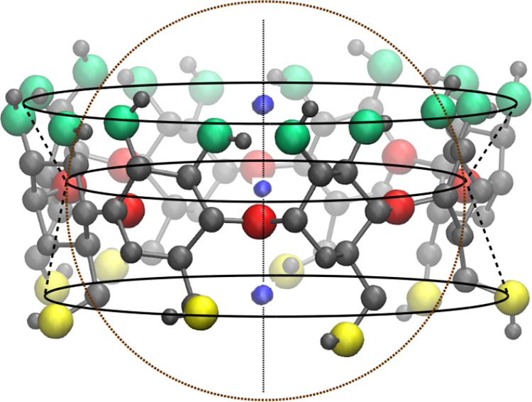
VMD snapshot of γ-CD showing the conical hourglass structure of the CD cavity as radius of glycosidic rim (O1 atoms—red spheres) is smaller than the outer secondary hydroxyl rim (O2 and O3 atoms—green spheres) and the primary hydroxyl rim (O6 atoms—yellow spheres). The small blue spheres are the centers of mass of O2 atoms, O1 atoms, and O6 atoms; the three centers of mass are collinear. The height of the bottom cone (0.31 nm) is larger than the height of the top cone (0.24 nm). The dotted circle represents the spherical region of O1 rim radius, demonstrating that such spherical approximation of cavity significantly deviates from the actual cavity geometry.
Energetics of Cavity Confined Waters are Correlated to Their Hydrogen Bonding Deficiency
As shown in Figure 4a, we can see that the rdf of water molecules about the CD center, g(r), goes through a maximum at two regions with an intervening regime of low water density. The first peak, typically, corresponds to water inside the CD cavity, while the second peak corresponds to the first hydration layer of the outer CD surface. The mid-point of the intervening regime between the peaks matches with the position of the CD wall. It is a common practice to compute the average water occupancy inside CD cavity by integrating the rdf up to the position of the CD wall. The radial cut-off distance corresponding to the CD wall and the average water occupancy in CD cavity obtained from rdf are tabulated in Table 3. These values closely agree with other simulation studies.35,45,46
Figure 4.

(a) Radial distribution function for oxygen of water molecules around the geometric center (center of mass) of native CDs. The dashed vertical lines represent the radial cut-off distances corresponding to the CD wall from their respective centers, used to calculate the water coordination number in the inner region of CD ring. (b) Probability distribution of water occupancy (nw) inside the cavity of native CDs as identified by our geometry-based approach. Color code: green—α-CD; blue—β-CD, and red—γ-CD.
Table 3. Comparison of the Computed Average Water Occupancy Inside CD Cavity, Determined from Radial Distribution Function (Nrdf) of Water Molecules Around CD Center and from Our New Geometry-Based Approach (Ngeom), against the Experimental Values (Nexpt).
The inner cavity of a CD is highly nonspherical—cavity is centrally constricted and the outer hydroxyl rims are not equidistant from the CD center. In such a case, the coordination number obtained from rdf would be misleading as it could include water molecules outside the hydroxyl rims and may exclude some water molecules closer to the CD inner wall at the broader rims. The dotted circle, as shown in Figure 3, represents the cavity volume considered by the rdf approach, we can notice the difference between the spherical volume and the actual volume of the cavity. In order to obtain an accurate estimate of the water molecules confined within the cavity, we developed a new geometry-based approach (see the Methods section) to count water molecules inside the cavity, incorporating the structural fluctuations of the CD molecule.
Figure 4b shows the probability distribution of water occupancy inside CD cavity determined by our new approach, with an increase in the CD size, the cavity can accommodate more water molecules, and hence, the mean increases and the probability distribution of water occupancy becomes broader. We find the maximum occupancy of water inside the cavity as 5 in α-CD, 9 in β-CD, and 14 in γ-CD. The actual position of these water molecules is shown in Figure 5, clearly revealing that all identified waters are totally inside the cavity. In a rigid fully open α-CD53 and β-CD54 with all primary hydroxyl groups pointing outward, that is, in gg conformation, a maximum of 6 and 10 water molecules, respectively, were able to be inserted inside the cavity without distorting the CD structure. In those studies, at every insertion, the position of the water was identified after energy optimization through DFT. Despite the structural variations observed in our MD simulations, the computed maximum occupancies in the native CDs are only one water molecule less than that reported by the DFT studies.
Figure 5.
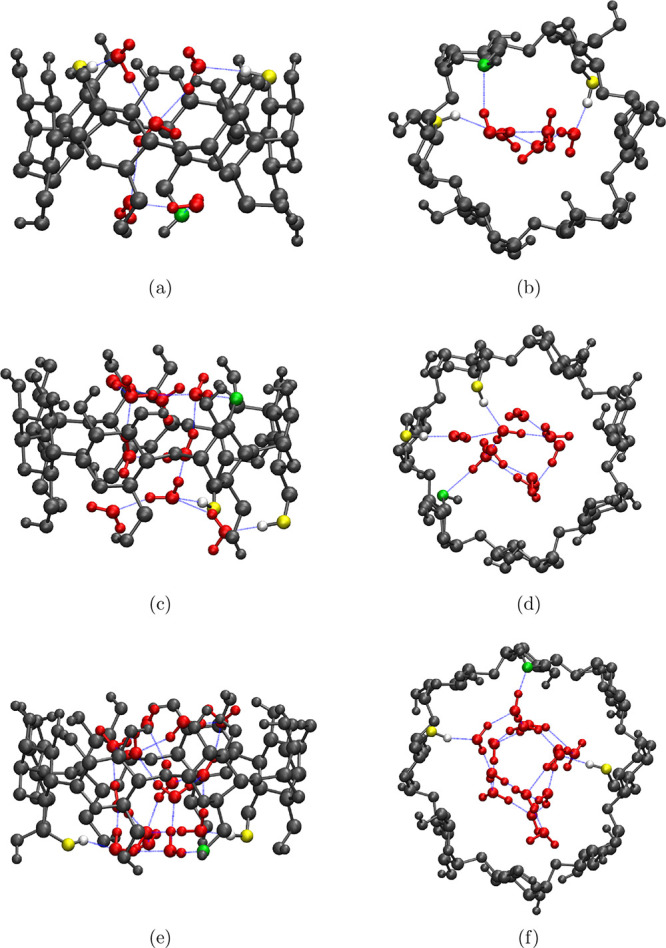
VMD snapshots showing the structure of native CDs (gray CPK representation) when maximum number of water molecules (red CPK representation)—5 in α-CD (a,b); 9 in β-CD (c,d); and 14 in γ-CD (e,f)—are occupying their cavity. Blue lines correspond to hydrogen bonds, green and yellow spheres are the CD heavy atoms accepting and donating (the associated hydrogen is shown in white) hydrogen bonds, respectively, with the cavity waters. Side view—a,c and e; the bottom view—b,d and f.
The average water occupancy inside CD cavity, computed from our simulations by the two techniques—rdf and geometry-based approach—is compared to the crystallography data, as listed in Table 3. The values obtained from the rdfs are greater than those obtained from the geometry-based approach and the experimental values because the spherical volume considered in computing water coordination from rdf is larger than the actual cavity volume (see Figure 3). The water occupancy determined from the geometric method matches very well with the experimental value for α-CD and γ-CD, but the computed water occupancy inside β-CD is lower than the experimental value by two water molecules. A couple of MD simulations have reported the water coordination number determined from the cylindrical rdf, definitely a better approximation than a spherical rdf, as 4.8539 and 5,40 respectively. The water sites reported by the diffraction study of α-CD and γ-CD crystals are completely inside their respective cavities; the former being a small well-defined cavity and in the latter, rims were occluded by the neighboring CD molecules in the crystal packing. On the other hand, a closer look into the X-ray-resolved β-CD structure (see Figure 1 in ref (28)) reveals that out of eight possible water sites, only three water sites are completely inside the CD cavity, while other five sites near the outer rims are only partly inside the CD cavity. The authors have, indeed, reported that the water sites near the secondary (O2 and O3) and the primary hydroxyl (O6) rims are adjacent to the hydroxyl groups of the neighboring β-CD molecules in the crystal. When we correct the occupancies of those five water sites near the outer rims to half of their reported occupancy values, as they are shared between neighboring β-CD molecules, the resultant average water occupancy turns out to be 4.5. Although, it could be fortuitous that the water occupancy obtained after the crude correction matches exactly with our results, the point we wanted to put across is that the crystallography value of 6.5 is, actually, an overestimation as the water molecules near the outer hydroxyl rims are shared between adjacent β-CD molecules in the crystal.
Water molecules trapped inside a supramolecular cavity are usually referred as activated or high-energy waters,3,33,34,57 the number of hydrogen bonds formed by the cavity water is considered to be the key parameter characterizing the extent of energetic frustration of such waters. Figure 6 compares the probability distribution of the number of hydrogen bonds formed by water inside the CD cavity to that in bulk water. The geometric condition as defined earlier is used to identify a hydrogen bond. In bulk solvent, a SPC/E water molecule on an average forms 3.6 hydrogen bonds, whereas a water molecule confined inside the cavity of α-CD, β-CD, and γ-CD forms only 1.5, 1.9, and 2.2 hydrogen bonds, respectively. The ability to form more hydrogen bonds in bulk medium is believed to be a major driving force for the water molecules to readily leave the cavity,33 enabling the encapsulation of a hydrophobic solute in the cavity. We have also observed that the water molecules that are trapped inside cavity prefer to form hydrogen bonds with the neighboring water molecules (Figure 5). Although, a glucose unit of CD forms about 4–5 hydrogen bonds with water molecules, the probability of a cavity water forming hydrogen bond with a CD atom is found to be only 20–35%. It is worth noting that the probability of the cavity to be occupied by a single water is very low, even in smaller α-CD cavity (Figure 4b). This preferential hydrogen bonding of confined water molecules among itself results in localization of water molecules in the central cylindrical region about the CD molecular axis (Figure 5).
Figure 6.

Comparing the probability distribution of number of hydrogen bonds, nHB, per water molecule inside CD cavity to that in bulk water. Color code: green—α-CD; blue—β-CD; red—γ-CD; and magenta—bulk water.
A detailed understanding of the thermodynamics of water inside cavity can be deduced from the binding energies and the excess solvation chemical potentials. The probability distribution of binding energies of water molecules inside CD cavity and in neat water is shown in Figure S1 in the Supporting Information For a water trapped in CD cavity, the distribution of binding energies is seen to be shifted to the right of the corresponding distribution for bulk water, that is, toward higher energies. With a decrease in the cavity size, the energy distribution is further shifted to the right. From Table 4, we can notice that the average interaction energy is negative (attractive interaction) in all systems, but the interaction energy is less attractive for a water molecule confined within CD cavity. Furthermore, the interaction energy becomes less attractive with a decrease in the cavity size. The hydrophobic nature of CD cavity is well known,2−4 only the outer rims are hydrophilic in nature. It is quite compelling to attribute the decrease in average binding energy of a water molecule confined in CD cavity to the hydrophobic nature of the cavity. The dispersion and electrostatic contributions of the binding energies, however, reveal a contrasting phenomenon. For a water molecule, either in bulk medium or confined in CD cavity, the dispersion interaction is repulsive in nature and it is the attractive electrostatic interaction that leads to an attractive mean binding energy (Table 4). Inside the cavity, the dispersion energy of a water molecule is less repulsive than that in bulk, indicating an attractive interaction between CD atoms and the water molecule. The increase in the CD–water dispersion attraction, however, could not offset the decrease in the attractive electrostatic interaction in the confined environment, ultimately leading to low binding energy for a confined water.
Table 4. Energetics of a Water Molecule Confined in CD Cavity and in Neat Water.
| system | ϵvdW (kJ/mol) | ϵelec (kJ/mol) | ϵ (kJ/mol) | μwex (kJ/mol) |
|---|---|---|---|---|
| α-CD | 8.8 ± 0.2 | –89.5 ± 0.7 | –80.6 ± 0.6 | –22.5 ± 2.8 |
| β-CD | 11.6 ± 0.1 | –95.3 ± 0.1 | –83.7 ± 0.3 | –25.1 ± 2.2 |
| γ-CD | 13.6 ± 0.1 | –101.6 ± 0.1 | –88.0 ± 0.1 | –27.0 ± 2.3 |
| neat water | 18.0 ± 0.02 | –110.8 ± 0.03 | –92.8 ± 0.02 | –29.8 ± 0.3 |
To understand the positional dependence of the interaction energy of a water molecule in CD cavity, we computed the average binding energy of water near a CD heavy atom from the binding energies of the cavity water molecules proximal to that atom. Figure 7 shows the surface plot of all native CDs colored according to the average binding energy of water near the surface relative to the average binding energy of a water molecule in bulk medium. As a CD cavity is constricted in the middle, it is not possible to obtain a complete view of the cavity through one perspective, so we have provided two views—one through the secondary hydroxyl rim (top view) and the other through the primary hydroxyl rim (bottom view). We can notice the blue region in the middle of the cavity in all native CDs, representing the unfavorable interaction energy of a water molecule in the cavity center because the hydrogen bond network of a water molecule is maximally compromised in that position. With an increase in the CD size, the water occupancies inside the cavity increase and, thereby, the number of hydrogen bonds per water molecule increases, hence, the interaction energies of water molecules in the cavity center becomes less unfavorable as revealed by the decrease in the intensity of the blue shade in the CDs. At this juncture, it is worth mentioning that because of the observed shift in the distribution of water binding energies (Figure S1), the range of water binding energies are slightly different among the CDs; therefore, the intensity of the color in the surface plots may not represent the absolute average binding energy of water in a site. The observed color gradient in a molecule, however, is a true representative of the energy gradient across the CD cavity.
Figure 7.
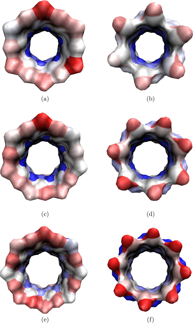
VMD snapshots showing the colored surface of the cavity of native CDs—α-CD (a,b); β-CD (c,d); and γ-CD (e,f)—showing the gradient in the average binding energy of water proximal to the CD surface relative to the average binding energy of water in bulk medium. Top view (perspective through the secondary hydroxyl rim)—a,c and e; the bottom view (perspective through the primary hydroxyl rim)—b,d and f. The colors red, white, and blue correspond to favorable, comparable, and unfavorable binding energies, respectively, with respect to the average binding energy in bulk water.
Both the outer rims of the CDs are pink/red colored, indicating favorable interaction energies of water molecules near the rims, as those water molecules can interact with rim hydroxyl groups and other water molecules outside the CD cavity. It is interesting to find that the interaction energy of water near the primary hydroxyl rim is comparatively less favorable than that near the secondary hydroxyl rim of α-CD, in contrast to the observation of more favorable water interaction near the primary hydroxyl rims of β-CD and γ-CD than that near their secondary hydroxyl rims. This is predominantly attributable to the conformation of the hydroxyl groups in the primary hydroxyl rim—gg vs gt conformations. In the case of α-CD, the primary hydroxyl groups majorly point outward of CD cavity (gg conformation), so they cannot interact with the cavity confined water molecules. On the other hand, the increase in the population of the inward pointed hydroxyl groups in the primary hydroxyl rims of the β-CD and γ-CD promotes favorable hydrogen bonding between cavity water and the primary hydroxyl groups (as seen in Figure 5d,f). Indeed, because of stiff intramolecular hydrogen bonds in the secondary hydroxyl rim, the interaction energy of the water molecules near the secondary hydroxyl rims is pretty much equivalent in all native CDs.
Using histogram overlap technique,58,59 we calculated the excess free energy of solvation, μwex, of a water molecule in CD cavity and in bulk (Figure 8a). The computed μw for bulk water is 29.8 kJ/mol, although it is at the higher end, it is in reasonable agreement with other SPC/E free-energy calculations within an error of 1 kBT.60−62 The excess chemical potentials of solvation of a water molecule in CD cavities (Table 4) are also negative but higher than the bulk water, it follows the order: μw,α-CDex > μw,β-CD > μw,γ-CDex. The associated error (2.2–2.8 kJ/mol ∼ 1 kBT) in the estimation of the μw of water in CD cavities is, however, comparatively higher than that for bulk water (0.3 kJ/mol ≪ 1 kBT) as the number of cavity confined water molecules is low. Indeed, the associated error is the highest for α-CD as the water occupancy inside the cavity of α-CD is the lowest.
Figure 8.

(a) Estimation of the excess solvation chemical potential of a water molecule, inside CD cavity and in bulk water, from the histogram overlap method. Color code: green—α-CD; blue—β-CD; red—γ-CD, and magenta—bulk water. (b) Difference in the binding energies (Δϵ = ϵw,cavity – ϵw,bulk) and the excess chemical potentials of solvation (Δμex = μw,cavityex – μw,bulk) of a water molecule in CD cavity and in bulk water are strongly correlated to the hydrogen bond deficiency of the intra cavity water molecule. Color code: blue—Δϵ and magenta—Δμex. Symbols are the simulation data, and the lines are the linear fit.
In aqueous solution, water in CD cavity exists in dynamic equilibrium with bulk water, hence, the chemical potential of water in either regions is equal: μw,cavity = μw,bulk. The chemical potential of a water in a region, μw,region, comprises an ideal contribution (first two terms on the right) and the excess contribution (the last term)
| 1 |
The first term μ0(T) depends only on temperature, accounting for the translational motion and internal degree of freedom of a molecule. One can, therefore, determine the difference between the excess chemical potentials of water in CD cavity and in bulk water from their corresponding water densities
| 2 |
Although we know the average water occupancy in CD cavity (Table 3), it is difficult to compute the average density of water inside CD cavity without an accurate estimation of the volume of the CD cavity. We have approximately calculated the cavity volume as the sum of the volumes of the top and bottom truncated cones (see the Supporting Information), however, such a calculation does not incorporate the fluctuations into the cavity volume observed during the simulation. The difference in the excess chemical potentials of water computed from the approximate average water density in CD cavity is tabulated in Table 5 and is compared against those values obtained from the histogram overlap method. We can notice that the estimates from both the approaches are comparable within the associated error of histogram overlap estimate. The observed deviation between the average values, especially the larger deviation in the case of α-CD, is partly due to the large error limit on the histogram overlap estimate, owing to low number of water molecules confined inside the cavity, and partly due to the inaccuracy in computing the cavity volume by ignoring the actual fluctuations in the CD structure.
Table 5. Energetics of Water in CD Cavity Relative to Bulk Water Propertiesa.
| system | Δϵ (kJ/mol) | Δ1μwex (kJ/mol) | Δ2μwex (kJ/mol) |
|---|---|---|---|
| α-CD | 12.2 | 7.3 | 5.1 |
| β-CD | 9.1 | 4.7 | 4.0 |
| γ-CD | 4.8 | 2.8 | 3.1 |
Inside a CD cavity, a water molecule forms a fewer number of hydrogen bonds. Because the environment in the cavity is not conducive to complete the water hydrogen bond network, the binding energy and excess chemical potential of water in CD cavity are less favorable compared to that in bulk water. Figure 8b shows the strong correlation between the energetics of water in CD cavity relative to bulk water and the difference in the number of hydrogen bonds formed by the cavity water and the bulk water. The intra cavity water molecules are, indeed, energetically frustrated, as commonly referred to as activated or high-energy waters,3,33,34 because of their hydrogen bond deficiency. It is interesting to note that the difference between the excess chemical potentials of water in CD cavity and in bulk is comparatively less unfavorable than the corresponding difference in the binding energies (Table 5). The trend is the same irrespective of the difference in the average values of Δμwex obtained from the two approaches. The observation suggests that the excess entropy of water inside the cavity is comparatively favorable than that in bulk water.
The local structure around a water molecule would definitely provide some insights into the entropy of water, so we computed the tetrahedral order parameter for a water molecule in bulk and in cavity. The distribution of probability density of tetrahedral order parameter (Figure 9) for bulk water, q4,i, is bimodal with a primary peak of about 0.8 and a secondary peak of about 0.5, in agreement with the earlier reports.63,64 In bulk water, the order parameter spans in the range (0,1); on the other hand, the order parameter of the cavity water varies in the range (−1,1) with a significant fraction of negative values. The order parameter becomes negative when some of the neighboring atoms (j and k) around the central molecule (i) make an acute angle (θjik < π/2). While all the nearest neighbors of a water molecule in bulk medium are water molecules, the nearest neighbor of the cavity could be neighboring intra cavity water molecules and/or the heavy atoms on the CD inner wall. The ratio corresponding to the average number of nearest atom of a cavity water being the neighboring intra cavity water oxygens (nwo) to that being the heavy atoms of the CD wall (nCD) i.e.,nwo/nCD is 1.3/2.7 in α-CD, 2.4/1.6 in β-CD, and 3.1/0.9 in γ-CD. While the average tetrahedral order parameter of bulk water is 0.64, the average value of the order parameter for a cavity water drops to 0.21 in γ-CD, further it drops to 0.13 in β-CD and almost vanishes with a value of 0.06 in α-CD. An earlier MD study has also reported a significant reduction in the tetrahedral order parameter for cavity confined water molecules.43 The lowering of tetrahedral order parameter implies an increase in the orientational degree of freedom for the water molecules confined in CD cavity, confirming the higher entropy of a water molecule inside CD cavity compared to that in bulk medium.
Figure 9.

Comparing the probability density of tetrahedral order parameter, q4,i, of a water molecule inside CD cavity to that in bulk water. The probability of finding the parameter, q4,i, in an interval (a,b) can be obtained by integrating the probability density distribution: P(a ≤ q4,i ≤ b) = ∫abP̃(q4,i)dq4,i. Color code: green—α-CD; blue—β-CD; red—γ-CD; and magenta—bulk water.
During complexation of a drug in CD cavity, the expulsion of water molecules from the CD cavity is the primary step. When a water molecule moves from the CD cavity to bulk medium, because of the increase in the number of hydrogen bonds, both the binding energy and the excess chemical potential of water become more favorable, but the orientational degree of freedom of a water molecule gets compromised because of the higher tetrahedral order parameter in bulk medium. This suggests that CD-drug complexation would be enthalpically driven, however, one needs to consider the entropy and the enthalpy change associated with the CD-drug interactions and the desolvation of the drug from the aqueous solution.
Conclusions
Cyclization of α-glucose molecules into CD alters the molecular conformation of α-glucose molecules to avoid steric clashes. The primary hydroxyl groups predominantly assume gg conformation, with the hydroxyl groups pointing outward of the CD macrocycle, enabling the interaction and hydrogen bonding of CD atoms with waters in the outer hydration layer. The significant conformational change for one of the secondary hydroxyl group (O3H3) makes O3 a better hydrogen bond donor than O2. The force field GROMOS 56A6Carbo_R correctly models the polygonal arrangement and the conformational changes of the primary (O6H6) and the secondary (O3H3) hydroxyl groups of the α-glucose molecules in the CD macrocycle. All native CDs were found to adopt a round symmetric structure with about n – 1 intramolecular CD–CD hydrogen bonds in the secondary rim, where n corresponds to the number of glucose in the CD molecule. NMR and diffraction experiments suggest that the rigidity of β-CD, comparative to α-CD or γ-CD structures, is due to the higher stability of its intramolecular hydrogen bonds, ascribing the low solubility of β-CD in water. The equivalent degree of intramolecular hydrogen bonding and the rigidity of the secondary hydroxyl rims of the CDs, observed in our simulations, may not reproduce the difference in aqueous solubility of the CDs appropriately, hence, certain special modification in the molecular model might be necessary.
Although the outer CD surface is in the shape of a hollow truncated cone, the positioning of the glycosidic oxygen to maintain the polygonal symmetry of a CD centrally constricts the inner surface, making the CD cavity to look like a conical hourglass. The heights of the two cones are not equal, even though CD is radially symmetric, it is highly asymmetrical along its height. Most commonly used approach of estimating cavity occupancy from the radial distribution function of water about the CD center would definitely over predict the cavity hydration. In this work, we have developed a simple geometry-based approach to identify intra cavity waters, incorporating the instantaneous fluctuation of the CD structure. The average and maximal water occupancies inside CD cavity closely match with the crystallography and DFT studies, respectively. As expected, the cavity waters formed lesser number of hydrogen bonds than the bulk water, and the number of hydrogen bonds is found to decrease with decrease in the CD size. Water molecules trapped inside cavity tend to hydrogen bond among themselves, reflecting the associative nature of water, eventually, leading to localization of waters in the central cylindrical region; this perhaps explains the close agreement of water occupancy determined by our technique with that of the cylindrical rdf approach.
In aqueous solution, water in CD cavity exists in dynamic equilibrium with that in bulk medium, however, the confined water molecules are energetically frustrated. The mean binding energy of water inside CD cavity is unfavorable compared to bulk water, owing to the decrease in the attractive electrostatic interactions inside CD cavity, which the attractive CD–water dispersion interaction could not offset. The hostile environment inside CD cavity is due to the reduction in the number of hydrogen bonds for the confined water, manifested by the strong correlation between the energetics of cavity confined water molecules and their hydrogen bond deficiency. The extent of gain in excess chemical potential, when a water molecule moves out of CD cavity, is less than the gain in binding energy, indicating the excess entropy of water inside the cavity to be higher. The drastic reduction in the tetrahedral order parameter of water molecules in CD cavity, which almost vanishes in the α-CD cavity, clearly reveals the increase in the orientational degree of freedom for water in CD cavity.
Finally, we would like to point out that our results have significant implications to the process of encapsulation of a hydrophobic drug in CD cavity. While accommodating a drug molecule inside CD cavity, the intra cavity water molecules are expelled to bulk medium. Such water molecules, due to increase in number of hydrogen bonds in bulk medium, would gain enthalpy and lose some orientational degree of freedom. Hence, CD-drug complexation would be mainly enthalpically driven unlike a classical entropically driven hydrophobic interactions. Of course, one cannot neglect the work required to desolvate the drug from aqueous solution or direct CD-drug interactions, which are out of scope of the current study.
Methods
Simulation Details
MD simulations of native CDs—α-CD, β-CD, and γ-CD—in water were performed with the GROMOS 56A6Carbo_R force field50 for CDs and the SPC/E water model65 using GROMACS simulation package (version 4.6.5). The cyclic structure of α-CD (pdb ID: 4fem.pdb),66 β-CD (pdb ID: 3cgt.pdb),67 and γ-CD (pdb ID: 5e70.pdb)68 were obtained from the protein data bank. Simulation of a single α-glucose in the SPC/E water box was also carried out to compute the conformational properties of a free monomeric glucose. Each system was energy minimized upto 500 steepest descent steps followed by a short 100 ps equilibration at NVT conditions using a Berendsen thermostat69 at 298 K. An NPT run of 1 ns was carried out at 298 K and 1 bar using the Nose–Hoover Thermostat70 and Parrinello Rahman barostat71 to equilibrate the system. All bonds were constrained using LINCS algorithm. Dispersion interactions were truncated at 1 nm. PME was used for electrostatic interactions with a real space cut off of 1 nm. MD integration time-step of 2 fs was used. Finally a production run of 30 ns under NVT conditions at 298 K was carried out. The configurations saved every 5 ps of the production run were used for further analysis. The average and the standard deviation for the computed properties were obtained from block averaging by splitting the trajectory of production run into three blocks of 10 ns each. For calculation of bulk water properties, 30 ns NPT simulation of a well-equilibrated 512 water box was carried out with the same simulation protocol, as listed above for CD–water simulation.
Procedure to Identify Cavity Water
We have incorporated the geometrical dimension of the CD cavity in identifying a cavity water. The cavity resembles a conical hourglass with its geometric center coinciding with the center of the mass of the glycosidic oxygens (O1). The centers of mass of the primary hydroxyl oxygens (O6), the glycosidic oxygens (O1), and the secondary hydroxyl oxygens (O2) are observed to be fairly collinear, with an average angle between the three centers of mass being 172°. The line passing through these center of mass, therefore, can be considered as the central molecular axis of CD. Our stepwise procedure, to identify cavity waters, is as follows: first, for every water molecule in the system, we calculate the distance between the water oxygen and centers of mass of O1 rim, O2 rim, and O6 rim to determine the nearest center of mass for the water molecule. Second, we check whether the distance between the nearest center of mass and the water oxygen is less than the corresponding rim radii. If so, then we calculate the vertical height of water oxygen and both the hydrogens of the water molecule from the CD center (O1 center of mass). The vertical height of an atom is computed as the magnitude of the projection of the vector connecting the atom and the CD center, along the central molecular axis. Finally, if the vertical height of any atom of the water molecule is less than the height of the nearest center of mass of the either outer rims (O2 rim or O6 rim), that is, either h12 or h16, then the water molecule is identified to be within the CD cavity. When O1 center of mass is identified as the nearest center of mass for a water molecule, it is not necessary to determine the vertical height, it is just sufficient to check whether the radial distance between the water oxygen and the O1 center of mass is less than the O1 rim radii. To account for the flexibility of the CD structure, the calculation of the center of mass of the rims, heights of the both conical sections, and the radii of every rim were computed for every frame of the production run.
Excess Chemical Potential
We have computed the excess chemical potential of solvation of a water in CD cavity and in bulk water through the histogram overlap method,58,59 that is, by curve fitting the overlapping region of the histograms of the interaction energy for the removal and the insertion of a water molecule from/in to the system. The theory is briefly discussed here. The excess chemical potential of solvation of a molecule is directly related to the distribution of binding energy P(ϵ) of the molecules
| 3 |
β ≡ 1/kBT is the inverse of the product of the Boltzmann constant (kB) and the system temperature (T). The binding energy (ϵ) of a molecule is the interaction energy of the chosen molecule with the rest of the molecules in the system; in other words, it is the energy required to remove the chosen molecule from the system. The excess chemical potential can also be obtained from the distribution of the potential energy required to insert a molecule, P0(ϵ), into the system
| 4 |
The subscript 0 in the second term ⟨···⟩0 implies that the averaging is done over the configurations of the original unperturbed system, that is, the inserted molecule and the system are considered to be uncoupled. It is to be noted that in the eq 3, the chosen water molecule is coupled to the rest of the system. From these equivalent definitions of the excess chemical potential μex, one can obtain the relationship between the distribution of potential energies in the coupled and the uncoupled systems
| 5 |
Using this identity, the excess chemical potential of solvation can be determined as the intercept by linear fitting kBTln(P(ϵ)/P0(ϵ)) to −ϵ.
The histograms for the binding energy of a water molecule, P(ϵ), and inserted water molecule, P0(ϵ), inside CD cavity and in neat water were computed using our in-house programs. The binding energy was calculated as a sum of dispersion interactions and electrostatic interactions of a given water molecule (a chosen water molecule or an inserted water molecule) with the rest of the system. The dispersion interactions were computed by the truncation scheme, and electrostatic interactions were computed through the generalized reaction field scheme with appropriate finite box size correction.72 A cut off distance of 1.2 nm was used for both dispersion and electrostatic interactions. In CD–water simulation, 1000 water molecules were randomly inserted inside the CD cavity in every frame at different orientations. The inserted water molecule was ensured to be within the CD cavity as per the criteria defined by our geometry-based approach for cavity water. In the case of neat water simulation, a three-dimensional grid network was constructed at a distance of every 2 Å, and a water molecule at random orientation was inserted at every grid point, resulting in a insertion of 1728 water molecules in every frame.
Tetrahedral Order Parameter
The tetrahedral order parameter characterizing the local structure of a chosen water molecule, based on the orientation of its four nearest neighbors, is defined73 as
| 6 |
where θjik is the angle formed by neighbors j and k with the central molecule i, and the summation involves six such angles. The possible range for the tetrahedral order parameter of a molecule is −3 ≤ q4,i ≤ 1. The normalization factor of 3/8 in eq 6, however, ensures that the ensemble averaged tetrahedral order parameter, ⟨q4⟩, spans in the range 0 ≤ ⟨q4⟩ ≤ 1. The value of 1 corresponds to a perfect tetrahedral arrangement of neighboring molecules about the central molecule, while the value of 0 indicates a random mutual arrangement of molecules as in an ideal gas. While identifying the nearest neighbors for a water molecule inside CD cavity, we have considered all closest heavy atoms, that is, other intra cavity water oxygens and/or the heavy atoms of the CD inner wall.
Acknowledgments
We thank the High Performance Computing Environment (HPCE), IIT Madras for providing the computational resources.
Supporting Information Available
The Supporting Information is available free of charge at https://pubs.acs.org/doi/10.1021/acsomega.0c02760.
Radii of various rims of native CDs; probability distribution of binding energies of water inside CD cavity and in neat water; and cavity volume and the average water density in CD cavity (PDF)
The authors declare no competing financial interest.
Supplementary Material
References
- Saenger W. Cyclodextrin Inclusion Compounds in Research and Industry. Angew. Chem., Int. Ed. 1980, 19, 344–362. 10.1002/anie.198003441. [DOI] [Google Scholar]
- Szejtli J. Introduction and General Overview of Cyclodextrin Chemistry. Chem. Rev. 1998, 98, 1743–1754. 10.1021/cr970022c. [DOI] [PubMed] [Google Scholar]
- Connors K. A. The Stability of Cyclodextrin Complexes in Solution. Chem. Rev. 1997, 97, 1325–1358. 10.1021/cr960371r. [DOI] [PubMed] [Google Scholar]
- Saenger W.; Jacob J.; Gessler K.; Steiner T.; Hoffmann D.; Sanbe H.; Koizumi K.; Smith S. M.; Takaha T. Structures of the Common Cyclodextrins and Their Larger Analogues Beyond the Doughnut. Chem. Rev. 1998, 98, 1787–1802. 10.1021/cr9700181. [DOI] [PubMed] [Google Scholar]
- Betzel C.; Saenger W.; Hingerty B. E.; Brown G. M. Topography of cyclodextrin inclusion complexes, part 20. Circular and flip-flop hydrogen bonding in .beta.-cyclodextrin undecahydrate: a neutron diffraction study. J. Am. Chem. Soc. 1984, 106, 7545–7557. 10.1021/ja00336a039. [DOI] [Google Scholar]
- Shahidi F.; Han X. Q. Encapsulation of Food Ingredients. Crit. Rev. Food Sci. Nutr. 1993, 33, 501–547. 10.1080/10408399309527645. [DOI] [PubMed] [Google Scholar]
- Szente L.; Szejtli J. Cyclodextrins as Food Ingredients. Trends Food Sci. Technol. 2004, 15, 137–142. 10.1016/j.tifs.2003.09.019. [DOI] [Google Scholar]
- Hicks K. B.; Sapers G. M.; Seib P. A.. Process for Preserving Raw Fruit and Vegetable Juices using Cyclodextrins and Compositions thereof. U.S. Patent 4,975,293 A, 1990.
- Alonso L.; Cuesta P.; Fontecha J.; Juarez M.; Gilliland S. E. Use of β-cyclodextrin to decrease the level of cholesterol in milk fat. J. Dairy Sci. 2009, 92, 863–869. 10.3168/jds.2008-1452. [DOI] [PubMed] [Google Scholar]
- Buschmann H. J.; Schollmeyer E. Applications of Cyclodextrins in Cosmetic Products: A Review. J. Cosmet. Sci. 2002, 53, 185–192. [PubMed] [Google Scholar]
- Centini M.; Maggiore M.; Casolaro M.; Andreassi M.; Maffei Facino R.; Anselmi C. Cyclodextrins as Cosmetic Delivery Systems. J. Incl. Phenom. Macro. 2007, 57, 109–112. 10.1007/s10847-006-9212-0. [DOI] [Google Scholar]
- Numanoğlu U.; Şen T.; Tarimci N.; Kartal M.; Koo O. M. Y.; Önyüksel H. Use of Cyclodextrins as a Cosmetic Delivery System for Fragrance Materials: Linalool and Benzyl Acetate. AAPS PharmSciTech 2007, 8, 34–42. 10.1208/pt0804085. [DOI] [PMC free article] [PubMed] [Google Scholar]
- Crini G.; Morcellet M. Synthesis and Applications of Adsorbents Containing Cyclodextrins. J. Sep. Sci. 2002, 25, 789–813. . [DOI] [Google Scholar]
- Morin-Crini N.; Crini G. Environmental Applications of Water-Insoluble β-Cyclodextrin–Epichlorohydrin Polymers. Prog. Polym. Sci. 2013, 38, 344–368. 10.1016/j.progpolymsci.2012.06.005. [DOI] [Google Scholar]
- Trinh T.; Phan D. V.. Articles Containing Small Particle Size Cyclodextrin for Odor Control. U.S. Patent 5,429,628 A, 1995.
- Jency D. A.; Umadevi M.; Sathe G. V. SERS Detection of Polychlorinated Biphenyls Using β-Cyclodextrin Functionalized Gold Nanoparticles on Agriculture Land Soil. J. Raman Spectrosc. 2015, 46, 377–383. 10.1002/jrs.4654. [DOI] [Google Scholar]
- Patil N. V.; Netravali A. N. Cyclodextrin-Based “Green” Wrinkle-Free Finishing of Cotton Fabrics. Ind. Eng. Chem. 2019, 58, 20496–20504. 10.1021/acs.iecr.9b04092. [DOI] [Google Scholar]
- Singh M.; Sharma R.; Banerjee U. C. Biotechnological Applications of Cyclodextrins. Biotechnol. Adv. 2002, 20, 341–359. 10.1016/s0734-9750(02)00020-4. [DOI] [PubMed] [Google Scholar]
- Jambhekar S. S.; Breen P. Cyclodextrins in Pharmaceutical Formulations I: Structure and Physicochemical Properties, Formation of Complexes, and Types of Complex. Drug Discov. Today 2016, 21, 356–362. 10.1016/j.drudis.2015.11.017. [DOI] [PubMed] [Google Scholar]
- Zafar N.; Fessi H.; Elaissari A. Cyclodextrin Containing Biodegradable Particles: From Preparation to Drug Delivery Applications. Int. J. Pharm. 2014, 461, 351–366. 10.1016/j.ijpharm.2013.12.004. [DOI] [PubMed] [Google Scholar]
- Gidwani B.; Vyas A. A Comprehensive Review on Cyclodextrin-Based Carriers for Delivery of Chemotherapeutic Cytotoxic Anticancer Drugs. BioMed Res. Int. 2015, 2015, 198268. [DOI] [PMC free article] [PubMed] [Google Scholar]
- Qiu N.; Li X.; Liu J. Application of Cyclodextrins in Cancer Treatment. J. Incl. Phenom. Macro. 2017, 89, 229–246. 10.1007/s10847-017-0752-2. [DOI] [Google Scholar]
- Liu L.; Guo Q.-X. The Driving Forces in the Inclusion Complexation of Cyclodextrins. J. Incl. Phenom. Macro. 2002, 42, 1–14. [Google Scholar]
- Taulier N.; Chalikian T. V. Hydrophobic Hydration in Cyclodextrin Complexation. J. Phys. Chem. B 2006, 110, 12222–12224. 10.1021/jp062467n. [DOI] [PubMed] [Google Scholar]
- Tanford C.The Hydrophobic Effect: Formation of Micelles and Biological Membranes, 2nd ed.; Wiley-Blackwell, 1980. [Google Scholar]
- Manor P. C.; Saenger W. Topography of Cyclodextrin Inclusion Complexes. III. Crystal and Molecular structure of Cyclohexaamylose Hexahydrate, The Water Dimer Inclusion Complex. J. Am. Chem. Soc. 1974, 96, 3630–3639. 10.1021/ja00818a042. [DOI] [Google Scholar]
- Chacko K. K.; Saenger W. Topography of cyclodextrin inclusion complexes. 15. Crystal and molecular structure of the cyclohexaamylose-7.57 water complex, form III. Four- and six-membered circular hydrogen bonds. J. Am. Chem. Soc. 1981, 103, 1708–1715. 10.1021/ja00397a021. [DOI] [Google Scholar]
- Lindner K.; Saenger W. β-Cyclodextrin Dodecahydrate: Crowding of Water Molecules within a Hydrophobic Cavity. Angew. Chem., Int. Ed. 1978, 17, 694–695. 10.1002/anie.197806941. [DOI] [Google Scholar]
- Harata K. Crystal Structure of γ-Cyclodextrin at Room Temperature. Chem. Lett. 1984, 13, 641–644. 10.1246/cl.1984.641. [DOI] [Google Scholar]
- Harata K. The Structure of the Cyclodextrin Complex. XX. Crystal Structure of Uncomplexed Hydrated γ-Cyclodextrin. Bull. Chem. Soc. Jpn. 1987, 60, 2763–2767. 10.1246/bcsj.60.2763. [DOI] [Google Scholar]
- Ding J.; Steiner T.; Zabel V.; Hingerty B. E.; Mason S. A.; Saenger W. Topography of cyclodextrin inclusion complexes. 28. Neutron diffraction study of the hydrogen bonding in partially deuterated .gamma.-cyclodextrin.cntdot.15.cntdot.7D2O at T = 110 K. J. Am. Chem. Soc. 1991, 113, 8081–8089. 10.1021/ja00021a039. [DOI] [Google Scholar]
- Setny P.; Baron R.; McCammon J. A. How can Hydrophobic Association be Enthalpy Driven?. J. Chem. Theory Comput. 2010, 6, 2866–2871. 10.1021/ct1003077. [DOI] [PMC free article] [PubMed] [Google Scholar]
- Biedermann F.; Nau W. M.; Schneider H.-J. The Hydrophobic Effect Revisited—Studies with Supramolecular Complexes Imply High-Energy Water as a Noncovalent Driving Force. Angew. Chem., Int. Ed. 2014, 53, 11158–11171. 10.1002/anie.201310958. [DOI] [PubMed] [Google Scholar]
- Biedermann F.; Uzunova V. D.; Scherman O. A.; Nau W. M.; De Simone A. Release of High-Energy Water as an Essential Driving Force for the High-Affinity Binding of Cucurbit[n]urils. J. Am. Chem. Soc. 2012, 134, 15318–15323. 10.1021/ja303309e. [DOI] [PubMed] [Google Scholar]
- Raffaini G.; Ganazzoli F. Hydration and Flexibility of α-, β-, γ-and δ-Cyclodextrin: A Molecular Dynamics Study. Chem. Phys. 2007, 333, 128–134. 10.1016/j.chemphys.2007.01.015. [DOI] [Google Scholar]
- Cai W.; Sun T.; Shao X.; Chipot C. Can the Anomalous Aqueous Solubility of β-Cyclodextrin be Explained by its Hydration Free Energy Alone?. Phys. Chem. Chem. Phys. 2008, 10, 3236–3243. 10.1039/b717509d. [DOI] [PubMed] [Google Scholar]
- Naidoo K. J.; Chen J. Y.-J.; Jansson J. L. M.; Widmalm G.; Maliniak A. Molecular Properties Related to the Anomalous Solubility of β-Cyclodextrin. J. Phys. Chem. B 2004, 108, 4236–4238. 10.1021/jp037704q. [DOI] [Google Scholar]
- Naidoo K. J.; Gamieldien M. R.; Chen J. Y.-J.; Widmalm G.; Maliniak A. Glucose Orientation and Dynamics in α-, β-, and γ-Cyclodextrins. J. Phys. Chem. B 2008, 112, 15151–15157. 10.1021/jp805174y. [DOI] [PubMed] [Google Scholar]
- Yong C. W.; Washington C.; Smith W. Structural Behaviour of 2-Hydroxypropyl-β-Cyclodextrin in Water: Molecular Dynamics Simulation Studies. Pharm. Res. 2008, 25, 1092–1099. 10.1007/s11095-007-9506-y. [DOI] [PubMed] [Google Scholar]
- Rodriguez J.; Hernán Rico D.; Domenianni L.; Laria D. Confinement of Polar Solvents within β-Cyclodextrins. J. Phys. Chem. B 2008, 112, 7522–7529. 10.1021/jp711609q. [DOI] [PubMed] [Google Scholar]
- Khuntawee W.; Karttunen M.; Wong-ekkabut J. A Molecular Dynamics Study of Conformations of Beta-Cyclodextrin and its Eight Derivatives in Four Different Solvents. Phys. Chem. Chem. Phys. 2017, 19, 24219–24229. 10.1039/c7cp04009a. [DOI] [PubMed] [Google Scholar]
- Jana M.; Bandyopadhyay S. Microscopic Investigation of the Hydration Properties of Cyclodextrin and Its Substituted Forms. Langmuir 2009, 25, 13084–13091. 10.1021/la902003y. [DOI] [PubMed] [Google Scholar]
- Jana M.; Bandyopadhyay S. Hydration Properties of α-, β-, and γ-Cyclodextrins from Molecular Dynamics Simulations. J. Phys. Chem. B 2011, 115, 6347–6357. 10.1021/jp2013946. [DOI] [PubMed] [Google Scholar]
- Jana M.; Bandyopadhyay S. Kinetics of Hydrogen Bonds in Aqueous Solutions of Cyclodextrin and its Methyl-Substituted Forms. J. Chem. Phys. 2011, 134, 01B611. 10.1063/1.3530781. [DOI] [PubMed] [Google Scholar]
- Pereira C. S.; Moura A. F. d.; Freitas L. C. G.; Lins R. D. Revisiting the Internal Conformational Dynamics and Solvation Properties of Cyclodextrins. J. Braz. Chem. Soc. 2007, 18, 951–961. 10.1590/s0103-50532007000500012. [DOI] [Google Scholar]
- Cézard C.; Trivelli X.; Aubry F.; Djedaïni-Pilard F.; Dupradeau F.-Y. Molecular Dynamics Studies of Native and Substituted Cyclodextrins in Different Media: 1. Charge Derivation and Force Field Performances. Phys. Chem. Chem. Phys. 2011, 13, 15103–15121. 10.1039/c1cp20854c. [DOI] [PubMed] [Google Scholar]
- Damm W.; Frontera A.; Tirado-Rives J.; Jorgensen W. L. OPLS All-Atom Force Field for Carbohydrates. J. Comput. Chem. 1997, 18, 1955–1970. . [DOI] [Google Scholar]
- Kony D.; Damm W.; Stoll S.; van Gunsteren W. F. An Improved OPLS–AA Force Field for Carbohydrates. J. Comput. Chem. 2002, 23, 1416–1429. 10.1002/jcc.10139. [DOI] [PubMed] [Google Scholar]
- Hansen H. S.; Hünenberger P. H. A Reoptimized GROMOS Force Field for Hexopyranose-Based Carbohydrates Accounting for the Relative Free Energies of Ring Conformers, Anomers, Epimers, Hydroxymethyl Rotamers, and Glycosidic Linkage Conformers. J. Comput. Chem. 2011, 32, 998–1032. 10.1002/jcc.21675. [DOI] [PubMed] [Google Scholar]
- Plazinski W.; Lonardi A.; Hünenberger P. H. Revision of the GROMOS 56A6CARBO Force Field: Improving the Description of Ring-Conformational Equilibria in Hexopyranose-Based Carbohydrates Chains. J. Comput. Chem. 2016, 37, 354–365. 10.1002/jcc.24229. [DOI] [PubMed] [Google Scholar]
- Gebhardt J.; Kleist C.; Jakobtorweihen S.; Hansen N. Validation and Comparison of Force Fields for Native Cyclodextrins in Aqueous Solution. J. Phys. Chem. B 2018, 122, 1608–1626. 10.1021/acs.jpcb.7b11808. [DOI] [PubMed] [Google Scholar]
- Schneider H.-J.; Hacket F.; Rüdiger V.; Ikeda H. NMR Studies of Cyclodextrins and Cyclodextrin Complexes. Chem. Rev. 1998, 98, 1755–1786. 10.1021/cr970019t. [DOI] [PubMed] [Google Scholar]
- Angelova S.; Nikolova V.; Pereva S.; Spassov T.; Dudev T. α-Cyclodextrin: How Effectively Can Its Hydrophobic Cavity Be Hydrated?. J. Phys. Chem. B 2017, 121, 9260–9267. 10.1021/acs.jpcb.7b04501. [DOI] [PubMed] [Google Scholar]
- Pereva S.; Nikolova V.; Angelova S.; Spassov T.; Dudev T. Water Inside β-Cyclodextrin Cavity: Amount, Stability and Mechanism of Binding. Beilstein J. Org. Chem. 2019, 15, 1592–1600. 10.3762/bjoc.15.163. [DOI] [PMC free article] [PubMed] [Google Scholar]
- Shikata T.; Takahashi R.; Satokawa Y. Hydration and Dynamic Behavior of Cyclodextrins in Aqueous Solution. J. Phys. Chem. B 2007, 111, 12239–12247. 10.1021/jp0751864. [DOI] [PubMed] [Google Scholar]
- Onda M.; Yamamoto Y.; Inoue Y.; Chûjô R. 1H NMR Study of Intramolecular Hydrogen-Bonding Interaction in Cyclodextrins and Their Di-O-Methylated Derivatives. Bull. Chem. Soc. Jpn. 1988, 61, 4015–4021. 10.1246/bcsj.61.4015. [DOI] [Google Scholar]
- Georg H. C.; Coutinho K.; Canuto S. A Look Inside the Cavity of Hydrated α-Cyclodextrin: A Computer Simulation Study. Chem. Phys. Lett. 2005, 413, 16–21. 10.1016/j.cplett.2005.07.036. [DOI] [Google Scholar]
- Hummer G.; Rasaiah J. C.; Noworyta J. P. Water Conduction through the Hydrophobic Channel of a Carbon Nanotube. Nature 2001, 414, 188–190. 10.1038/35102535. [DOI] [PubMed] [Google Scholar]
- Bennett C. H. Efficient estimation of free energy differences from Monte Carlo data. J. Comput. Phys. 1976, 22, 245–268. 10.1016/0021-9991(76)90078-4. [DOI] [Google Scholar]
- Heidari M.; Kremer K.; Cortes-Huerto R.; Potestio R. Spatially Resolved Thermodynamic Integration: An Efficient Method to Compute Chemical Potentials of Dense Fluids. J. Chem. Theory Comput. 2018, 14, 3409–3417. 10.1021/acs.jctc.8b00002. [DOI] [PubMed] [Google Scholar]
- Knopp B.; Suter U. W.; Gusev A. A. Atomistically Modeling the Chemical Potential of Small Molecules in Dense Polymer Microstructures. 1. Method. Macromolecules 1997, 30, 6107–6113. 10.1021/ma970383u. [DOI] [Google Scholar]
- Kristóf T.; Rutkai G. Chemical Potential Calculations by Thermodynamic Integration with Separation Shifting in Adaptive Sampling Monte Carlo Simulations. Chem. Phys. Lett. 2007, 445, 74–78. 10.1016/j.cplett.2007.07.054. [DOI] [Google Scholar]
- Pereyra R. G.; Bermúdez di Lorenzo A. J.; Malaspina D. C.; Carignano M. A. On the Relation between Hydrogen Bonds, Tetrahedral Order and Molecular Mobility in Model Water. Chem. Phys. Lett. 2012, 538, 35–38. 10.1016/j.cplett.2012.04.022. [DOI] [Google Scholar]
- Bandyopadhyay D.; Mohan S.; Ghosh S. K.; Choudhury N. Correlation of Structural Order, Anomalous Density, and Hydrogen Bonding Network of Liquid Water. J. Phys. Chem. B 2013, 117, 8831–8843. 10.1021/jp404478y. [DOI] [PubMed] [Google Scholar]
- Berendsen H. J. C.; Grigera J. R.; Straatsma T. P. The missing term in effective pair potentials. J. Phys. Chem. 1987, 91, 6269–6271. 10.1021/j100308a038. [DOI] [Google Scholar]
- Cameron E. A.; Maynard M. A.; Smith C. J.; Smith T. J.; Koropatkin N. M.; Martens E. C. Multidomain Carbohydrate-binding Proteins Involved in Bacteroides thetaiotaomicron Starch Metabolism. J. Biol. Chem. 2012, 287, 34614–34625. 10.1074/jbc.m112.397380. [DOI] [PMC free article] [PubMed] [Google Scholar]
- Schmidt A. K.; Cottaz S.; Driguez H.; Schulz G. E. Structure of Cyclodextrin Glycosyltransferase Complexed with a Derivative of its Main Product β-Cyclodextrin. Biochemistry 1998, 37, 5909–5915. 10.1021/bi9729918. [DOI] [PubMed] [Google Scholar]
- Feng L.; Fawaz R.; Hovde S.; Sheng F.; Nosrati M.; Geiger J. H. Crystal Structures of Escherichia Coli Branching Enzyme in Complex with Cyclodextrins. Acta Crystallogr., Sect. D: Struct. Biol. 2016, 72, 641–647. 10.1107/s2059798316003272. [DOI] [PubMed] [Google Scholar]
- Berendsen H. J. C.; Postma J. P. M.; van Gunsteren W. F.; DiNola A.; Haak J. R. Molecular Dynamics with Coupling to an External Bath. J. Chem. Phys. 1984, 81, 3684–3690. 10.1063/1.448118. [DOI] [Google Scholar]
- Posch H. A.; Hoover W. G.; Vesely F. J. Canonical Dynamics of the Nosé Oscillator: Stability, Order, and Chaos. Phys. Rev. A: At., Mol., Opt. Phys. 1986, 33, 4253. 10.1103/physreva.33.4253. [DOI] [PubMed] [Google Scholar]
- Parrinello M.; Rahman A. Polymorphic Transitions in Single Crystals: A New Molecular Dynamics Method. J. Appl. Phys. 1981, 52, 7182–7190. 10.1063/1.328693. [DOI] [Google Scholar]
- Hummer G.; Pratt L. R.; García A. E. Free Energy of Ionic Hydration. J. Phys. Chem. 1996, 100, 1206–1215. 10.1021/jp951011v. [DOI] [Google Scholar]
- Errington J. R.; Debenedetti P. G. Relationship between Structural Order and the Anomalies of Liquid Water. Nature 2001, 409, 318–321. 10.1038/35053024. [DOI] [PubMed] [Google Scholar]
Associated Data
This section collects any data citations, data availability statements, or supplementary materials included in this article.