Abstract
The majority of 3D-printed biodegradable biomaterials are brittle, limiting their potential application to compliant tissues. Poly (glycerol sebacate) acrylate (PGSA) is a synthetic biodegradable and biocompatible elastomer, compatible with light-based 3D printing. In this work we employed digital-light-processing (DLP)-based 3D printing to create a complex PGSA network structure. Nature-inspired double network (DN) structures with two geometrically interconnected segments with different mechanical properties were printed from the same material in a single shot. Such capability has not been demonstrated by any other fabrication technique. The biocompatibility of PGSA after 3D printing was confirmed via cell-viability analysis. We used a finite element analysis (FEA) model to predict the failure of the DN structure under uniaxial tension. FEA confirmed the soft segments act as sacrificial elements while the hard segments retain structural integrity. The simulation demonstrated that the DN design absorbs 100% more energy before rupture than the network structure made by single exposure condition (SN), doubling the toughness of the overall structure. Using the FEA-informed design, a new DN structure was printed and the FEA predicted tensile test results agreed with tensile testing of the printed structure. This work demonstrated how geometrically-optimized material design can be easily and rapidly achieved by using DLP-based 3D printing, where well-defined patterns of different stiffnesses can be simultaneously formed using the same elastic biomaterial, and overall mechanical properties can be specifically optimized for different biomedical applications.
1. Introduction
Synthetically-derived biomaterials are often used for biomedical applications as they can be consistently produced and allow for control over mechanical properties, degradation rate, and functionalization. Furthermore, synthetically-derived biomaterials can be easily adapted for advanced manufacturing processes to form structures with complex geometry. Nonetheless, the majority of these biomaterials, such as polyethylene glycol diacrylate (PEGDA), do not have mechanical properties that appropriately mimic their intended tissue environment. Clinically-used synthetic biomaterials tend to be either too brittle or too soft, limiting their use in more compliant tissues such as skin, vasculature, muscle, and nerve. Tough and elastic biomaterials would allow for the development of scaffolds and devices with mechanical properties similar to tissues like skeletal muscle, which routinely goes through cycles of lengthening and shortening, has a specific tension between 125-250 kPa, and undergoes strains up to 40% [1-4]. Poly (glycerol sebacate) (PGS) has emerged as a tough biomaterial as well as a biodegradable elastomer [5-8]. PGS has been used for sutures, cardiac patches, and biosensors [9-11]. However, fabricating complex structures from PGS is still challenging due to its high viscosity and glass transition temperature. Therefore, most applications incorporating PGS are limited to molding and electrospinning fabrication techniques, which limits their structural complexity for applications such as tissue engineering, where patient-specific designs are of particular importance [5-7,12].
To increase the toughness of polymeric biomaterials, intensive studies have been recently conducted to integrate multiple materials with varying mechanical properties into one, which are known as double network (DN) polymers [13-16]. Inspired by natural silks, one network in the DN system is often soft and stretchable, and the other network is stiff and brittle [17,18]. As the DN structure is stretched, the softer network serves as a sacrificial material to dissipate energy while the harder network maintains the shape of the structure. Thus, the overall toughness of the network could be increased without additional material or increasing material density. Molecular-scale DN were conventionally made by interpenetrating polymer networks (IPNs), which consists of a blend of monomers with different functional groups. These monomers were then polymerized by different mechanisms, forming a network crosslinked by different types of bonds (i.e. ionic and covalent) [19]. However, such polymers require high homogeneity of the monomer as well as precisely controlled reaction conditions to achieve uniform polymerization [19]. Any defects due to heterogeneity of the monomer blending will introduce stress concentration, which will greatly affect the mechanical performance of the overall structure [16,20,21]. Inspired by IPNs, elastic structures could potentially consist of only one material if its mechanical properties could be altered by the fabrication method. Additionally, these distinct mechanical properties could be allocated at specific regions of the structure during fabrication, thus creating a DN possessing larger intrinsic length scales. However, fabricating a structure consisting of a single biomaterial with different material properties has not been accomplished.
3D printing has emerged as a powerful technology to fabricate complex structures. Specifically, DLP-based 3D printing can be used to crosslink photopolymerizable polymers into arbitrary, complex shapes with microscale resolution in mere seconds. Due to the scanningless and continuous nature of DLP printing, the lack of artificial interfaces between fabricated structures enhances mechanical integrity of the overall structure. We have previously demonstrated the ability to print complex structures out of polyethylene glycol diacrylate (PEGDA) with our DLP-based printing technology [22-30]. Furthermore, the mechanical properties of a 3D-printed structure can be digitally controlled by assigning different exposure conditions at distinct locations, resulting in a single continuous structure with multiple material properties [31]. Thus, a DN structure from a single material could be potentially fabricated using DLP-based 3D printing. Recently, Nijst et al. developed a technique to modify PGS with photocrosslinkable acrylate (PGSA) groups, which theoretically makes PGSA compatible with DLP-based 3D printing (Figure 1) [32]. Therefore, the first goal of this study was to adapt PGSA to be compatible with DLP-based 3D printing. Finite element analysis (FEA) was utilized to understand potential failure mechanisms of network structures and optimize the 3D printing parameters such as the network aspect ratio and stiffness ratio, in order to increase the network toughness while maintaining low mass density. Finally, SN and DN structures informed by the FEA results were 3D printed, and tensile testing of these structures confirmed that FEA predicted twofold increase in toughness of the DN structure over the SN.
Figure 1.
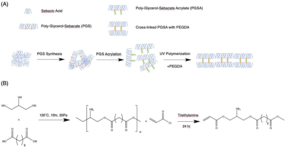
Schematic of polymerization and synthesis. (A) PGS was acrylated into PGSA, which was further crosslinked by UV polymerization in the presence of PEGDA. (B) PGS was synthesized by condensation between sebacic acid and glycerol at controlled pressure (35 Pa) and elevated temperature (120 °C) for 15 hours. The PGS was then acrylated by acryloyl chloride in the presence of Triethylamine (TEA) for 24 hours before purification by rotary evaporation.
2. Results and Discussion
2.1. Synthesis of PGSA
The successful synthesis of PGS and PGSA (Figure 1) was confirmed by 1H NMR (Supplementary Figure 1). The conversion rate of PGS synthesis was calculated to be 90% by weight change. The substitution by the acrylation group was confirmed by the chemical shifts at δ = 6.4 ppm, 6.15 ppm and 5.85 ppm. The acrylation ratio was calculated as the ratio between the average of acrylation groups and the methyl groups on the PGS backbone with chemical shifts at δ = 2.4 ppm. Our protocol yielded PGSA with an acrylation ratio of 40%.
2.2. 3D Printing of PGSA
Our 3D printing system has demonstrated high precision and fidelity in fabricating structures with micron-scale features using various biomaterials including polyurethane, polycarbonate, and naturally-derived hydrogels [31,33]. This 3D printing system can fabricate structures with 3.17 μm resolution, at a printing speed of 10 mm/s. The maximum printable area and volume varies depending on the desired structure’s dimensions by changing a lens module. In this study, structures with fine features under 100 μm with a volume under 1 mL as well as structures with a volume above 10 mL were printed. As a proof of concept for 3D printing PGSA, a 6-layered log pile structure with 75 μm diameter rods perpendicular to each other between each layer was printed and examined by scanning electron microscopy (SEM) (Figure 2). The structure sufficiently recapitulated the 3D geometry of the log pile design, including features such as the smooth surfaces and layered structure. In terms of scalability, the same DLP-based 3D printer can print larger structures, such as the network structure (4.32 cm x 1.78 cm x 0.1 cm) in this study. Moreover, this printer can be used to print a structure with regional differences in mechanical properties by allocating explicit exposure times at specific locations. By using different light exposure times, we fabricated a network with stiff, strong skeletons to retain gross shape of the structure and diagonal elastic beams to absorb tensile energy. Furthermore, the DN structure has a smooth surface, which limits potential stress concentration in the structure (Figure 2).
Figure 2.
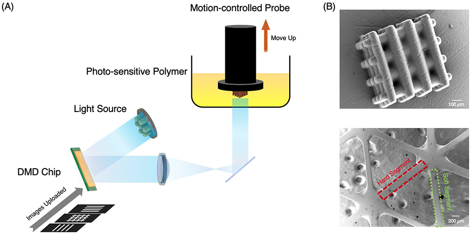
(A) Schematic of the DLP-based 3D printing process. A structure is first designed using computer aided-design (CAD) software, and digitally sliced along the z-direction into a series of images. These images were continuously uploaded onto the DMD chip while the 405 nm light is projected onto it and reflected onto a motion-controlled probe immersed in photo-sensitive polymer resin. The probe moved upwards while the light pattern changed based on the series of uploaded images. After printing, the printed structure was washed by isopropanol and water. (B) SEM images a log-pile structure made up by rods with a diameter of 75 μm (top) and a double network structure made by hard and soft segments with the same dimensions but different material properties (bottom).
2.3. Mechanical Properties of PGSA/PEGDA Resin
PGSA and PEGDA resins were used to make a molecular-scale double network where the main component PGSA enhances the elasticity, while the PEGDA enhances the mechanical strength of the final structure. Our previous work has demonstrated printing of PEGDA with high resolution and strength. [22] Thus, PEGDA is chosen as an additional crosslinker to improve the mechanical strength as well as printing speed and resolution. To investigate how varying the concentration of PGSA and PEGDA in a polymer affected gross material properties of the resin, samples were prepared with PEGDA crosslinker concentrations of 1% (LoResin), 5% (MeResin), and 10% (HiResin). Each resin was printed into modified ASTM type IV tensile bars and tested following ASTM standards [34]. A significant effect of the exposure time and crosslinker concentration was found for all mechanical property assessments (p<0.0001). The tensile modulus and ultimate tensile strength of three resins was, as expected, lowest for LoResin (149.11 ± 5.52 kPa, 124.04 ± 12.31 kPa) and highest for HiResin (445.53±41.48 kPa, 211.87 ± 30.33 kPa), each with a 30s exposure time (Figure 3A, B). These differences are attributed to different compositions of the polymer network structure. The flexible PGSA polymer chains can move freely with respect to each other, providing a space for elongation of the polymers. The short-chain crosslinker PEGDA brings the PGSA polymer chains closer, while restricting the motion by forming tight network structures between them. A higher crosslinker density will further decrease the open volume for polymer chains to move. In the presence of large external forces, the PGSA polymer chains in HiResin have limited room to change their conformation and location. Thus, the chemical bonds of the backbone structure and crosslinker can withstand the force, resulting in a stiffer and stronger polymer. The restriction of PGSA polymer chains to move also reduces elongation before rupture, resulting in the lowest failure strain observed for the HiResin material (Figure 3C). Therefore, by changing the relative concentration of PGSA and PEGDA, the mechanical properties of the final polymer can be easily modulated.
Figure 3.
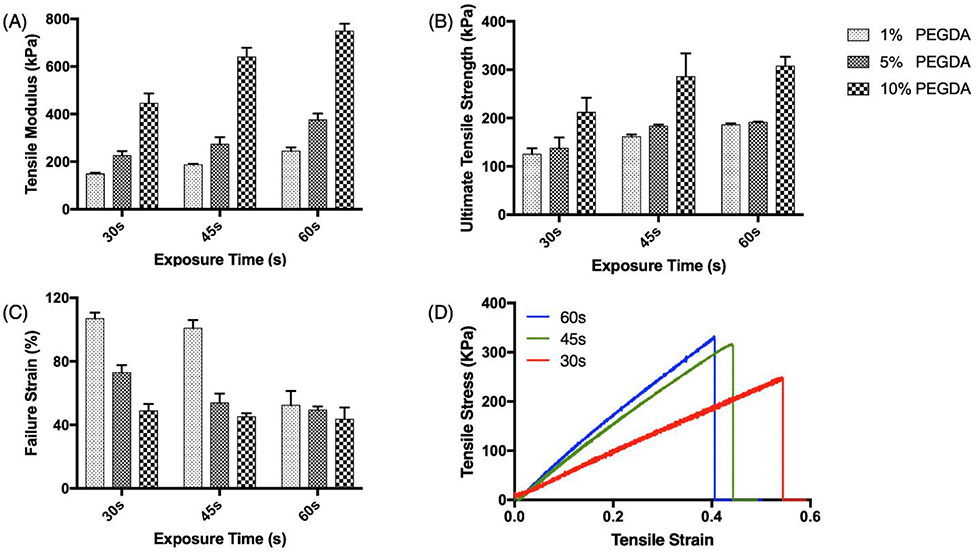
Intrinsic mechanical properties of PGSA made by different exposure times (x-axis) and PEGDA concentrations (filled pattern): (A) Tensile modulus, (B) Ultimate tensile strength, and (C) Failure strain. (D) Example stress-strain curves of tensile tests on samples printed with HiResin (10% PEGDA) with different light exposure times. The tensile modulus was calculated by the slope of the linear region of the stress-strain curve. The ultimate tensile strength was the highest stress the sample reached, and the failure strain was the largest strain the sample achieved before failure.
In addition to varying the composition of the polymer, the mechanical properties of the printed structure can also be tailored by varying the exposure time for printing, which is directly related to the degree of crosslinking [31]. In order to understand how the exposure time affects the material properties of the PGSA/PEGDA polymer, HiResin was printed with exposure times of 30s, 45s, and 60s, respectively. As expected, increasing the exposure time increased the tensile modulus and ultimate tensile strength of the polymer (Figure 3A, B). However longer exposure times also resulted in decreased failure strains, by up to 50.45% for the LoResin and 10.81% for the HiResin (Figure 3C). The effect of exposure time on the same resin formulation is demonstrated by the stress-strain curves of samples made by HiResin (Figure 3D). The intrinsic toughness is related to the polymer structure, thus all resin compositions under various exposure conditions have similar toughness, calculated by integrating the area under the stress-strain curves (Figure S5A). In LoResin, however, the long exposure time may cause the printed structure to become more brittle due to exhaustion of all available crosslinkers, resulting in a decrease of toughness.
2.4. HUVEC Viability
Previous studies have demonstrated that PGSA is biocompatible with fibroblasts and cardiomyocytes [32,35]. However, given its potential to be used for vascular patches and grafting, it is important to investigate the biocompatibility of PGSA with vascular endothelial cells. Testing of HUVEC cells on coated PGSA/PEGDA resins showed excellent viability (>90%) for all compositions of the PGSA/PEGDA composite at days 1, 3, and 7 after initial seeding (Figure 4, Supplementary Fig. 2).
Figure 4.
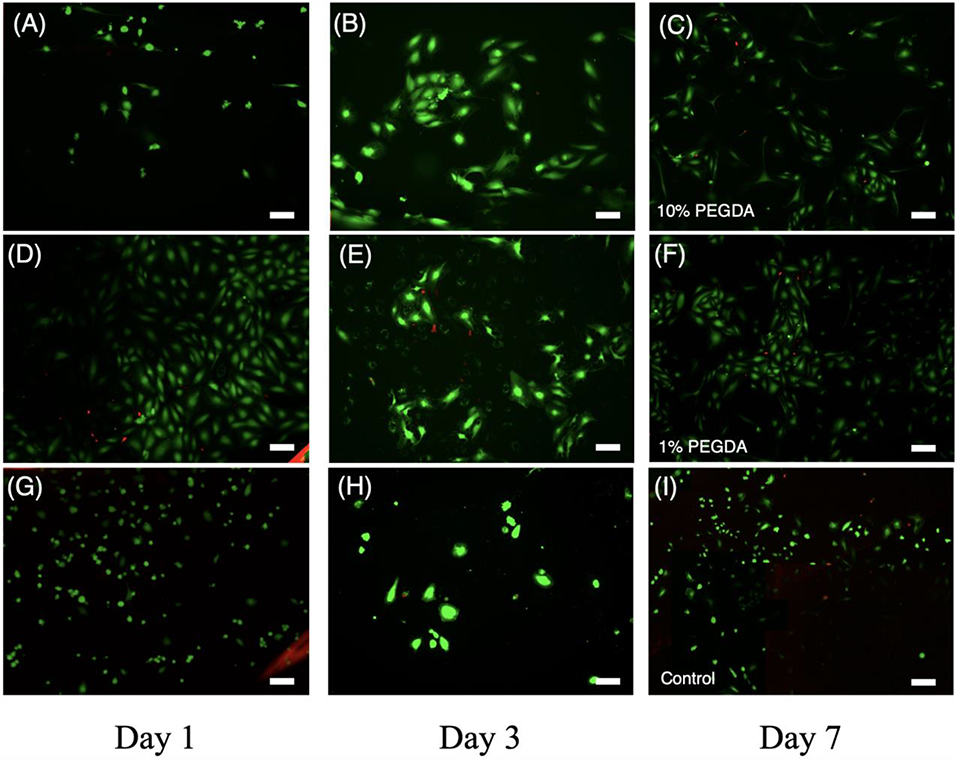
In vitro biocompatibility test of HUVEC cells seeded on printed PGSA disks. Calcein AM/ethidium homodimer staining of HUVEC cells seeded on HiResin (10% PEGDA) at (A) Day 1, (B) Day 3, and (C) Day 7; LoResin (1% PEGDA) at (D) Day 1, (E) Day 3, and (F) Day 7 and cover glass as a control at (G) Day 1, (H) Day 3, and (I) Day 7. Scale Bar = 100 μm
2.5. Finite element analysis of the DN structure
In order to optimize the mechanical properties of the DN structure, a FEA model was developed. By fitting the elastic modulus with different modulus ratios Es/Eh (Supplementary Figure 3), the elastic modulus of the network structure E can be determined from:
| (1) |
where Eh is the elastic modulus of the hard segments, Es is the elastic modulus of the soft segments, and is the relative density of the solid part (network porosity = ). A modulus ratio less than 1 implies that the modulus of DN is larger than that of soft SN but smaller than that of hard SN. Similar to other equations for predicting the mechanical properties of networks, equation 1 provides accurate predictions when [22].
2.6. Tensile Test of the DN Structure
Inspired by the toughening mechanism of interpenetrating networks (IPN) in nature, network structures with one exposure condition (single network, or SN) and two exposure conditions (double network, or DN) were printed using HiResin and tested (Figure 5, Figure 6B, D). SN structures with 30s exposure time had the lowest tensile modulus (11.91 ± 5.48 kPa), compared to the SN with 60s exposure time which had the highest (47.66 ± 10.14 kPa), and the DN structure’s tensile modulus was between the two SN structures (32.09 ± 4.36 kPa; Figure 5A). Furthermore, SN structures with 30s exposure time had the lowest ultimate tensile strength (5.92 ± 3.49 kPa), compared to the SN with 60s exposure time and DN which had similar ultimate tensile strength (SN: 14.11± 2.24 kPa; DN: 15.08 ± 5.10 kPa; Figure 5B). As expected, the failure strain was greatest in SN structures with the 30s exposure and the DN structure (SN: 62.58 ± 18.05 kPa; DN: 64.18 ± 9.02 kPa), and smallest in the SN structure with 60s exposure (43.31 ± 0.48 kPa, Figure 5C). However, the soft SN (30s) loses its linear stress-strain relationship above 0.55, likely due to irreversible structural damage to covalent bonds between polymers (Figure 5D). However, the DN still retains structural integrity up to a strain of 0.73 (Figure 5D).
Figure 5.
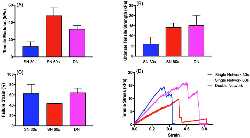
Mechanical properties of single (30s exposure - blue; 60s exposure – red) and double network (purple) structures: (A) tensile modulus, (B) ultimate tensile strength, and (C) failure strain. (D) Example stress-strain curve of tensile tests on different network structures.
Figure 6.
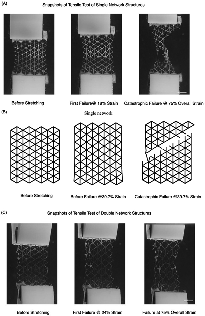
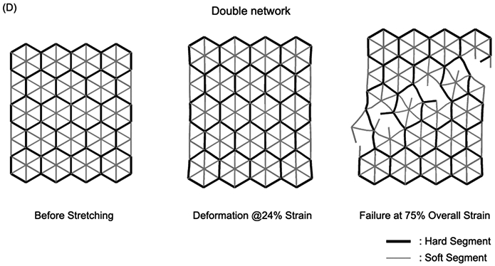
Mechanical testing of SN and DN structures. (A) Screenshots of a tensile test of a SN structure made with 60s exposure. At 18% strain, we observed an arm of the network rupture due to elongation. The global structure eventually failed at 40% strain. Note that at 30% strain, which is 75% of the overall strain before rupture, the network structure experienced a catastrophic failure where the strength decreased more than 80%. (B) Simulation of SN failure mechanism which features a 45° angle along the plane due to von Mises stress distribution. (C) Screenshots of tensile test of a DN structure made with 30s exposure for soft segments and 60s exposure for hard segments. The additional elongation provided by the soft segments increased the strain at which the first arm broke to 24%. The DN elongated to more than 70% before ultimate failure and at 75% of the overall strain the structure still retained more than 70% of its strength. (D) Simulation of DN structure failure mechanism. The presence of both hard and soft segments changed the failure mode and preserved the network structure. Scale bar = 1 cm.
2.7. Toughening Mechanics of the DN Structure
In the SN structures, beams sustain stretching deformation only (stretching-dominated structure; Figure 6A, B) and the failure path has an angle of inclination of 30° from the horizontal line [36]. In the DN structures, the soft beam sustains stretching deformation, but the stiff beam sustains bending deformation since the tensile modulus of the stiff beam is larger than the soft beam, resulting in large deflections but small overall stress (Figure 6C, D). As the dimensionless stress (ratio between stress and strength) of the soft beam is larger than that of the stiff beam, the stretched soft beams reach their fracture limit while the stiff beams are still below their fracture limit (Supplementary Figure 4). At 75% overall strain, the number of broken soft beams is three times the number of broken stiff beams, demonstrating that soft segments function as sacrificial beams to absorb energy before rupture in the DN structure.
Compared with the failure of the SN structure, the failure of the DN structure is controllable. Some of the soft beams break before any failure of the stiff beams, which dissipates energy in order to avoid catastrophic failure of the entire network. Thus, the unbroken stiff beams maintain the gross shape and function of the network structure and the overall toughness of the network structures can be improved by 100% (Figure S5B). Both simulation results and experimental results demonstrate that the failure strain of the DN before catastrophic fracture is larger than SN structures and bulk materials (Figure 5C, D).
3. Conclusion
In this study, we demonstrated how DN structures can be quickly fabricated out of a single polymer solution using DLP-based 3D printing. The mechanical properties of the 3D-printed resin were modulated by both controlling the different concentrations of the crosslinker and exposure times. The elastic modulus of the printed polymers ranged from 150 kPa to 800 kPa while the ultimate tensile strength ranged from 100 kPa to 300 kPa. All of the printed polymers could sustain more than 50% strain before failure and some combinations of crosslinker concentration and exposure time reached greater than 100% strain before failure, far exceeding other 3D printed polymers for biomedical applications. Furthermore, polymer-based DN structures were printed by allocating hard and soft segments in specific locations using different exposure times in a single shot. Such capability has not been demonstrated by any other fabrication technique. This structure demonstrated enhanced toughness by introducing soft sacrificial beams to absorb the energy during tensile testing while the hard segments maintained the overall shape of the structure. FEA models revealed the failure mechanism of network structures by optimizing the beam aspect ratios and strength ratios for the DN design. From this study, mechanically strong, biocompatible, and biodegradable elastomeric scaffolds can be designed and 3D printed for potential biomedical applications.
4. Methods
4.1. Materials
Triethylamine (TEA), Diphenyl (2,4,6-trimethylbenzoyl) phosphine oxide (TPO), anhydrous dichloromethane (DCM), D-chloroform (CDCl3) polyethylene glycol di-acrylate (PEGDA) with molecular weight of 700 Da and gelatin Type A from porcine skin were purchased from Millipore Sigma Aldrich (St. Louis, MO). Sebacic acid (SA), glycerol, 4-Dimethylaminopyridine (DMAP), Ethyl Acetate (EA) were purchased from Fisher Scientific (Waltham, MA). Acryloyl chloride (AC) was purchased from Alfa Aesar (Haverhill, MA). For cell culture and viability tests, Dulbecco’s Modified Eagle Medium (DMEM), fetal bovine serum (FBS) and penicillin/streptomycin (P/S) Calcein AM were purchased from Thermo Fisher Scientific (Waltham, MA). Ethidium Homodimer was purchased from Biotium (Hayward, CA).
4.2. Poly Glycerol Sebacate Synthesis
PGS was synthesized following a slightly modified previously reported protocol [8]. All glassware was pre-dried by heating 24 hours prior to initiating synthesis. SA and glycerol were mixed in a 1:1 molar ratio and melted at 140°C for 1 hour under argon gas. Polycondensation was conducted at 120°C in a three-necked round bottom glass flask with pressure reduced to 35 Pa. The reaction was continued for 15 hours while the pressure was maintained at 35 Pa with active pumping (Fig 1B).
4.3. Poly Glycerol Sebbacate Acrylate Synthesis
PGSA was synthesized following a slightly modified previously published protocol [32]. All of the containers used in the reaction were dried in an oven at 55°C prior to synthesis. 30 g of PGS was dissolved in 300 mL of DCM followed by 30 mg of DMAP. The reagents were cooled to 0°C under argon gas for 10 minutes before 7 mL of TEA was added dropwise. 3.3 mL of AC was added dropwise over a period of 5 min. The reaction was continued at room temperature for 24 hours. Then, DCM was removed by rotary evaporation at 40 °C and the remining solution was dissolved in EA to precipitate the excess TEA (Fig. 1B). The mixture was filtered, and the solute was collected, and further dried by rotary evaporation at 50°C at 5 Pa. The final product was stored at −20°C.
4.4. 1H NMR
1H nuclear magnetic resonance (1H NMR) spectra of the PGS and PGSA were measured (JEOL-500, Peabody , MA) and compared to confirm the chemical structure of the final products. Chemical shifts were referenced relative to the peak of CDCl3 at 7.26 ppm. The signal intensity of the methylene groups of sebacic acid (1.3 ppm) and the average of the acrylate groups (5.85 ppm, 6.15 ppm and 6.4 ppm) were used to calculate the degree of acrylation.
4.5. Mechanical Properties of PGSA/PEGDA Resins
The PGSA/PEGDA resins were prepared by adding PEGDA as crosslinkers with concentrations of 1% (LoResin), 5% (MeResin), and 10% (HiResin), respectively. 4% (w/v) of TPO was mixed with the resin solution as photoinitiator. The materials were printed into modified ASTM Type IV tensile bars under the same light intensity with different durations (30s, 45s, and 60s). Tensile tests were conducted on an Instron 5965 (Norwood, MA) with 10N load cell at a constant strain rate of 0.5% per second. The tensile modulus was determined by the slope of the stress-strain curve during elastic deformation. Additionally, the ultimate tensile strength and failure strain were assessed. Toughness was calculated by integrating the area under each stress-strain curve.
4.6. 3D Printing
The structures were printed by our continuous 3D printing system (Figure 2A). First, a 3D model was designed in Fusion360 (San Rafael, CA) and transformed into a series of 2D images in Matlab (Natick, MA) using custom software. These images were sequentially uploaded onto a digital micromirror device (DMD) chip (Texas Instruments, Dallas, TX) which projected 405 nm light into a PDMS coated reservoir containing the PEGDA/PGSA polymer. During printing, polymerized structures were covalently bound to a probe, which was slowly moved in the z-direction to accommodate continuous 3D printing. For each printing session, a fixed concentration of the resin was used to ensure homogeneity and integrity of the printed structures. The oxygen inhibition from PDMS prohibits the crosslinking of the resin to the reservoir. By changing the optic lens configurations, structures with 100-micron features on the centimeter scale were printed. The printed structure was removed from the build platform and washed using IPA before further examination by optical microscopy camera and SEM (Figure 2B).
4.7. Cell Viability Testing
Human umbilical vein endothelial cells (HUVEC) were purchased from ATCC (Manassas, VA) and cultured in Endothelial Cell Growth Medium 2 (EGM-2) from PromoCell (Heidelberg, Germany). The cells were used for seeding after 7-9 passages. The PGSA/PEGDA composite was printed into disks with diameter of 4 mm followed by coating with 2.5% gelatin solution for 30 minutes at 37°C. The disks were washed with PBS and immersed in growth media 1 day before cell seeding. At days 1, 3, and 7 post seeding, the disks were washed thoroughly with PBS and stained by calcein AM (Invitrogen ®, Carlsbad, CA) and ethidium homodimer-1 (Biotium, Fremont, CA) per manufacturer’s protocol. The cell viability was assessed via fluorescence microscopy (Leica DMI-6000, Wetzler, Germany) and ImageJ analysis.
4.8. Tensile Test of the Network Structures
Both the SN and DN structures were printed with HiResin. In order to test how the exposure time affects the elastic properties of the structure, SN structures were printed with exposure time of either 30s or 60s. To print the DN structure, a mask with the SN design was projected with 30s while another mask similar to the SN design but without diagonal beams was printed with 60s of exposure time, resulting in a structure with two exposure conditions penetrating each other (Figure 6D). The tensile tests were setup on Instron 5965 with the same test parameters as previous testing on ASTM type IV tensile bars. During the test, a video was recorded by Cannon EOS 80D to assess the rupture propagation, as well as to compare with the finite element analysis. The tensile modulus was determined by the slope of the stress-strain curve during elastic deformation and the failure strain was obtained by the final-fracture point of the curve. Toughness was calculated from the integral of the area under the curve.
4.9. Finite Element Simulation
The tensile behavior and failure process of DN structures made by HiResin was simulated using Abaqus (version 6.13, Dassault Systems, Rhode Island) combined with Python scripts. The geometry of the simulated network was identical to the geometry of the 3D printed structure. The material properties of the structure were assigned based on mechanical testing of the HiResin material (Table S1). Deformation of the structure was simulated under the same mechanical testing conditions as above. Simulations were performed until complete fracture of the model occurred.
4.10. Statistics
To compare the mechanical properties between resins with different compositions, a 3 x 3, two-way analysis of variance (ANOVA) (levels: PEGDA concentration, exposure time) with post hoc Sidak test was used for each exposure time (30s, 45s, 60s). All statistics were performed using Prism (Version 7.0a, La Jolla, CA). All data are reported as mean ± standard deviation.
Supplementary Material
Acknowledgements
This research was supported by National Institutes of Health (R21AR074763, R01EB021857, R33HD090662) and National Science Foundation (1937653, 1907434, 1903933). J.S. was supported by the National Science Foundation Graduate Research Fellowship Program under Grant No. DGE-1650112. We thank Joanne Hwang for her assistance in this work.
Footnotes
Supporting Information
Supporting Information is available from the Wiley Online Library or from the author.
Contributor Information
Pengrui Wang, Materials Science and Engineering Program, University of California San Diego, La Jolla, CA 92093.
David B. Berry, Department of NanoEngineering, University of California San Diego, La Jolla, CA 92093
Zhaoqiang Song, Department of Mechanical and Aerospace Engineering, University of California San Diego, La Jolla, CA 92093.
Wisarut Kiratitanaporn, Department of Bioengineering, University of California San Diego, La Jolla, CA 92093.
Jacob Schimelman, Department of NanoEngineering, University of California San Diego, La Jolla, CA 92093.
Amy Moran, Chemical Engineering Program, University of California San Diego, La Jolla, CA 92093.
Frank He, Department of Bioengineering, University of California San Diego, La Jolla, CA 92093.
Brian Xi, Chemical Engineering Program, University of California San Diego, La Jolla, CA 92093.
Shengqiang Cai, Department of Mechanical and Aerospace Engineering, Materials Science and Engineering Program, University of California San Diego, La Jolla, CA 92093.
Shaochen Chen, Department of NanoEngineering, Chemical Engineering Program, Materials Science and Engineering Program, Department of Bioengineering, University of California San Diego, La Jolla, CA 92093.
Reference:
- [1].Close RI, Physiol. Rev 1972, 52, 129. [DOI] [PubMed] [Google Scholar]
- [2].Lieber RL, Skeletal Muscle Structure, Function, and Plasticity., Lippincott Williams & Wilkins, 2002. [Google Scholar]
- [3].Hakim CH, Grange RW, Duan D, J. Appl. Physiol 2011, 110, 1656. [DOI] [PMC free article] [PubMed] [Google Scholar]
- [4].Lieber RL, Bodine-Fowler SC, Phys. Ther 1993, 73, 844. [DOI] [PubMed] [Google Scholar]
- [5].Yeh Y-C, Highley CB, Ouyang L, Burdick JA, Biofabrication 2016, 8, 045004. [DOI] [PubMed] [Google Scholar]
- [6].Zaky SH, Lee KW, Gao J, Jensen A, Verdelis K, Wang Y, Almarza AJ, Sfeir C, Acta Biomater. 2017, 54, 95. [DOI] [PubMed] [Google Scholar]
- [7].Singh D, Harding AJ, Albadawi E, Boissonade FM, Haycock JW, Claeyssens F, Acta Biomater. 2018, 78, 48. [DOI] [PubMed] [Google Scholar]
- [8].Wang Y, Ameer GA, Sheppard BJ, Langer R, Nat. Biotechnol 2002, 20, 602. [DOI] [PubMed] [Google Scholar]
- [9].Jeffries EM, Allen RA, Gao J, Pesce M, Wang Y, Acta Biomater. 2015, 18, 30. [DOI] [PMC free article] [PubMed] [Google Scholar]
- [10].Qazi TH, Rai R, Dippold D, Roether JE, Schubert DW, Rosellini E, Barbani N, Boccaccini AR, Acta Biomater. 2014, 10, 2434. [DOI] [PubMed] [Google Scholar]
- [11].Boutry CM, Kaizawa Y, Schroeder BC, Chortos A, Legrand A, Wang Z, Chang J, Fox P, Bao Z, Nat. Electron 2018, 1, 314. [Google Scholar]
- [12].Lee K-W, Wang Y, J. Vis. Exp 2011, 1. [DOI] [PMC free article] [PubMed] [Google Scholar]
- [13].Yang CH, Wang MX, Haider H, Yang JH, Sun JY, Chen YM, Zhou J, Suo Z, ACS Appl. Mater. Interfaces 2013, 5, 10418. [DOI] [PubMed] [Google Scholar]
- [14].Liu W, Deng C, McLaughlin CR, Fagerholm P, Lagali NS, Heyne B, Scaiano JC, Watsky M. a., Kato Y, Munger R, Shinozaki N, Li F, Griffith M, Biomaterials 2009, 30, 1551. [DOI] [PubMed] [Google Scholar]
- [15].Kausar A, in Asp. Polyurethanes, InTech, 2017. [Google Scholar]
- [16].Foster EM, Lensmeyer EE, Zhang B, Chakma P, Flum JA, Via JJ, Sparks JL, Konkolewicz D, ACS Macro Lett. 2017, 6, 495. [DOI] [PubMed] [Google Scholar]
- [17].Lee Seung-Mo, Pippel Eckhard, Ulrich Gösele Christian Dresbach, Qin Yong, Chandran C. Vinod, Bräuniger Thomas, Hause Gerd, Knez M, Science (80-. ). 2009, 324, 488. [DOI] [PubMed] [Google Scholar]
- [18].Chen F, Porter D, Vollrath F, Soc JR. Interface 2012, 9, 2299. [DOI] [PMC free article] [PubMed] [Google Scholar]
- [19].Sun J-Y, Zhao X, Illeperuma WRK, Chaudhuri O, Oh KH, Mooney DJ, Vlassak JJ, Suo Z, Nature 2012, 489, 133. [DOI] [PMC free article] [PubMed] [Google Scholar]
- [20].Chen Q, Zhu L, Chen H, Yan H, Huang L, Yang J, Zheng J, Adv. Funct. Mater 2015, 25, 1598. [Google Scholar]
- [21].Chen Q, Chen H, Zhu L, Zheng J, Macromol. Chem. Phys 2016, 217, 1022. [Google Scholar]
- [22].Zhu W, Li J, Leong YJ, Rozen I, Qu X, Dong R, Wu Z, Gao W, Chung PH, Wang J, Chen S, Adv. Mater 2015, 27, 4411. [DOI] [PMC free article] [PubMed] [Google Scholar]
- [23].Gou M, Qu X, Zhu W, Xiang M, Yang J, Zhang K, Wei Y, Chen S, Nat. Commun 2014, 5, 3774. [DOI] [PMC free article] [PubMed] [Google Scholar]
- [24].Zhu W, Qu X, Zhu J, Ma X, Patel S, Liu J, Wang P, Lai CSE, Gou M, Xu Y, Zhang K, Chen S, Biomaterials 2017, 124, 106. [DOI] [PMC free article] [PubMed] [Google Scholar]
- [25].Koffler J, Zhu W, Qu X, Platoshyn O, Dulin JN, Brock J, Graham L, Lu P, Sakamoto J, Marsala M, Chen S, Tuszynski MH, Nat. Med 2019, 25, DOI 10.1038/s41591-018-0296-z. [DOI] [PMC free article] [PubMed] [Google Scholar]
- [26].Soman P, Chung PH, Zhang AP, Chen S, Biotechnol. Bioeng. 2013, 110, 3038. [DOI] [PMC free article] [PubMed] [Google Scholar]
- [27].Soman P, Tobe BTD, Lee JW, Winquist AAM, Singec I, Vecchio KS, Snyder EY, Chen S, Biomed. Microdevices 2012, 14, 829. [DOI] [PMC free article] [PubMed] [Google Scholar]
- [28].Hribar KC, Soman P, Warner J, Chung P, Chen S, Lab Chip 2014, 14, 268. [DOI] [PubMed] [Google Scholar]
- [29].Qu X, Zhu W, Huang S, Li JY-S, Chien S, Zhang K, Chen S, Biomaterials 2013, 34, 9812. [DOI] [PMC free article] [PubMed] [Google Scholar]
- [30].Hribar KC, Choi YS, Ondeck M, Engler AJ, Chen S, Adv. Funct. Mater 2014, 24, 4922. [DOI] [PMC free article] [PubMed] [Google Scholar]
- [31].Pyo SH, Wang P, Hwang HH, Zhu W, Warner J, Chen S, ACS Appl. Mater. Interfaces 2017, 9, 836. [DOI] [PubMed] [Google Scholar]
- [32].Nijst CLE, Bruggeman JP, Karp JM, Ferreira L, Zumbuehl a, Bettinger CJ, Langer R, Biomacromolecules 2007, 8, 3067. [DOI] [PMC free article] [PubMed] [Google Scholar]
- [33].Ma X, Qu X, Zhu W, Li Y-S, Yuan S, Zhang H, Liu J, Wang P, Lai CSE, Zanella F, Feng G-S, Sheikh F, Chien S, Chen S, Proc. Natl. Acad. Sci 2016, 201524510. [DOI] [PMC free article] [PubMed] [Google Scholar]
- [34].ASTM International, 2017, DOI 10.1520/D5083-17. [DOI] [Google Scholar]
- [35].Gerecht S, Townsend SA, Pressler H, Zhu H, Nijst CLE, Bruggeman JP, Nichol JW, Langer R, Biomaterials 2007, 28, 4826. [DOI] [PubMed] [Google Scholar]
- [36].Lipperman F, Ryvkin M, Fuchs M, J. Mech. Mater. Struct 2009, 4, 441. [Google Scholar]
Associated Data
This section collects any data citations, data availability statements, or supplementary materials included in this article.


