Significance
We show a near–hysteresis-free piezoresistive sensor system from soft materials by using a method of generating unique three-dimensional nanoscale crack morphologies on metal-coated elastomeric microstructures. Our method addresses the major challenge of inherent electromechanical hysteresis faced by many electronic sensor skins using soft materials when large compressive pressures are applied. Piezoresistive sensors made from our flexible composite material track deformation with <3% hysteresis and can be reliably used as a healthcare wearable device for measuring pulse wave velocity on a small skin patch. We also showed that the low hysteresis enabled accurate and reliable single-touch classification of surface textures on textile surfaces for robotic applications.
Keywords: sensor, electronic skin, machine learning, robotics, wearable
Abstract
Electronic skins are essential for real-time health monitoring and tactile perception in robots. Although the use of soft elastomers and microstructures have improved the sensitivity and pressure-sensing range of tactile sensors, the intrinsic viscoelasticity of soft polymeric materials remains a long-standing challenge resulting in cyclic hysteresis. This causes sensor data variations between contact events that negatively impact the accuracy and reliability. Here, we introduce the Tactile Resistive Annularly Cracked E-Skin (TRACE) sensor to address the inherent trade-off between sensitivity and hysteresis in tactile sensors when using soft materials. We discovered that piezoresistive sensors made using an array of three-dimensional (3D) metallic annular cracks on polymeric microstructures possess high sensitivities (> 107 Ω ⋅ kPa−1), low hysteresis (2.99 ± 1.37%) over a wide pressure range (0–20 kPa), and fast response (400 Hz). We demonstrate that TRACE sensors can accurately detect and measure the pulse wave velocity (PWV) when skin mounted. Moreover, we show that these tactile sensors when arrayed enabled fast reliable one-touch surface texture classification with neuromorphic encoding and deep learning algorithms.
Human skin provides the body with continuous and distributed tactile feedback from the surrounding environment using an abundance of mechanoreceptors for reliable tactile perception (1). For example, the index finger has greater than 2,000 skin mechanoreceptors within ∼20 cm2 to intuitively obtain physical properties of objects such as shapes, hardness, and textures via touch interactions (2). Touch feedback enables applications in biomimetic electronic skins (e-skins) for real-time health-monitoring (3–5), human–machine interfaces (6, 7), robotics (8, 9), and neuroprosthetics (10, 11).
An ideal e-skin should possess high sensitivity, low hysteresis, and fast response. However, it also needs to be soft and conformable for versatile touch feedback across distinct objects. Although many pioneering efforts have been made to achieve these properties (12, 13), there remain challenges in achieving an optimal trade-off between sensitivity and hysteresis in soft-elastomer-based electronic skins due to the inherent viscoelasticity of the materials used.
This can be attributed to two main factors: 1) the irreversible frictional energy dissipation of polymer chains in the viscoelastic elastomers during cyclic deformation; and 2) the interfacial friction and adhesion between the sensory materials and electrodes, which continuously dissipates energy during deformations and contact (14, 15). Despite the use of micropyramidal elastomer designs that improve sensitivity and reduce hysteresis (16), such large deformation of elastomers inevitably leads to high energy dissipation, resulting in large cyclic hysteresis. For example, conductive polymers or piezoresistive polymer composites in piezoresistive sensors are highly sensitive, but they generally face severe hysteresis (6, 17–20).
Metal films possess superior electrical conductivity but small hysteresis as compared to the polymeric systems (12, 21, 22). However, when used as strain sensors, metal films typically sense very small tensile strains. For instance, flexible strain sensors incorporating cracked thin metal films on soft elastomeric substrates reported high sensitivity and low hysteresis, but the strain values measured were ∼2% (23, 24). This makes them unsuitable for large compressive strains often encountered in tactile electronic skin applications, such as in robotics and prosthetics.
Here, we present a piezoresistive pressure sensor with high sensitivity and low hysteresis, enabled by a unique morphology of metal films on soft micropyramidal elastomer. The sensors are capable of transducing large compressive pressure for the usage in health monitoring wearables and robotics tactile perception. To create this unique morphology, we developed a crack patterning technique, termed soft indentation process (SIP).
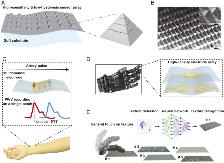
The SIP method created regular annular cracks in a metal thin film on micropyramidal elastomer structures (Fig. 1A). The methodology results in regular annular cracks (Fig. 1B). When used as piezoresistive compressive tactile sensors, they exhibited low hysteresis (2.99 ± 1.37%) and high sensitivities (> 107 Ω ⋅ kPa−1). We term this array of piezoresistive sensing microstructures as the Tactile Resistive Annularly Cracked E-Skin (TRACE).
Fig. 1.
Schematics of TRACE sensor and applications in health monitoring and robotics tactile perception. (A) Illustration of TRACE piezoresistive tactile sensing elements with 3D and regularly cracked bilayer micropyramids made of metal film and elastomer microstructure. (B) Scanning electron microscope (SEM) image of Pt-coated micropyramid array with controlled annular cracks. (C) Demonstration of local PWV measurement on a single-patch healthcare wearable by assembling TRACE on multichannel electrodes. (D) Illustration of TRACE sensor matrix on a prosthetic hand with a flexible sensor array. (E) Schematic of one-touch surface texture classifications.
We demonstrate some potential applications of TRACE sensors (Fig. 1 C–E). For example, a multielectrode TRACE sensor patch can accurately determine the local pulse wave velocities (PWV) on superficial blood vessels by tracking adjacent pressure values in a multiplexed fashion. In arrays close to the sensor density of the human fingertip, [i.e., 100 taxels (tactile pixels) cm−2], we were able to accurately detect and classify differences in textile surface textures using neuromorphic encoded outputs and deep-learning algorithms via a single-contact event (one-touch), as opposed to sliding or exploratory motions commonly used for texture detection (25, 26). We found that having near–hysteresis-free performance enabled an increase of 26.0% in classification accuracy when compared to piezoresistive sensors with large hysteresis. The combination of performance in high sensitivity and low hysteresis enables TRACE sensors to be versatile and useful in applications for health monitoring and robotics.
Design and Manufacturing of Annular Cracks
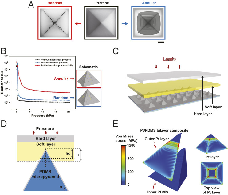
We first manufactured a bilayer structure comprising a thin platinum (Pt) film deposited on micropyramidal polydimethylsiloxane (PDMS) (SI Appendix, Methods and Fig. S1). Next, we proceeded to create the metal film crack morphology via compression. We found that crack onset (i.e., random or annular) depended significantly on the control of compression interface (Fig. 2A).
Fig. 2.
Mechanism of SIP method for regular annular cracks. (A) Comparison of random and controllable annular cracks of Pt film on micropyramid (Top view). The pristine Pt-film coating on micropyramid elastomer leads to the onset crack on the tips due to intensive stress concentration, propagating into uncontrollable random cracks with the increase of pressure. The proposed SIP method can generate regular and annular morphology cracks by rearranging stress distribution on bilayer micropyramid. (B) The optimized electromechanical property of the SIP method with annular cracks compared to random cracks. The annular cracks-induced gradual trend of piezoresistance is more suitable for a tactile sensor for a wide range of pressure, in comparison with sharp drops of resistance based on random cracks. (C) Schematic of SIP method for generating annular cracks of Pt film on micropyramid. (D) Theoretical model of SIP method for the design of stiff Pt film/PDMS bilayer micropyramid structure when applied compression force, where α, h, and hc are the sidewall angle of the pyramid, indentation depth, and the depth of the contact region, respectively. (E) FE simulation of stress-field distribution of bilayer microstructure by SIP method. The maximum stress occurs in annular fashion in a one-quarter model of bilayer structure (Left), and the stress distribution of Pt film on the surface (Right).
A direct compressive force on the bilayer led to a random onset cracking of the metal film. Using finite-element (FE) simulations, we found that the applied stress was concentrated at the tip of the micropyramid during compression, thereby initiating cracks along the ridges of the micropyramid. This resulted in random crack propagations (SI Appendix, Fig. S2). However, random cracks are not desirable because they detrimentally impact the performance of the piezoresistive tactile sensors by resulting in sudden resistance drops as compressive pressure is applied. Random onset cracks, especially those along the direction of pyramidal ridges, contribute minimally to the overall resistance change of the bilayer (Fig. 2B). This is because the direction of cracks is critical in determining the electrical pathways of currents, hence affecting the sensor’s pressure response.
Surprisingly, indenting the bilayer via SIP technique resulted in regular and annular crack morphologies on the micropyramid surface. This led to a gradual change of resistance over a wide pressure range (0–20 kPa) (Fig. 2B). The SIP compression technique was done by using a soft low-tack adhesive (mechanical modulus ∼1 MPa) to prevent crack initialization from the pyramid tip (Fig. 2C).
We analyzed the mechanical principle behind the SIP method using the theory of contact mechanics (SI Appendix, Methods). The mechanical model of SIP can be regarded as an indentation of a soft layer by a stiff micropyramidal Pt/PDMS indenter (Fig. 2D). Each pristine Pt-coated micropyramid was indented into the soft layer by a small compressive force. According to the theoretical formulation (SI Appendix, Methods), the indentation depth varied with Young’s modulus of this soft layer and the compressive force (SI Appendix, Fig. S3). The indentation depth of the micropyramid increased with the applied pressure, and it increased the area of micropyramid vertex coverd by the soft layer. Thus, cracks propagated with the applied pressure.
We further analyzed the stress-field distribution of Pt/PDMS bilayer microstructure in SIP (Fig. 2E). The FE simulations showed that the SIP method transferred the concentrated stress at the pyramid tip to annularly distributed stress on the surface. Most of the mechanical stress concentrated on the Pt layer, while the stress within the PDMS layer is minimal. This is due to the large ratio of Young’s modulus (>104) between the thin metal film and the PDMS elastomer. The regular annular three-dimensional (3D) metal cracks formed through the SIP technique enabled the piezoresistive sensing mechanism of the TRACE sensors.
Sensing Mechanism
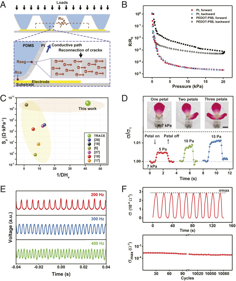
To elucidate the piezoresistive sensing mechanism of controlled annular cracks on micropyramids, we swept the voltage and measured the current of TRACE sensor under compressive loads (SI Appendix, Methods and Fig. S4A). The linear I-V relationship indicates the contact resistance as the sensing mechanism of the TRACE sensor. The pressure-induced contact resistance change originates from two synergistic effects: 1) reconnection of neighboring metal-film segments (Fig. 3A), and 2) increased contact area between electrodes and micropyramids (SI Appendix, Fig. S4B). Both effects decrease the resistance when the compression force increases.
Fig. 3.
Piezoresistive response of TRACE sensor. (A) The schematic model of the conductive pathways of TRACE sensor under compressing loads. (B) The pressure-induced electrical performance of TRACE sensor, compared with the PEDOT:PSS-coated micropyramid sensor. (C) Benchmark of TRACE sensor with both sensitivity and hysteresis being considered. We used Sp/DHe as an indicator to simultaneously evaluate sensitivity and hysteresis of resistive-type sensors, where Sp represents the peak sensitivity, and DHe is the degree of hysteresis, respectively. The smaller DHe (or namely, larger 1/DHe) means a lower hysteresis observed for the piezoresistive sensor, indicating more accurate and repeatable sensing performance of TRACE sensor. Yellow region: low hysteresis; orange region: high sensitivity. (D) The ability of TRACE sensor to detect a small pressure of a floribunda petal under the preload of 7 kPa, where σ1 is the conductance of the preload pressure of 7 kPa, respectively, where the black scale bar is 10 mm. (E) The output voltage of TRACE sensor under different frequencies when applied pressure. (F) Cyclic testing of TRACE sensor: time-resolved performance of successive 10 cycles (Top) and maximum conductivity change over 10,000 cycles (Bottom).
To describe the overall resistance change of the TRACE sensor, we defined Rseg as the resistance between two adjacent electrodes from the connection of metal segments for each micropyramid, which is a function of the applied pressure (P) and the number of annular segments (Ns). Then, we defined Rca as the resistance from the change of the contact area, which depends on the applied pressure (P). The unit resistance between two adjacent electrodes, defined as Ru, can be described through the series connection of Rseg and Rca (Ru = Rseg + Rca) (Fig. 3A). The parallel connections of each unit between the micropyramids array and electrodes result in the change of Ru, leading to the piezoresistive effect of the TRACE sensor.
Sensor Performance
To characterize the electrical performance, a pressure of 0–20 kPa was applied to the TRACE sensor at a strain rate of 5 μm/s. The resistance decreased continuously from the order of 108 Ω to 103 Ω (SI Appendix, Fig. S5A). We compared our results with an array of poly(3,4-ethylenedioxythiophene)-poly(styrenesulfonate) (PEDOT:PSS)-coated micropyramids (27) and the TRACE sensor exhibited a higher sensitivity over a broad pressure range (0–20 kPa) (Fig. 3B). Even at high-pressure loads, we observed a continuous decrease in resistance (SI Appendix, Fig. S5B).
We defined the sensitivity of the TRACE sensor by differentiating the resistance-pressure curve. When the pressure increased from 0 to 20 kPa, the sensitivity changed from the order of 109 Ω ∙ kPa−1 to 102 Ω ∙ kPa−1 (SI Appendix, Fig. S5C). Next, we defined the degree of electromechanical hysteresis, DHe, as the ratio of area difference between loading and unloading cycle of the resistance–pressure curve. The TRACE sensor showed a very low hysteresis (DHe = 2.99 ± 1.37%, among 5 samples) in the loading/unloading cycle (Fig. 3B and SI Appendix, Fig. S5 D and E). In comparison, PEDOT:PSS-coated sensor showed a high hysteresis (DHe = 73.90 ± 4.84%, among 5 samples) due to the inherent properties of viscoelastic polymers and the friction (14, 15).
These viscoelastic interfaces dissipate energy during loading/unloading cycles, resulting in a high DHe. However, the influence of the viscoelastic property of PDMS on DHe of TRACE sensor is minimal, although PDMS itself has a large mechanical hysteresis (28). This is because the conductance of the sensor depends solely on the contact between the outer Pt film and electrodes. Thus, controlling the crack patterns on elastic metal film effectively suppresses the viscoelastic effect in soft polymers. To compare with other state-of-the-art piezoresistive sensors (6, 17–19, 27, 29), we proposed a figure of merit: Sp/DHe, to simultaneously capture sensitivity and hysteresis of these sensors (SI Appendix, Methods). TRACE sensor possesses both high sensitivity and a huge reduction of hysteresis (Fig. 3C).
TRACE sensor is responsive to small pressures even under a relatively high preload of 7 kPa. We showed that we could detect consecutive additions of a floribunda petal ≈ 5 Pa (Fig. 3D). The sensor is also able to respond to the pressures quickly, with a fast response time of 1.6 ms (SI Appendix, Fig. S6). We also tested the response time of the TRACE sensor among five sample (3.52 ± 1.45 ms). To further characterize its pressure response, we generated vibrations with customized frequencies on the TRACE sensor with acoustic waves. The sensor is responsive to vibrational frequencies up to 400 Hz (Fig. 3E), which is comparable to the ability of human skins (10).
To demonstrate the durability of the TRACE sensor, we applied cyclic loads on the sensor and measured the maximum conductance σmax (σ = 1/R) at 20 kPa. The TRACE sensor exhibited reversible behavior and stable σmax over 10 cycles (Fig. 3 F, Top). After 10,000 cycles of cyclic loading, σmax remained steady over the next 100 cycles (Fig. 3 F, Bottom). The maximum deviation of resistance at 20 kPa over 10,000 cycles was within 2.4% (SI Appendix, Fig. S7).
Moreover, we investigated the batch-to-batch variations of TRACE sensor. We characterized sensor performance among five different samples (SI Appendix, Fig. S8A) and quantified the performance variation at specific pressures (SI Appendix, Fig. S8B). The presented SIP method can allow us to produce large-scale sensor films with repeatable pressure response. Pt thickness affects pressure response considerably. We characterized the performance of TRACE sensor with different sputtering time in SI Appendix, Fig. S9A. We also measured the relationship between sputtering time and deposition thickness (SI Appendix, Fig. S9B). The optimized Pt thickness (∼32 μm) from experiments results in high sensitivity, wide pressure range, and good stability of TRACE sensor to tactile stimuli. Inadequate or oversputtering of the Pt metal film resulted in a narrow pressure-sensitive range.
We also characterized the effect of micropyramid size on sensor pressure response in SI Appendix, Fig. S10A. The effect of size does not significantly affect the sensitivity. We also characterized the effect of micropyramid density on sensor pressure response in SI Appendix, Fig. S10B. Micropyramid array with lower structure density results in higher electromechanical sensitivity. Additionally, since the hysteresis of TRACE sensor is dominated by the elastic Pt layer, the change of PDMS micropyramid size or density does not significantly affect sensors’ hysteresis, as characterized in SI Appendix, Fig. S10C.
Human fingers bend with a radius of curvature of ∼10–20 mm. However, the bending of sensor film may result in parallel metal cracks on the PDMS substrate (24). We performed bending tests to investigate the influence of bending on crack generation and sensor performance. The cracks only happen when the bending curvature is very small (SI Appendix, Fig. S11A). We also performed cyclic bending using the motorized z-axis stage (Newmark) to bend TRACE sensor (bending radius of curvature: ∼16 mm) for 1,000 cycles (SI Appendix, Fig. S11B). To study the influence of potential parallel cracks from bending on compressive sensor performance, we applied specific pressures (2, 4, and 8 kPa) using weight on TRACE sensor and recorded sensor outputs at different bending cycles. The output remained steady over 1,000 cycles (SI Appendix, Fig. S11C). Thus, bending has minimal impact on sensing performance. Besides, we also characterized the effect of nonnormal pressure (SI Appendix, Methods and Fig. S12) and stretching (SI Appendix, Methods and Fig. S13) on the variation of sensor performance.
Superficial Pulse Wave Measurement and Pulse Tracing
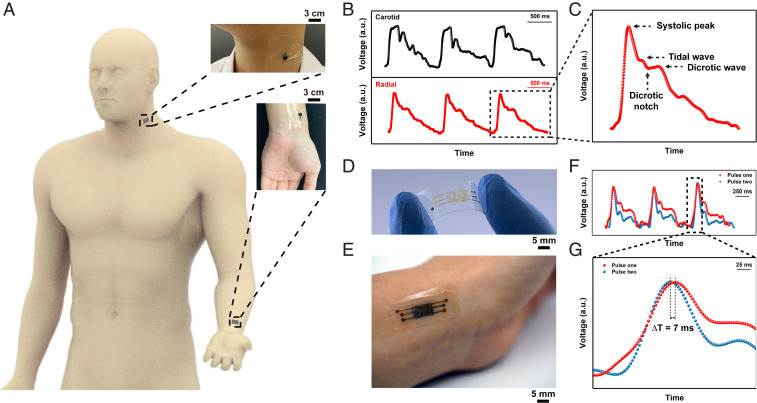
The TRACE sensor exhibits a large pressure sensitivity window with low hysteresis and fast response, showing potential to capture subtle physiological signals precisely. Hence, we demonstrated the ability of the TRACE sensor in arterial pulse measurements (Fig. 4A). The experiments on human subjects were approved under NUS-IRB N-19–097 with informed consent. By recording pulse waves at the superficial regions of the radial and carotid arteries simultaneously, we were able to continuously measure radial and carotid artery pulses (Fig. 4B). TRACE sensor is able to record the wave peak, notch, and its reflected waves (Fig. 4C) more accurately compared to a PEDOT:PSS sensor with large hysteresis (SI Appendix, Fig. S14A). Fast Fourier transform analysis also showed its higher responses to specific frequencies of artery pulses (SI Appendix, Fig. S14B). When attached to a robotic fingertip, TRACE sensors can measure radial arterial pulses on the wrists (Movie S1).
Fig. 4.
Superficial pulse measurement and pulse tracing. (A) The illustration of superficial pulse measurement located on the human neck and wrist. The zoom-in images show the photographs of the pulse measurement on a volunteer. (B) The graphs show results of the simultaneous pulse measurement at the carotid artery and radial artery, and (C) a zoom-in image showing the measurement result of one radial pulse. The specific peak and wave information are indicated. (D) The optical image of flexible electrodes with multiple channels. (E) The photograph showing localized pulse tracing by integrating TRACE sensor with multichannel electrodes. (F and G) The graphs showing the results of localized pulse measurement at the radial artery and pulse tracing.
These precise pulse waveforms recorded by TRACE sensor can further allow the PWV to be determined. The PWV is found to be significantly related to cardiovascular health, such as arterial stiffness and blood pressure (30, 31). Our TRACE sensor is able to trace the pulse transit time (PTT) via the fast and continuous measurement of arterial pulses at different spatial locations. The PWV can be acquired by dividing the distance between two arteries by the PTT (PWV = Distance/PTT). Specifically, the distance was calculated by the length difference between the heart-to-radial artery and the heart-to-carotid artery (∼75 cm). A PTT of 67 ms was determined using a trough-to-trough time difference (SI Appendix, Fig. S14C) (32). A PWV of ∼11 m/s was subsequently attained from carotid to radial artery, which is comparable to readings obtained in the literature (33).
We can also have a compact multielectrode TRACE sensor perform the PWV measurements from a localized arterial site by tracing the pulse at two regions spaced 4 mm apart proximal to the wrist radial artery (Fig. 4D and SI Appendix, Fig. S14D). An optical image illustrates the TRACE sensor with multichannel electrodes attached to the radial artery (Fig. 4E). As the arterial pulse propagates through the electrodes, distinct pressure waves recorded from different electrode pads captured the time differences to determine the PTT value. Spatially proximal sites generated two different pulses (Fig. 4F) in time. The disparity of two pulses comes from the different amplitudes and timing of reflected waves at different sites, but both of them exhibited a recognizable pulse peak (34). PTT was then obtained through a peak-to-peak timing difference (Δt = 7 ms), and the PWV was calculated to be 0.6 m/s (Fig. 4G). The PWV measurement in such a compact wearable format indicates the potential for use in health monitoring applications.
High-Density Pressure Mapping and Tactile Detection
Sensing of distributional tactile information is an essential ability for human skin. For example, the high-density subcutaneous slow-adapting (SA) and fast-adapting (FA) receptors at human fingertips play the primary role in acquiring information (e.g., shape, hardness, texture) through the physical interactions with objects, sensing static pressure and dynamic pressure, respectively.
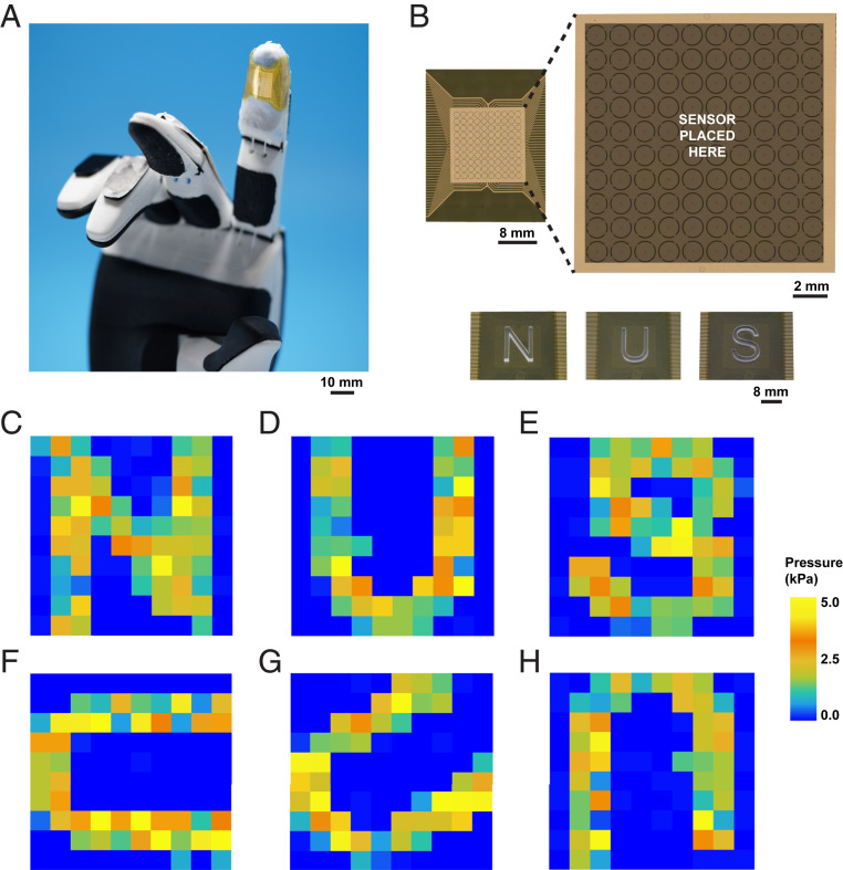
Inspired by the human hand, we designed an integrated sensor network to empower robot skins with the ability to detect distributional information of external stimuli. Specifically, we integrated a 100 taxels per cm−2 TRACE sensing matrix attached to fingertips as robot skins to mimic the functions of SA and FA receptors with high resolution (Fig. 5A). A multilayer 10-µm flexible polyimide substrate (Fig. 5 B, Top) with electrodes act as read-out connections for the sensing units. The top layer of the substrate comprises a 100-electrode (sensing unit) array and a common electrode. The center-to-center spacing between adjacent electrode pads is 1 mm, which is close to the distribution density of SA receptors (∼70 units per cm−2) or FA receptors (∼140 units per cm−2) underneath human fingertips (35, 36). The wires to read-out circuits are arranged on the bottom polyimide film and connected to the top layer electrodes through via holes (SI Appendix, Methods). The TRACE sensor layer bridges the sensing units and the common electrodes and modulates the electrical resistance when pressure was applied.
Fig. 5.
High-density pressure distribution mapping on a robotic hand. (A) Images of conformable electrodes of TRACE-SA/FA sensor matrix attached to the index fingertip of a robot hand. (B) Design of electrodes (10 × 10) of sensor matrix, and laser-cut N, U, and S letters were touching TRACE-SA sensor matrix. (C–H) The pressure distribution map of TRACE-SA sensor matrix touching N, U, and S letters at different rotate angles.
A neuromorphic asynchronously coded electronic skin (11) (ACES) ultrafast signaling technique generated the two tactile signal encodings: SA mode (TRACE-SA sensor) and FA mode (TRACE-FA sensor). TRACE-SA sensor transmits the resistance value of each electrode pad via a 1-ms pulse signature. The event frequency represents the value of the resistance and, thus, the intensity of the pressure. We imprinted laser-cut acrylic pieces with patterns of “N,” “U,” and “S” letters on the sensor matrix (Fig. 5 B, Bottom), and the distribution of decoded event frequency clearly mapped the shape of the letters and the letter orientations (SI Appendix, Fig. S15 A–F). We were also able to calibrate the pressure response (SI Appendix, Fig. S15G) and generate a pressure distribution when the letters were imprinted (Fig. 5 C–H). We also tested the dynamic tactile response of TRACE-FA sensor (Movie S2). The morphology of the object (letter N) was clearly obtained in time when the pressure was applied, enabling the possibility of the precise feeling of touch for robotic skin.
Tactile Identification of Textures Using Deep Learning
Empowered with the sense of touch, machines such as robots can potentially recognize textures through tactile interactions. Such tactile feedback has enormous potential to improve the robot’s perception of the physical world beyond vision and auditory modalities. For instance, the texture often helps to manipulate and reveal the physical properties of objects.
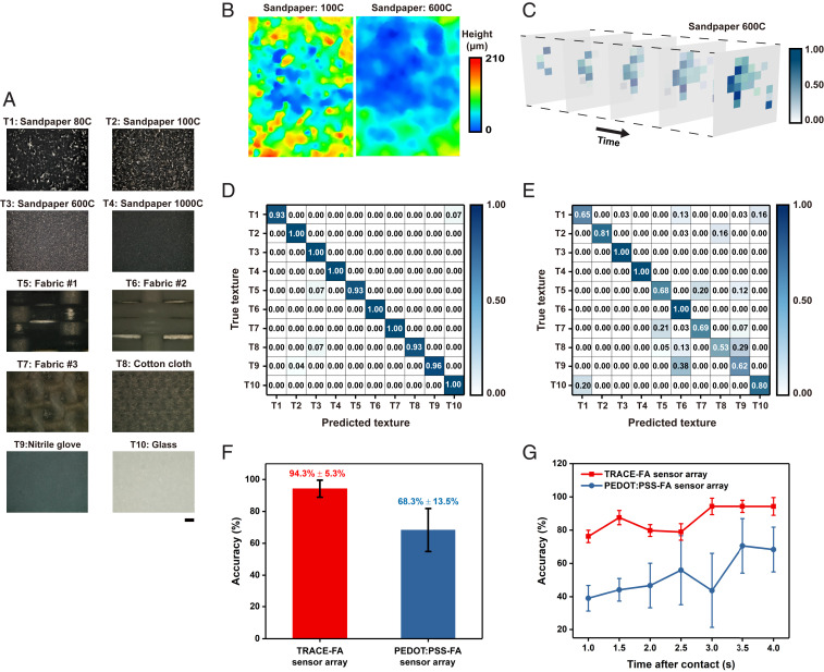
We demonstrate the performance of the TRACE sensor in tactile learning using surface texture classification. Using the 100-array TRACE-FA sensor, we constructed a tactile dataset by physically contacting (i.e., a contact force of ∼1 N) 10 different materials with different surface textures (Fig. 6A) (SI Appendix, Methods). Different materials have different surface textures, eliciting different responses and allowing classifications to be performed (Fig. 6B). With a single contact (one-touch) action, we formed the “tactile image” of TRACE-FA sensor array (Fig. 6C) by aggregating the pulse outputs. We then performed classification tasks using convolutional neural networks (CNNs) (Fig. 6D and SI Appendix, Methods).
Fig. 6.
Texture classification using deep learning. (A) Photographs of textures used in the classification task. (Scale bar, 200 μm.) (B) Examples of the corresponding surface profile measurements taken by a 3D optical profiler for sandpaper 100C and 600C. (C) The evolution of the tactile image of TRACE-FA sensor array over time for sandpaper 600C. (D and E) The confusion matrix of TRACE-FA and PEDOT:PSS-FA sensor arrays, respectively. (F) Average classification accuracy of the sensor arrays using CNNs. Error bars denote the standard derivation (SD). (G) Comparison of the classification accuracy achievable with various contact times. Error bars denote the SD.
For comparison, we constructed a similar tactile dataset with a 100-electrode sensor array using a PEDOT:PSS micropyramid sensor (27) on the ACES platform (PEDOT:PSS-FA) (Fig. 6E). We observed that classifying the textures with TRACE-FA sensor was ∼26.0% more accurate than the PEDOT:PSS-FA sensor (Fig. 6F). More importantly, the high SD of 13.5% for the latter indicates that there is a large variability in its tactile dataset, contributed by the high hysteresis of the PEDOT:PSS-FA sensor, especially affected when the time interval between trials is short. We observed a decrease in recognition performance when the contact time was reduced from 4 to 1 s (Fig. 6G). However, when using the TRACE-FA sensor, the classification accuracy was maintained at 76.2%. Our results highlight the importance of having a low-hysteresis and high-sensitivity sensor array for reliable tactile learning and sensing.
Conclusion
We introduced a piezoresistive tactile sensing element by using a SIP technique to achieve controllable 3D annular crack patterns on Pt films. The resulting piezoresistive tactile sensor has low hysteresis yet possesses a high sensitivity over a wide range of pressure. It can detect small pressures (5 Pa) even under a high preload (7 kPa). We performed a theoretical and numerical analysis to elucidate the stress distribution on metal/elastomer composite, revealing the mechanism and origins of annular cracks. When the TRACE sensor is mounted on skin, we can record arterial pulsations on superficial blood vessels noninvasively and measure the local PWV over a small skin region in a compact wearable form factor for hemodynamic monitoring. Furthermore, a 100-taxel per cm−2 TRACE sensor array can be combined with neuromorphic encoding methods for one-touch surface texture classification. With deep-learning algorithms, we can classify surface textures with much higher accuracies across different contact speeds. We anticipate that the TRACE sensors can be versatile e-skins for use in robotics and wearable devices.
Supplementary Material
Acknowledgments
B.C.K.T. acknowledges grant support from the Singapore National Research Fellowship (NRFF 2017-08), Singapore National Robotics Program Office (182 25 00053), Agency for Science Technology and Research A*STAR (A18A1B0045), and National University of Singapore (NUS) Start-up Grant 2017-01. We acknowledge facility and grant support from Institute for Health Innovation and Technology and the N.1 Institute for Health, NUS. H.Y. acknowledges the support from the NUS Research Scholarship.
Footnotes
The authors declare no competing interest.
This article is a PNAS Direct Submission.
This article contains supporting information online at https://www.pnas.org/lookup/suppl/doi:10.1073/pnas.2010989117/-/DCSupplemental.
Data Availability.
All data needed to evaluate the conclusions in this paper are present in the paper or the SI Appendix, Materials. Data on the texture classification are made available at https://doi.org/10.25540/BJ1B-0H3K.
References
- 1.Gardner Esther P, “Touch” in Encyclopedia of Life Sciences (ELS), (John Wiley & Sons, Ltd, Chichester, 2010), 10.1002/9780470015902.a0000219.pub2. [DOI] [Google Scholar]
- 2.Taube Navaraj W. et al., Nanowire FET based neural element for robotic tactile sensing skin. Front. Neurosci. 11, 501 (2017). [DOI] [PMC free article] [PubMed] [Google Scholar]
- 3.Kim D.-H. et al., Epidermal electronics. Science 333, 838–843 (2011). [DOI] [PubMed] [Google Scholar]
- 4.Niu S. et al., A wireless body area sensor network based on stretchable passive tags. Nat. Electron. 2, 361–368 (2019). [Google Scholar]
- 5.Boutry C. M. et al., A stretchable and biodegradable strain and pressure sensor for orthopaedic application. Nat. Electron. 1, 314–321 (2018). [Google Scholar]
- 6.Tee B. C.-K. et al., A skin-inspired organic digital mechanoreceptor. Science 350, 313–316 (2015). [DOI] [PubMed] [Google Scholar]
- 7.Huang Y. C. et al., Sensitive pressure sensors based on conductive microstructured air-gap gates and two-dimensional semiconductor transistors. Nat. Electron. 3, 59–69 (2020). [Google Scholar]
- 8.Boutry C. M. et al., A hierarchically patterned, bioinspired e-skin able to detect the direction of applied pressure for robotics. Sci. Robot. 3, 1–10 (2018). [DOI] [PubMed] [Google Scholar]
- 9.Han M. et al., Three-dimensional piezoelectric polymer microsystems for vibrational energy harvesting, robotic interfaces and biomedical implants. Nat. Electron. 2, 26–35 (2019). [Google Scholar]
- 10.Chortos A., Liu J., Bao Z., Pursuing prosthetic electronic skin. Nat. Mater. 15, 937–950 (2016). [DOI] [PubMed] [Google Scholar]
- 11.Lee W. W. et al., A neuro-inspired artificial peripheral nervous system for scalable electronic skins. Sci. Robot. 4, eaax2198 (2019). [DOI] [PubMed] [Google Scholar]
- 12.Hammock M. L., Chortos A., Tee B. C. K., Tok J. B. H., Bao Z., 25th anniversary article: The evolution of electronic skin (e-skin): a brief history, design considerations, and recent progress. Adv. Mater. 25, 5997–6038 (2013). [DOI] [PubMed] [Google Scholar]
- 13.Tee B. C. K., Mannsfeld C. B., Bao Z., “Elastomer-based pressure and strain sensors” in Stretchable Electronics, Someya T, Ed. (Wiley-VCH Verlag & Co. KGaA, 2012), pp. 325–353. [Google Scholar]
- 14.Jin L. et al., Microstructural origin of resistance-strain hysteresis in carbon nanotube thin film conductors. Proc. Natl. Acad. Sci. U.S.A. 115, 1986–1991 (2018). [DOI] [PMC free article] [PubMed] [Google Scholar]
- 15.Lipomi D. J. et al., Skin-like pressure and strain sensors based on transparent elastic films of carbon nanotubes. Nat. Nanotechnol. 6, 788–792 (2011). [DOI] [PubMed] [Google Scholar]
- 16.Mannsfeld S. C. B. et al., Highly sensitive flexible pressure sensors with microstructured rubber dielectric layers. Nat. Mater. 9, 859–864 (2010). [DOI] [PubMed] [Google Scholar]
- 17.Gong S. et al., A wearable and highly sensitive pressure sensor with ultrathin gold nanowires. Nat. Commun. 5, 3132 (2014). [DOI] [PubMed] [Google Scholar]
- 18.Pan L. et al., An ultra-sensitive resistive pressure sensor based on hollow-sphere microstructure induced elasticity in conducting polymer film. Nat. Commun. 5, 3002 (2014). [DOI] [PubMed] [Google Scholar]
- 19.Pang C. et al., A flexible and highly sensitive strain-gauge sensor using reversible interlocking of nanofibres. Nat. Mater. 11, 795–801 (2012). [DOI] [PubMed] [Google Scholar]
- 20.Luo N. et al., Flexible piezoresistive sensor patch enabling ultralow power cuffless blood pressure measurement. Adv. Funct. Mater. 26, 1178–1187 (2016). [Google Scholar]
- 21.Gao W., Ota H., Kiriya D., Takei K., Javey A., Flexible electronics toward wearable sensing. Acc. Chem. Res. 52, 523–533 (2019). [DOI] [PubMed] [Google Scholar]
- 22.Rogers J. A., Someya T., Huang Y., Materials and mechanics for stretchable electronics. Science 327, 1603–1607 (2010). [DOI] [PubMed] [Google Scholar]
- 23.Kang D. et al., Ultrasensitive mechanical crack-based sensor inspired by the spider sensory system. Nature 516, 222–226 (2014). [DOI] [PubMed] [Google Scholar]
- 24.Park B. et al., Dramatically enhanced mechanosensitivity and signal-to-noise ratio of nanoscale crack-based sensors: Effect of crack depth. Adv. Mater. 28, 8130–8137 (2016). [DOI] [PubMed] [Google Scholar]
- 25.Jamali N., Sammut C., Material classification by tactile sensing using surface textures. Proc. IEEE Int. Conf. Robot. Autom., 2336–2341 (2010). [Google Scholar]
- 26.Hanif N. H. H. M., Chappell P. H., Cranny A., White N. M., Surface texture detection with artificial fingers. Proc. Annu. Int. Conf. IEEE Eng. Med. Biol. Soc. EMBS, 8018–8021 (2015). [DOI] [PubMed] [Google Scholar]
- 27.Choong C. L. et al., Highly stretchable resistive pressure sensors using a conductive elastomeric composite on a micropyramid array. Adv. Mater. 26, 3451–3458 (2014). [DOI] [PubMed] [Google Scholar]
- 28.Kim T. K., Kim J. K., Jeong O. C., Measurement of nonlinear mechanical properties of PDMS elastomer. Microelectron. Eng. 88, 1982–1985 (2011). [Google Scholar]
- 29.Qiu L. et al., Ultrafast dynamic piezoresistive response of graphene-based cellular elastomers. Adv. Mater. 28, 194–200 (2016). [DOI] [PubMed] [Google Scholar]
- 30.Mitchell G. F. et al., Arterial stiffness and cardiovascular events: The Framingham Heart Study. Circulation 121, 505–511 (2010). [DOI] [PMC free article] [PubMed] [Google Scholar]
- 31.Laurent S. et al.; European Network for Non-invasive Investigation of Large Arteries , Expert consensus document on arterial stiffness: Methodological issues and clinical applications. Eur. Heart J. 27, 2588–2605 (2006). [DOI] [PubMed] [Google Scholar]
- 32.Millasseau S. C., Stewart A. D., Patel S. J., Redwood S. R., Chowienczyk P. J., Evaluation of carotid-femoral pulse wave velocity: Influence of timing algorithm and heart rate. Hypertension 45, 222–226 (2005). [DOI] [PubMed] [Google Scholar]
- 33.Koivistoinen T. et al., Pulse wave velocity reference values in healthy adults aged 26-75 years. Clin. Physiol. Funct. Imaging 27, 191–196 (2007). [DOI] [PubMed] [Google Scholar]
- 34.Boutouyrie P., Briet M., Collin C., Vermeersch S., Pannier B., Assessment of pulse wave velocity. Artery Res. 3, 3–8 (2009). [Google Scholar]
- 35.Johansson R. S., Flanagan J. R., Coding and use of tactile signals from the fingertips in object manipulation tasks. Nat. Rev. Neurosci. 10, 345–359 (2009). [DOI] [PubMed] [Google Scholar]
- 36.Johansson R. S., Vallbo A. B., Tactile sensibility in the human hand: Relative and absolute densities of four types of mechanoreceptive units in glabrous skin. J. Physiol. 286, 283–300 (1979). [DOI] [PMC free article] [PubMed] [Google Scholar]
Associated Data
This section collects any data citations, data availability statements, or supplementary materials included in this article.
Supplementary Materials
Data Availability Statement
All data needed to evaluate the conclusions in this paper are present in the paper or the SI Appendix, Materials. Data on the texture classification are made available at https://doi.org/10.25540/BJ1B-0H3K.


