Abstract
Knee pain is frequently seen in patients of all ages, with a wide range of possible aetiologies. Magnetic resonance imaging (MRI) of the knee is a common diagnostic examination performed for detecting and characterising acute and chronic internal derangement injuries of the knee and helps guide patient management. This article reviews the current clinical practice of MRI evaluation and interpretation of meniscal, ligamentous, cartilaginous, and synovial disorders within the knee that are commonly encountered.
Keywords: ligament, knee, magnetic resonance imaging, cartilage, meniscus, patellar instability
Introduction
Magnetic resonance imaging (MRI) of the knee is a common diagnostic examination that is performed for the detection and assessment of acute and chronic internal derangement injuries of the knee and serves as an important guide to patient management. Although radiography remains the standard initial imaging modality to diagnose knee derangement, MRI improves the evaluation of the bones and soft tissues. MRI is useful in the characterisation of meniscal, cruciate ligament, collateral ligament, and extensor mechanism injuries, as well as articular cartilage, synovial, and tendon disorders.
Technical considerations
There is wide variation of MRI systems, including open and closed bore magnet systems, various field strengths, and coil technologies, and MRI protocols such as pulse sequences and field-of-view are commonly customised for specific indications. These factors lead to great variability of pulse sequences utilised from institution to institution. A compromise between adequate signal-to-noise ratio (SNR), spatial resolution, and duration of the examination is needed to ensure that diagnostic quality images are acquired.
Although knee MRI can be performed on lower field strength systems, including open bore magnets, it is most commonly performed with either 1.5 or 3 Tesla (T) closed bore magnets. While both magnet strengths provide diagnostic images, 3T systems often have superior SNR and spatial resolution, which can help to improve diagnostic confidence and reduce scanning time. Moreover, advanced 3T imaging applications may help improve detection and characterisation of tumours and peripheral nerve disorders [1,2]. On the other hand, 1.5T imaging is useful to reduce metallic susceptibility artifacts from hardware or other metallic substances within the field of view, and some MRI-compatible medical devices may only be safe to image at 1.5T [3,4]. Regardless of magnetic field strength, dedicated knee coils will provide the best quality images.
MRI protocols of the knee commonly consist of three orthogonal imaging planes of section (axial, coronal, and sagittal), with a combination of fluid-sensitive sequences, either T2-weighted (T2W) fat-saturated (FS) or proton density-weighted (PDW) FS sequences, and T1-weighted (T1W) non-fat-saturated (NFS) imaging. Coronal and sagittal PDW sequences provide high SNR and spatial resolution and are more sensitive than T2W sequences for detecting meniscal pathology; most protocols will have at least one high-resolution PDW sequence in either the sagittal or coronal plane. T2W sequences may make bone and soft tissue oedema-like signal changes more conspicuous. Furthermore, they may be helpful to better characterise the postoperative meniscus. T1W images are usually performed without fat saturation and should be obtained to evaluate the bone marrow fat for marrow replacing processes or to detect fracture lines, while T1W FS images are obtained to detect gadolinium following intravenous or intra-articular contrast administration. Often, a dedicated cartilage sensitive sequence is also obtained (Table 1). For standard examinations, the American College of Radiology has guidelines for knee MRI parameters, including a maximum field-of-view of 16 cm, maximum slice thickness of 4 mm, maximum inter gap spacing of 50%, and a phase – frequency matrix of at least 192 × 256. With continued technical improvements in coil and magnet technology, many institutions utilise thinner slice thickness and greater in-plane resolution to improve visualisation of meniscal and articular cartilage structures while preserving adequate signal to noise within the time limits of an examination [5].
Table 1.
Routine non contrast enhanced 3T knee MRI protocol
| Sequence | TR (ms) | TE (ms) | Slice thickness (mm) | FOV (mm) |
|---|---|---|---|---|
| Sagittal PD FS | 3000 | 37 | 3.0 | 140 |
| Sagittal T1 FS | 600 | 17 | 3.0 | 140 |
| Coronal PD FS | 2990 | 37 | 3.0 | 140 |
| Axial PD FS | 5480 | 37 | 3.0 | 150 |
FOV – field of view, FS – fat-suppressed, PDW – proton density-weighted, TE – echo time, TR – repetition time
Intravenous contrast is not indicated for MRI of the knee performed for internal derangement, but is useful for the evaluation of synovitis, tumours, and infection. Intravenous contrast can be utilised to further evaluate atypical cysts and ganglia, and can occasionally be used to obtain an indirect arthrogram. Additionally, some institutions may use intravenous gadolinium to perform delayed gadolinium enhanced MRI of cartilage (dGEMRIC) imaging, which can help improve articular cartilage characterisation [6].
Magnetic resonance arthrography (MRA) is a technique in which dilute gadolinium or saline is injected intra-articularly to increase the conspicuity of meniscal and cartilage surface abnormalities. A wide variation in image-guided approaches to access the knee joint have been described. Within the knee, approximately 40 ml of a dilute gadolinium in normal saline solution is injected. A gadolinium dilution between 0.625 (1 : 800 dilution) and 1.25 (1 : 400 dilution) mmol/l achieves the greatest MRI T1 intensity [7]; however, some authors have achieved good results with dilutions up to 4 mmol/l [8]. Often, lidocaine, ropivacaine, or steroids are added to the mixture [9]. Bupivacaine has seen decreased intra-articular usage, due to some in-vitro studies demonstrating that it has higher cytotoxicity to chondrocytes at high concentrations [10].
MRA has been shown to be superior to MRI in the diagnosis of meniscal tears, but due to its relatively invasive nature, it is often reserved for particular indications, including assessment of meniscal tears following prior partial meniscectomy, and the evaluation of osteochondral injuries [8].
Meniscus
Normal anatomy and physiology
The menisci are crescent-shaped wedges of fibrocartilage located on the medial and lateral surfaces of the tibial plateau. Each meniscus is divided into an anterior horn, a body, and a posterior horn, and the anterior and posterior horns attach onto the central tibia via anterior and posterior meniscal roots, or root ligaments, respectively. They function to increase the stability of the knee joint, distribute axial load, absorb shock, and provide lubrication and nutrition to the joint [11,12]. Injuries to the menisci predispose patients to adjacent cartilage degeneration and osteoarthritis from increased axial and sheer stress [13]. Studies have shown that 50% of the medial compartment load and 70% of the lateral compartment load are transmitted through the menisci [11], and removal of the menisci increases contract stress by 100% in the medial compartment and between 200 and 300% in the lateral compartment [11,14].
The menisci are composed of fibrochondrocytes, water, primarily type I collagen, proteoglycans, and glycoproteins [11]. The collagen fibres are arranged in a circumferential pattern with interwoven radially oriented fibres to provide structural integrity [14]. The circumferential fibres provide the hoop strength to resist axial load and prevent extrusion of the meniscus [11]. In adults, the menisci are relatively avascular, with the medial, lateral, and middle geniculate arteries providing the blood flow [11]. In newborns, the peripheral 50% of the meniscus is vascularised (“red zone”) by the peripheral capillary plexus, whereas only 10-30% of the periphery of the meniscus is vascularised in adulthood, which may account for the increased intra-meniscal signal seen on MRIs of children [11].
The medial meniscus is broader in the anterior/posterior dimension than the lateral meniscus, which helps to better distribute the greater weight-bearing load in the medial compartment [11]. The posterior horn of the medial meniscus is also broader than the anterior horn, and the medial meniscus covers approximately 60% of the medial tibial plateau surface [11]. The anterior horn attaches to the anterior tibia near the intercondylar fossa, with some variability. It may attach to the anterior margin of the tibial eminence or just anterior to it [15,16]. The anterior root attachment loses the triangular shape of the meniscus itself and becomes flattened in cross-section as it approaches the tibial anterior intercondylar fossa. The transverse inter-meniscal ligament connects the anterior horns of the medial and lateral menisci and also stabilises the anterior horn, and there can also be a normal variant ligament that extends to the anterior cruciate ligament (ACL) [15,16]. The posterior horn attaches to the posterior intercondylar fossa between the lateral meniscus attachment and the posterior cruciate ligament (PCL) [11], and the posterior horn shape at the root may also lose its triangular appearance and become flattened or striated [15]. The posterior transverse intermeniscal ligament is rarely present and connects the posterior horns of the medial and lateral menisci [17].
The lateral meniscus covers approximately 80% of the lateral tibial plateau surface [11]. It is almost circular in shape with the anterior and posterior horns being nearly equivalent in size [11]. The anterior root attachment is located anterior to the intercondylar eminence and adjacent to the ACL [11]. It often has a prominent striated appearance caused by fibro-fatty tissue interposed between collagen fibres [18]. The posterior root attaches posterior to the lateral tibial eminence and anterior to the posterior horn of the medial meniscus root [11]. The posterior root attachment curves slightly cranial, and it is also oriented at a 45-degree angle with respect to the imaging coronal and sagittal planes. This causes relatively poor visualisation of root injuries due to magic angle artifact and oblique imaging plane orientation (Figures 1 and 2) [15,19].
Figure 1.
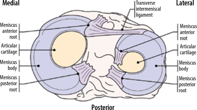
Meniscal anatomy. The medial meniscus is larger in the AP dimen- sion than the lateral meniscus. The posterior horn of the medial meniscus is also broader than the anterior horn of the medial meniscus. Relative inser- tion sites of the meniscal root attachments are shown
Figure 2.
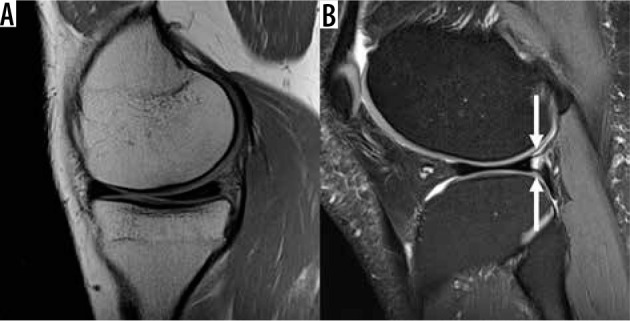
Normal medial and lateral menisci. A) Sagittal proton density- weighted (PDW) magnetic resonance (MR) image in a 41-year-old male with normal anterior and posterior horns of the medial meniscus. B) Sagit- tal PDW fat-saturated MR image in a 38-year-old female with normal anterior and posterior horns of the lateral meniscus, also demonstrating in- tact anteroinferior and posterosuperior popliteomeniscal fascicles (arrows)
Along with the transverse anterior inter-meniscal ligament, the lateral meniscus is stabilised by the anteroinferior, posterosuperior, and posteroinferior popliteomeniscal fascicles, which are located posterolaterally along the periphery of the lateral meniscal posterior horn [20]. The anteroinferior and posterosuperior fascicles form the popliteus hiatus, through which the popliteal tendon courses to become extra-articular (Figure 2). The meniscofemoral ligament is commonly seen and courses obliquely from the periphery of the lateral meniscal posterior horn and the lateral surface of the medial femoral condyle within the intercondylar notch; it is known as the ligament of Humphry if it occurs anterior to PCL, and the ligament of Wrisberg if it occurs posterior to PCL [12,15]. Another infrequently present anatomic variant is the oblique meniscomeniscal ligament that connects the anterior horn of one meniscus with the posterior horn of the other meniscus. If present, these ligaments extend obliquely through the intercondylar notch and can mimic a displaced meniscal tear. They are named by their anterior attachment side (i.e. the medial meniscomeniscal ligament connects the anterior horn of the medial meniscus with the posterior horn of the lateral meniscus) [17,21].
Given that the menisci are composed primarily of fibrocartilage, they are dark (either black or charcoal grey) on all pulse sequences. In patients younger than 40 years, they may have intermediate signal along the periphery related to vascularity, or contusion if there has been prior trauma. On the other hand, in older patients intrameniscal signal alteration that does not meet criteria for meniscal tear may be related to intrasubstance degeneration or contusion. In the coronal plane, each meniscus has a predictable isosceles triangular morphology with longer superior and inferior articular surfaces compared with the periphery. In the absence of prior meniscal surgery, meniscal morphology deviating from this predictable appearance is a direct sign of meniscal tearing. On sagittal imaging, the periphery of each meniscus has a bow tie or rectangular shape, known as the “bow tie” appearance, which indicates that the anterior and posterior horns are connected. As the sagittal images continue centrally the anterior and posterior horns normally separate from one another, resulting in distinct triangles [22].
Normal variants
The average length of the meniscus from the inner margin to the periphery is approximately 11-12 mm [23]. A discoid meniscus or incomplete discoid meniscus occurs when the meniscal length exceeds 14 mm [24], as the meniscal tissue extends farther centrally to cover more of the tibial plateau articular surface. Sequential sagittal images can also suggest a discoid meniscus if the meniscus maintains the rectangular or bow tie appearance on more than two consecutive sagittal images, if the slice thickness is 4 mm or more (“bow tie” sign). Lateral discoid menisci are much more common than medial discoid menisci (Figure 3) [12,15,25].
Figure 3.
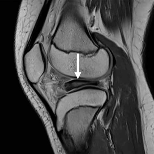
Discoid meniscus. Sagittal proton density-weighted magnetic resonance image in an 11-year-old female with a discoid lateral meniscus with extensive intrameniscal signal (arrow)
A ring lateral meniscus is a rare variant in which the meniscus forms a complete ring [15,26] and can mimic a displaced bucket handle tear. This can be differentiated from a tear by noting a normal triangular morphology of the meniscus with the absence of a donor site for the fragment [11,15].
Tears
Diagnosis of a meniscal tear includes linear intra-meniscal signal that contacts the superior or inferior articular surface of the meniscus or a defect in the normal shape of the meniscus (Figure 4) [12,15,26].
Figure 4.
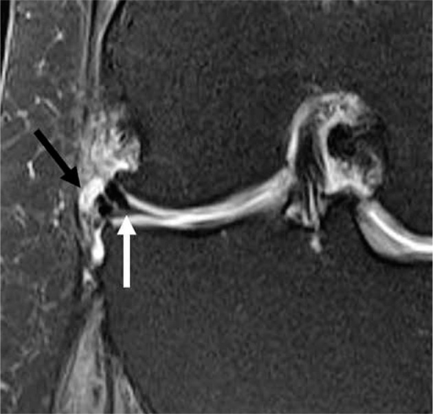
Meniscal tear, para-meniscal cyst. Coronal proton density-weighted fat-saturated magnetic resonance image in a 55-year-old female with small parameniscal cyst (black arrow) adjacent to the body of the lateral meniscus with an associated meniscal tear (white arrow)
Using arthroscopy as the gold standard, if an abnormal increased linear signal is identified on at least two images (two consecutive coronal or sagittal images, or one sagittal and one coronal at the same location), the positive predictive value (PPV) of a tear is 94% in the medial meniscus, and 96% in the lateral meniscus. If the abnormal signal touches the articular surface on only one image, the PPV of tear is 43% in the medial meniscus and 18% in the lateral meniscus [12,15,27,28]. If the abnormal signal only touches the articular surface on one image, the term probable or possible tear can be used. In contrast, increased signal that does not touch the surface is not associated with a tear [29], nor has it been shown to progress to a tear [30].
There are multiple secondary findings that are associated with meniscal tears.
A parameniscal cyst represents the peripheral leakage of joint fluid through a meniscal tear, typically horizontal in orientation (Figure 4) [31]. The presence of a parameniscal cyst has a PPV of tear of 90%, unless it is located adjacent to the anterior horn of the lateral meniscus, where the PPV of tear drops to 67% [15,32].
Meniscal extrusion greater than 3 mm beyond the peripheral margin of the tibial plateau has also been associated with meniscal tears. 76% of medial meniscus root tears have extrusion, and 39% of extrusions have medial root tears [33].
A meniscal ossicle has been shown to be associated with posterior horn medial meniscal root tears; one study demonstrated that meniscal ossicles occurred at the medial meniscus posterior root in 89% of cases, and the meniscus was torn in 98% of the cases (Figure 5) [34].
Figure 5.
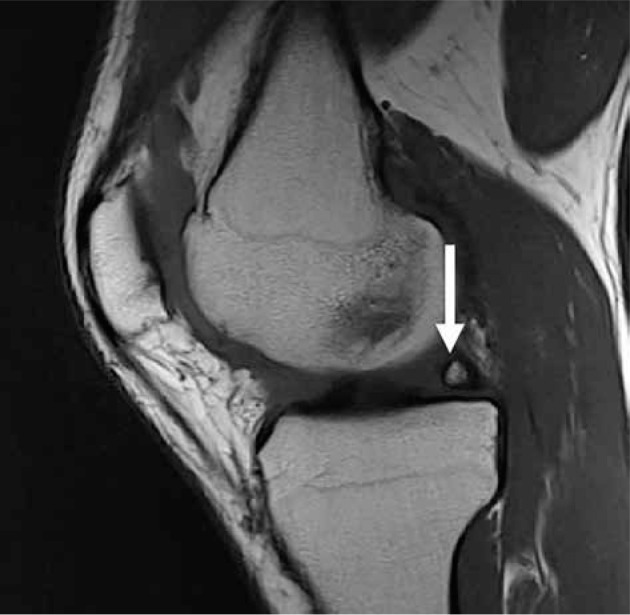
Meniscal ossicle. Sagittal proton density-weighted magnetic res- onance image in a 40-year-old male showing a meniscal ossicle (arrow) in the region of the posterior horn medial meniscal root
The anteroinferior or posterosuperior popliteomeniscal fascicles are seen in 97% of patients who have a normal lateral meniscus [15,20], and thus non-visualisation of the popliteomeniscal fascicles may increase the suspicion of an underlying lateral meniscal tear (Figure 2) [12]. The absence of the popliteomeniscal fascicles has also been reported in patients with symptomatic hypermobile lateral menisci. [35].
Linear subchondral bone marrow oedema-like signal intensity can be associated with both medial and lateral meniscus tears [15]. In the absence of prior partial meniscectomy, this finding can be helpful to improve diagnostic confidence in diagnosing a tear when other imaging findings are equivocal.
Tear description
Once a meniscal tear is identified, a description of the tear shape and the presence of any displaced meniscal fragments should be documented. Displaced fragments can cause a mechanical knee obstruction. Many different terminologies have been utilised to describe meniscal tears, without consensus. Common terms utilised to describe meniscal tears include horizontal, longitudinal vertical, and radial tears. Additional descriptive terms such as oblique, parrot beak, vertical flap, horizontal flap, meniscal root, and bucket handle tears are often utilised in reports and are usually displaced fragment variations of the horizontal, longitudinal vertical, and radial tears. Complex tears have more than one component and are often referred to as multidirectional tears.
The horizontal tear runs parallel/obliquely to the articular surface and contacts either the superior or inferior articulating surface of the meniscus or its inner free edge (Figures 4, 6 and 7) [12]. When these tears extend to one of the articular surfaces, they may also be called oblique tears. These tears are often degenerative and age-related, and are seen in the setting of osteoarthritis [12,36]. Parameniscal cysts are more commonly associated with horizontal tears [12,37] (Figure 4). Displaced horizontal tears are sometimes referred to as horizontal flap tears (Figures 8 and 9). Often, displaced meniscal fragments are identified posteriorly near the posterior cruciate ligament, into the intercondylar notch, or within the recesses between the collateral ligaments and the femur/tibia [38].
Figure 6.
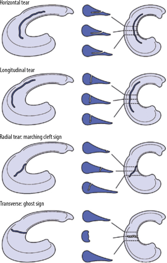
Horizontal, longitudinal, radial, and transverse tears. Horizontal, longitudinal, radial, and transverse tears depicted in three-dimensional and cross-sectional drawings
Figure 7.
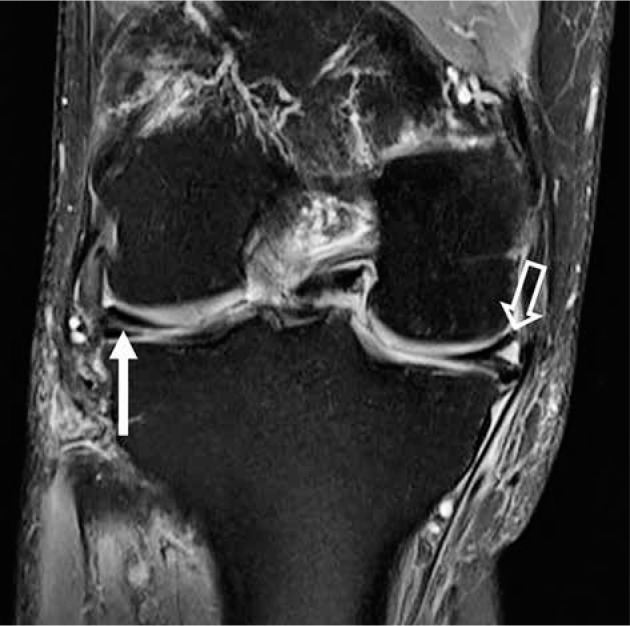
Horizontal meniscal tear. Coronal proton density-weighted fat- saturated magnetic resonance image in a 63-year-old female with linear intrameniscal signal (closed arrow) extending to the undersurface of the body of the lateral meniscus, consistent with tear. High signal (open arrow) in the contralateral, medial meniscus does not extend to the meniscal arti- cular surface and is consistent with mucoid degeneration
Figure 8.
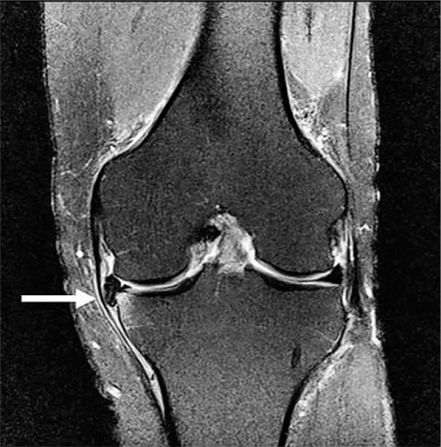
Horizontal meniscal tear with displaced fragment. Coronal proton densi- ty-weighted fat-saturated magnetic resonance image in a 53-year-old male with tear of the medial meniscus and displaced meniscal fragment/flap (arrow) locat- ed between the medial collateral ligament and the medial tibial plateau. There is subchondral bone marrow oedema-like signal in the adjacent tibia
Figure 9.
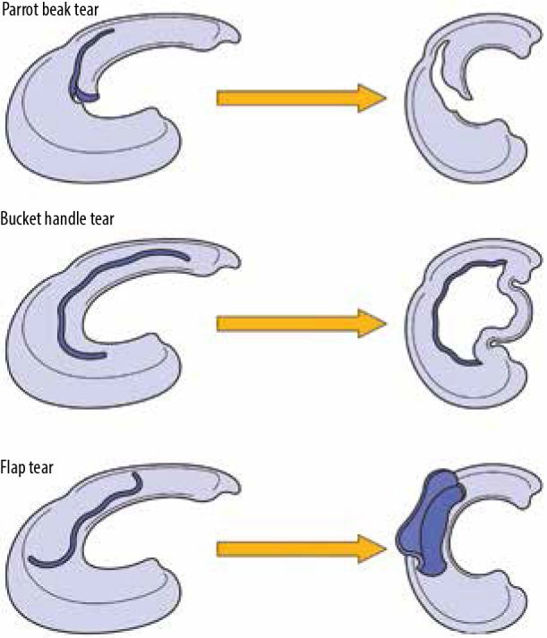
Meniscal tears with displaced fragments. Parrot beak, bucket han- dle, and flap tears in three-dimensional drawings
A longitudinal vertical tear runs perpendicular to the articular surface, along the longitudinally oriented fibres of the meniscus (Figure 10) [12]. These are usually traumatic and can be associated with ACL tears [12,39]. They tend to involve the peripheral red zone and occur in the posterior horn [12,40]. Nondisplaced tears occurring in the red zone are often treated with conservative management due to their increased propensity to heal. Displacement of a longitudinal vertical tear of the meniscus is known as a bucket handle tear, which more commonly occurs in the medial meniscus. The meniscal fragment often displaces into the intercondylar notch adjacent to the PCL, creating the appearance on sagittal imaging of a second PCL (“double PCL” sign) or adjacent to the anterior horn, creating the appearance of a second anterior horn (“double anterior horn” sign) (Figures 9 and 11).
Figure 10.
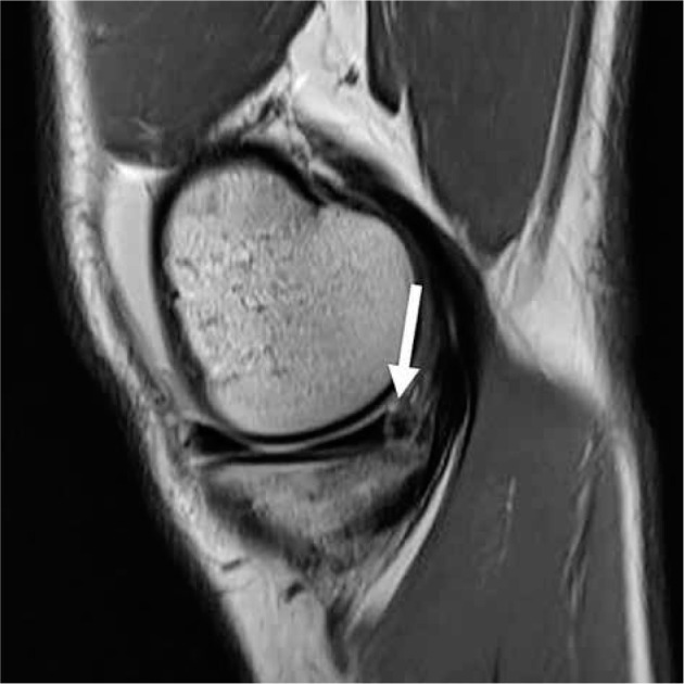
Longitudinal vertical tear. Sagittal proton density-weighted magnetic resonance image in a 27-year-old male with longitudinal vertical tear (arrow) in the posterior horn of the medial meniscus
Figure 11.
Displaced bucket handle tears. A) Sagittal and B) coronal proton density-weighted fat-saturated magnetic resonance images in a 34-year-old male with a bucket handle tear show a displaced meniscal fragment adjacent the posterior cruciate ligament (PCL) (white arrow), known as the “double PCL” sign, as well as a displaced meniscal fragment in the intercondylar notch (black arrow). C) Sagittal proton density-weighted fat-saturated magnetic resonance image in a 66-year-old male with a bucket handle tear shows the fragment displaced anteriorly (white arrow), adjacent the anterior horn, known as the “double anterior horn” sign
A radially oriented tear also runs perpendicular to the articular surfaces of the menisci [12]. However, these tears run along the meniscal short axis, perpendicular to the longitudinally oriented fibres of the meniscus (Figures 6 and 12). Radial tears disrupt the meniscal hoop strength, leading to loss of meniscal function and potential meniscal extrusion [11,12]. A radially oriented tear involving the posterior meniscal root is often referred to as a meniscal root tear or meniscal root avulsion (Figure 12) [12].
Figure 12.
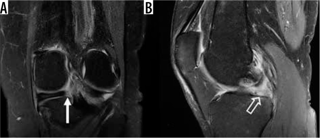
Radial tear of meniscal root. A) Coronal and B) sagittal proton density-weighted fat-saturated magnetic resonance images in a 65-year- old female with a radially oriented tear of the root of the medial meniscus, with an absent posterior meniscal root attachment (white arrow in A), cre- ating the “ghost meniscus” sign (open arrow in B)
Differentiating a radial tear from a longitudinal vertical tear on cross-sectional imaging can sometimes be difficult initially because both tears have a vertical component. The vertical component of a longitudinal vertical tear stays approximately equidistant from the periphery and inner free edge of the meniscus on multiple consecutive images. In a radial tear that is obliquely oriented to the imaging plane of section, the vertical defect will progress from the inner free edge of the meniscus on one image, to the peripheral aspect of the meniscus on sequential images (“marching cleft” sign) (Figure 13). If the tear orientation is purely in the sagittal or coronal plane, the meniscus will be absent on one or more images on that plane (“ghost meniscus” sign) and be present on adjacent images; and there will be a corresponding vertical defect on the orthogonal plane (Figures 6 and 12). A type of vertical tear that progresses obliquely from a radially oriented tear at the inner free edge of the meniscus to a longitudinally oriented tear closer to the periphery is often termed a “parrot beak” tear (Figure 13).
Figure 13.
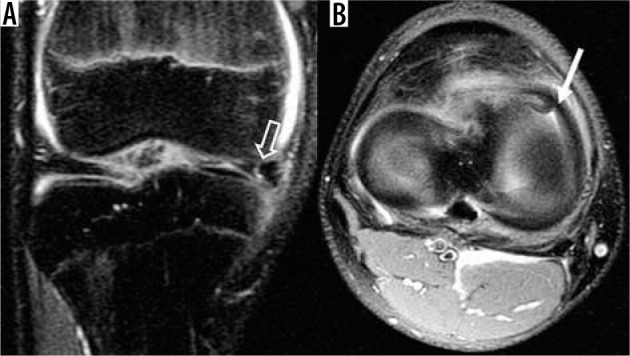
Parrot beak tear. A) Coronal and B) axial proton density-weight- ed fat-saturated magnetic resonance images show a vertical tear that progresses from a radially oriented tear (open arrow in A) at the anterior horn of the medial meniscus. This tear has a curved appearance similar to a parrot’s beak on axial images (white arrow in B)
Chondrocalcinosis, which represents the deposition of calcium crystals within the menisci or articular cartilage, can occasionally mimic a meniscal tear. Although chondrocalcinosis appears as dark-signal intensity on MRI in the articular cartilage, the chondrocalcinosis within the menisci often appears on MRI as a high signal intensity region on T1W, PDW, and short tau inversion recovery (STIR) sequences, which can decrease the sensitivity and specificity for the detection of meniscal tears [41].
Surgeons may perform partial meniscectomies, debridement of menisci, or direct repair of meniscal tears. The criteria for meniscal tear evaluation after surgery become difficult to apply as the post-surgical appearance of a meniscus overlaps with the criteria for diagnosing meniscal tears. When a partial meniscectomy is performed, signal abnormality that was originally intrasubstance within a meniscus may be converted into signal that touches the superior or inferior surface. The granulation tissue from a healing meniscal tear can also have similar signal characteristics to a tear. Therefore, the diagnosis of a residual or new meniscal tear in post-operative cases relies on the presence of either displaced meniscal fragments or parameniscal cysts, or the presence of fluid/gadolinium signal intensity extending into the meniscus (Figure 14) [8].
Figure 14.
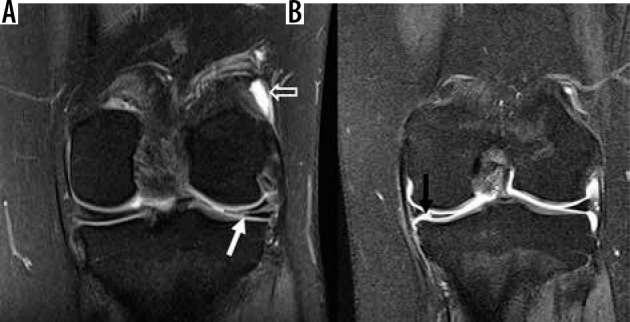
Magnetic resonance arthrography. A) Coronal T1 fat-saturat- ed magnetic resonance image post intra-articular contrast injection in an 18-year-old female with lateral meniscus linear signal that is intermedi- ate in signal intensity (white arrow), compared to bright contrast injected into joint space (open arrow), probably representing granulation tissue in a previously surgically repaired lateral meniscus. B) Coronal T1 fat-satu- rated magnetic resonance image post intra-articular contrast injection in a 19-year-old male demonstrating a contrast-bright intensity defect (black arrow) in the medial meniscus, representing a radial tear
Meniscal allograft transplantation (MAT) is a potential treatment option for meniscal deficiency. This treatment is reserved for young, symptomatic patients, and often those who are also undergoing ACL reconstruction or cartilage repair [42]. The 10-year survival rate for MAT is approximately 74% [42]. The meniscal graft is primarily secured through a tibial bone plug or via tibial tunnels. MRI can be utilised for postoperative assessment of MAT, to include evaluation for meniscal transplant fragmentation, degeneration, and extrusion (Figure 15) [43].
Figure 15.
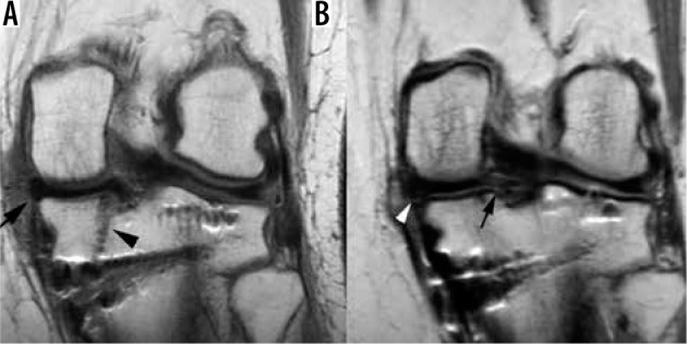
Meniscal transplant. Coronal proton density-weighted non-fat- saturated contrast enhanced magnetic resonance (MR) images in a 39-year-old female following medial meniscal transplant. A) Postoperative MR image taken 3 months after meniscal transplant shows the meniscal transplant (arrow) and the posterior tibial tunnel (arrowhead). B) MR image obtained two years later, after the patient started experiencing worsening medial knee pain, shows new tearing of the posterior root ligament (arrow) and heterogeneous undersurface signal along the periphery of the body/posterior horn junction (arrowhead), which was found to represent a developing peripheral meniscal tear
Cruciate ligaments: anterior and posterior
Anterior cruciate ligament
The ACL originates along the medial aspect of the posterior lateral femoral condyle within the intercondylar notch and inserts onto the tibial eminence, with fibres oriented parallel to the roof of the intercondylar notch when the knee is extended. It consists of two separate bundles: the anteromedial bundle and the posterolateral bundle. The posterolateral bundle originates more distally and is more obliquely oriented than the anteromedial bundle [44]. The ACL has a larger tibial footprint compared to its femoral origin, producing a heterogeneous appearance distally between the anteromedial and posterolateral bundle attachments [44]. Functionally, the anteromedial bundle is maximally taut in flexion and serves to limit anterior tibial translation during flexion, while the posterolateral bundle is maximally taut in extension and serves to restrain anterior tibial translation in extension [44,45].
On MRI, the ACL should be closely examined on axial, coronal, and sagittal images to ensure contact of the ligament to the bone at both the femoral and tibial attachment sites. The ACL bundles should appear as contiguous bands of low signal with taut appearance on the sagittal images, and they should be positioned parallel to the roof of the intercondylar notch (Figure 16). Coronal oblique images in plane with the ACL are also helpful to evaluate for ACL pathology.
Figure 16.
Normal anterior cruciate ligament (ACL). A) Coronal and B) sagittal magnetic resonance (MR) images in a skeletally immature patient, and C) axial proton density-weighted fat-saturated MR image in a 35-year-old male demonstrate the normal appearance of a normal ACL (arrow in C), including the anteromedial bundle (thin arrow in A and B) and posterolateral bundle (open arrow in A and B)
ACL injuries are common and often result in instability. Numerous mechanisms of ACL injury have been seen, although most injuries occur with the knee in near full extension, with sudden deceleration prior to a change of direction or landing motion, or as a result of valgus force [46]. Women have a higher incidence of ACL injury than men, shown to be three-fold higher in female basketball and soccer players [47]. This is thought to be related to ligament size, limb alignment, muscle strength and activation patterns, and possibly the intercondylar notch size [44].
Identification of partial thickness ACL tears is important because these tears can be difficult to diagnose clinically. A significant number of these patients undergo surgical treatment because these injuries can progress to complete tears and knee laxity within a year of the initial injury [45,48]. The most common site of partial tearing is near the femoral origin [45]. The ability of 1.5T and lower field strength MRI to diagnose partial ACL tears has been low [45,49-51]; 3T MRI has been shown to have up to 95% accuracy for diagnosing partial thickness ACL tears [48]. On MRI, partial tears are suspected when the ACL has abnormal intrasubstance signal intensity with persistent intact fiberes with normal ACL thickness, abnormal morphology with intact fiberes, or partial discontinuity (Figure 17) [45,48,49,52].
Figure 17.
Anterior cruciate ligament (ACL) tears: single bundle; partial thickness. A) Coronal and B) sagittal proton density-weighted (PDW) fat-satu- rated (FS) magnetic resonance (MR) images in a 62-year-old male with an anteromedial bundle ACL tear (open arrows). C) Sagittal PDW FS MR image in a 28-year-old male with a partial thickness tear (arrow) shows attenuated and wavy fibres of the ACL with partial discontinuity at its proximal attachment
MRI is highly accurate in diagnosing complete ACL rupture [48,53,54]. With acute, full thickness ACL injury, there is oedema within the ligament, with focal complete discontinuity of fibres, and often abnormal orientation (Figure 18). With chronic injuries, the ACL may be absent or atrophic. Absence of ACL fibres in the femoral notch is suggestive of a proximal tear (“empty notch” sign). The ACL stump can sometimes scar to adjacent structures, providing some clinical stability, and prevent diagnosis of a tear both on MRI and physical examination. Cruciate ganglion cysts and mucoid degeneration of the ACL can be differentiated from tear due to the presence of intact fibres (Figure 19).
Figure 18.
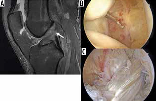
Full thickness anterior cruciate ligament (ACL) tear and recon- struction. A) Sagittal proton density-weighted fat-saturated magnetic resonance image in a 23-year-old female demonstrates complete discon- tinuity of the proximal to mid ACL (arrow). B) Arthroscopic image confirms complete ACL tear, with ACL stumps visible. C) Subsequent arthroscopic image following ligament graft reconstruction shows an intact hamstring autograft reconstruction
Figure 19.
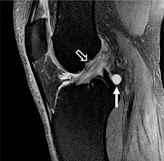
Mucoid degeneration. Sagittal proton density-weighted fat-satu- rated magnetic resonance image in a 43-year-old male with increased signal within the anterior cruciate ligament (open arrow) with intact fibres repre- sents mucoid degeneration. A cruciate ligament ganglion is incidentally noted posteriorly at the posterior cruciate ligament insertion (closed arrow)
There are several secondary signs associated with ACL tears. With a pivot shift mechanism of injury, there is often bone marrow oedema-like signal intensity consistent with osseous impaction along the terminal sulcus of the lateral femoral condyle (“deep femoral notch” sign) as well as along the posterolateral tibial plateau (Figu-re 20). With a hyperextension mechanism of injury, there are characteristic osseous contusions of the anterior tibial plateau and anterior femoral condyles. The Segond fracture, which is an osseous avulsion fracture of the anterolateral ligament from the lateral proximal tibia, is highly associated with ACL injury (Figure 20). With complete ACL tears, there is often anterior translation of the tibia with respect to the femur (> 7 mm), known as the “anterior drawer” sign. Anterior tibial subluxation resulting in uncovering of the posterior horn of the lateral meniscus, and visualisation of the entire lateral collateral ligament (LCL) on a single coronal image are also secondary signs of ACL injury. PCL buckling and shear injury to the infrapatellar fat pad are often present as well.
Figure 20.
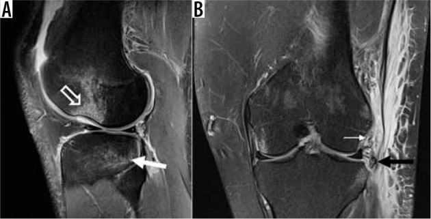
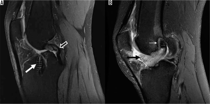
Secondary signs of anterior cruciate ligament (ACL) tear. A) Sagittal proton density-weighted (PDW) fat-saturated (FS) magnetic resonance (MR) image in a 25-year-old male shows the characteristic osseous contusion pat- tern in ACL injuries from a pivot-shift mechanism, with contusion/impaction along the terminal sulcus of the lateral femoral condyle (open arrow) and the posterior tibial plateau (closed arrow). B) Sagittal PDW FS MR image from a different patient with an ACL injury shows a Segond fracture (black arrow) and injury to the underlying anterolateral ligament (thin, white arrow)
Primary ACL repairs have a high rate of failure. As a result, when the ACL is torn, graft material, either cadaveric allograft, or patellar or hamstring (semitendinosus and gracilis) tendon autologous graft, is frequently used to reconstruct the ligament (Figures 18 and 21). Previously, single-bundle ACL graft reconstruction with repair of the anteromedial bundle was the treatment of ACL tears; more recently double-bundle reconstruction has gained popularity with some orthopaedic surgeons to restore function of both ACL bundles [44].
Figure 21.
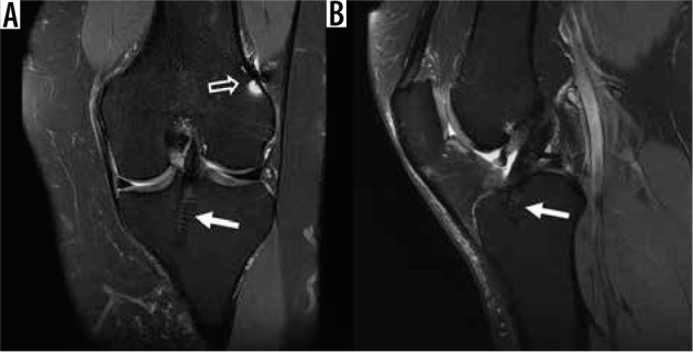
Single bundle anterior cruciate ligament (ACL) reconstruction. A) Coronal and B) sagittal proton density-weighted fat-saturated magnetic resonance images in a 41-year-old female post ACL reconstruction, with intact graft. Note the tibial interference screw (closed arrow) and the fem- oral Endobutton susceptibility artifact (open arrow) related to graft fixation
MRI is used to evaluate graft integrity and to identify potential post-surgical complications [55]. Potential reconstruction complications include graft tear, graft impingement, arthrofibrosis, ganglion cyst formation, tunnel widening/resorption, hardware failure, and osteoarthritis. The graft is anchored within tunnels in the femur and tibia with interference screws, bioabsorbable screws, or Endobuttons. Appropriate tunnel positioning is needed for proper function of the ACL graft. The inferior aspect of the femoral tunnel should be at the intersection of the posterior femoral cortex and the posterior physeal scar corresponding to the posterior intercondylar roof on sagittal MR images [55–57]. On coronal MR images, the femoral tunnel should be at the 10:00-11:00 o’clock position in the right knee and 1:00-2:00 o’clock position in the left knee, respectively [55,57]. The tibial tunnel should be parallel to the slope of the intercondylar notch but be posterior to it on sagittal MR images, and it should open on the tibial intercondylar eminence on coronal images [55]. On all three imaging planes, the graft should appear intact, with low to intermediate signal (Figure 21). If there is disruption or absence of graft fibres, a rupture of the graft is likely, and abnormal calibre reduction may reflect partial graft tearing (Figure 22).
Figure 22.
Anterior cruciate ligament (ACL) reconstruction complications. A) Sagittal proton density-weighted (PDW) fat-saturated (FS) magnetic resonance (MR) image in a 51-year-old male with completely absent ACL graft reconstruction representing tear of ACL reconstruction. There is an abnormally vertically oriented tibial tunnel interference screw present (closed arrow). Note the buckled appearance of the posterior cruciate ligament (open arrow). B) Sagittal PDW FS MR image in an 18-year-old female who is 3 years status post ACL reconstruction, with arthrofibrosis at the anterior aspect of the intercondylar notch, called a “cyclops lesion” (black arrow). A femoral interference screw is partially visible, and there is a thin halo of intermediate signal surrounding it (small arrow), which may represent granulation reaction that can form adjacent to intraosseous device constructed from bioabsorbable materials
Secondary signs of graft tear include new or progressive anterior tibial translation uncovering of the posterior horn of the lateral meniscus [44,57]. Although abnormal signal within the graft with intact fibres may suggest a partial tear, as in native ACL, intermediate signal can be seen from approximately four to eight months after reconstruction, thought to be due to graft revascularisation and synovialisation [51,57-59]. Semitendinosus and gracilis tendon grafts are composed of four separate strands, such that fluid signal can normally be present dissecting between the strands of the graft [57].
Extension lag is a potential postoperative complication, usually a result of either graft impingement or arthrofibrosis [55]. An anteriorly placed tibial tunnel can result in impingement of the graft in the intercondylar notch (Figure 23). If the tibial tunnel is too lateral, which can be identified on MRI, the graft can impinge on the inner aspect of the lateral femoral condyle [57]. Additionally, there may be increased signal intensity within the distal two-thirds of the graft, at the site of graft impingement [55]. Impingement may be treated with notchplasty. Focal arthrofibrosis, also known as a cyclops lesion, represents localised fibrosis anterior to the distal portion of the ACL graft, resulting in mechanical obstruction to knee extension [55]. On MRI, arthrofibrosis appears as a nodular, intermediate signal lesion anterior the inferior ACL graft (Figure 22). Cystic degeneration of the tibial tunnel can occur secondary to incomplete incorporation of allograft tissue, allograft tissue necrosis, or extrusion of joint fluid into the tunnel. Occasionally, the cystic-like material can extend superficial to the tibial tunnel into the overlying pretibial subcutaneous tissues. Cystic degeneration of the tibial tunnel manifests as increased signal along the tunnel on fluid-sensitive images (Figure 23). Particularly in patients receiving hamstring autografts, tibial tunnel widening can be seen. Although its significance is not fully understood, it is felt to represent graft micromotion, with related “windshield wiper” or ‘bungee cord” effects, and possibly secondary inflammation [60,61].
Figure 23.
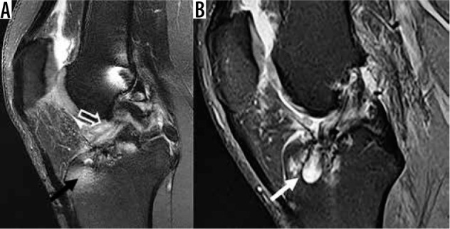
Anterior cruciate ligament (ACL) reconstruction complications. A) Sagittal proton density-weighted (PDW) fat-saturated (FS) magnetic resonance (MR) image following ACL reconstruction, with an anteriorly positioned tibial tunnel (black arrow), associated with impingement of the ACL graft along the intercondylar roof (open arrow). B) Sagittal PDW FS MR image in a different patient following ACL reconstruction shows cystic de- generative changes along the tibial tunnel (white arrow)
Posterior cruciate ligament
The PCL originates from the lateral aspect of the medial femoral condyle within the anterior intercondylar notch and inserts distally onto the posterior tibial intercondylar fossa adjacent the root of the medial meniscus. It consists of two separate bundles: the larger anterolateral bundle and smaller posteromedial bundle. The anterolateral bundle is maximally taut in flexion, and the posteromedial bundle is maximally taut in extension. The PCL serves to limit posterior translation of the tibia as well as external rotation of the tibia [44,62].
On MRI, the PCL appears as a curvilinear, homogeneous low signal band extending proximally from the femur to the tibia, and it is divided into a proximal, horizontal segment and a distal, vertical segment. The portion between the two segments reflecting angular change in orientation is called the genu. The ligament should be closely inspected on axial, sagittal, and coronal images for alterations in contour, thickness, and signal. The anteroposterior thickness of the PCL should be no greater than 6 mm [63] (Figure 24).
Figure 24.
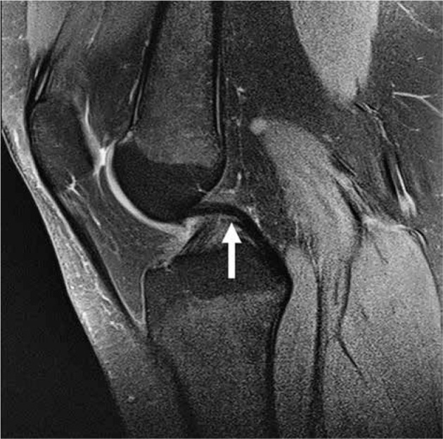
Normal posterior cruciate ligament. Sagittal proton density- weighted fat-saturated image in a 15-year-old female with normal posterior cruciate ligament (arrow). The ligament is relatively uniform in thickness and dark in signal
Injuries to the PCL are less common than to the ACL; they are often caused by motor vehicle accidents and athletic injuries [62,64,65]. Mechanisms of injury result in stretching of the ligament and include posteriorly-directed force to the anterior proximal tibia with a flexed knee, hyperextension, hyperflexion, and external tibial rotation [44,63].
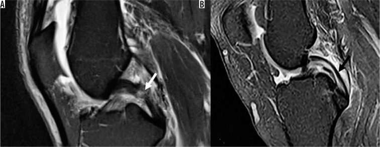
On MRI, PCL rupture presents with focal complete discontinuity of fibres. However, partial thickness PCL tears are much more common. They commonly result in thickening of the ligament, and there may be globular or striated intrasubstance signal abnormality that extends to the ligament surface that is greater on PDW images than on T2W images; however, the ligament fibres may appear intact [63] (Figure 25A). In a study of 34 patients with surgically proven PCL tears, who had had preoperative knee MRIs, Rodriguez et al. reported that thickening of the distal, vertical segment of the PCL greater than or equal to 7 mm in anteroposterior dimension on sagittal T2W images had a sensitivity and specificity in excess of 90% for both full-thickness and partial-thickness tears [44,63]. As a result, the authors proposed a distal PCL anteroposterior measurement of 6 mm or less should be considered normal, while a measurement of 7 mm or more was suggestive of a complete or partial tear. Although a measurement between 6 and 7 mm was indeterminate, the authors found the distal PCL could measure up to 8 mm in normal subjects, and the absence of intermediate intrasubstance signal strongly suggested the ligament was normal. Like the ACL, the PCL may undergo mucoid degeneration, with internal signal alteration, but this can be differentiated from a tear because the abnormal signal will appear to be intra-ligamentous in a “tram track” pattern, and not extend through the margins of the PCL in mucoid degeneration (Figure 25B) [44,66]. Chronic PCL tears demonstrate absent or diminutive appearance of the ligament, but the ligament may appear intact in more than 70% of chronic injuries [44, 67]. PCL traction injury may result in osseous avulsion of the posterior tibial plateau (Figure 26).
Figure 25.
Posterior cruciate ligament (PCL): partial tear and mucoid degeneration. A) Sagittal proton density-weighted (PDW) fat-saturated (FS) magnetic resonance (MR) image in an 84-year-old male with increased signal in midportion of PCL representing prior partial PCL tear (arrow). B) Sagittal PDW FS magnetic resonance image in a different patient shows “tram track” appearance (arrow) of PCL consistent with mucoid degeneration
Figure 26.
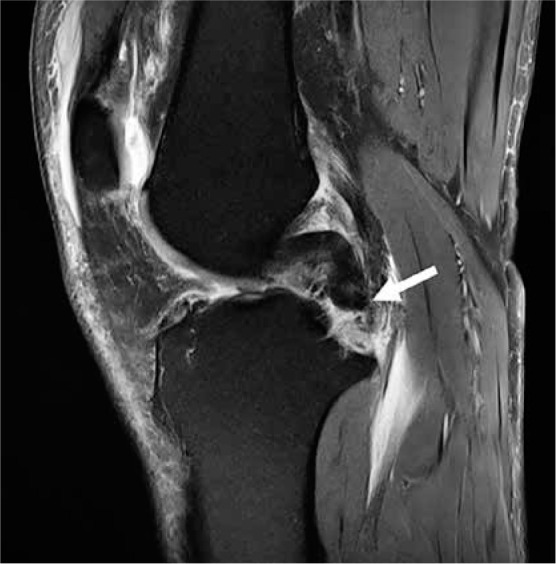
Posterior cruciate ligament (PCL): osseous avulsion. Sagittal proton density-weighted fat-saturated magnetic resonance image in a 54-year-old male shows a complete avulsion of the PCL from its tibial insertion (arrow)
When a PCL injury occurs following a posteriorly directed force on the anterior proximal tibia with the knee flexed, such as in the setting of a dashboard injury in a motor vehicle accident, there are often characteristic osseous contusions of the proximal anterior tibia and the posterior distal femur (Figure 27). With hyperextension mechanism of injury, there are characteristic osseous contusions of the anterior tibial plateau and anterior femoral condyles. PCL injury may also be associated with a reverse Segond fracture, which is an avulsion injury of the deep meniscotibial component of the medial collateral ligament (MCL) from the medial tibial plateau secondary to internal rotation and valgus stress (Figure 27).
Figure 27.
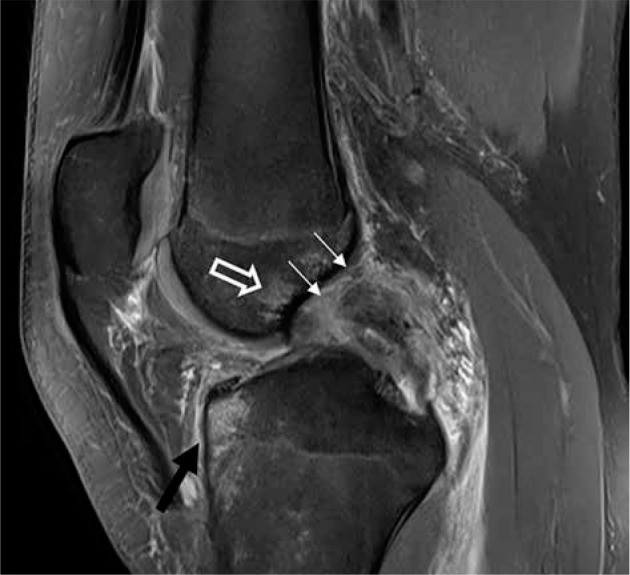
Posterior cruciate ligament (PCL): complete tear and secondary signs of injury. Sagittal proton density-weighted fat-saturated magnetic resonance image in a 44-year-old male with characteristic osseous contusions in the an- terior proximal tibia (black arrow) and distal femur (open arrow), which occur with PCL injuries. The PCL is thickened, with increased signal and indistinct fibres, and a complete proximal tear from its femoral origin (thin, white arrows)
Frequently, PCL injuries are treated conservatively, unless the patient shows clear instability and ongoing pain. In these cases, some institutions will perform surgical reconstruction of the ligament [68].
Medial knee: medial collateral ligament and posteromedial corner
Medial collateral ligament
The MCL serves as the major posteromedial stabiliser of the knee, and it consists of superficial and deep layers. The superficial MCL originates posterior and proximal to the medial femoral epicondyle and inserts onto the semimembranosus tendon and the posteromedial crest of the tibia [44,69]. The deep MCL is thickening of the medial joint capsule, with meniscofemoral and meniscotibial components [44,69]. The superficial MCL is the primary stabiliser to valgus force as well as to rotation of the tibia; the deep MCL provides secondary restraint to valgus force and acts as a restraint to internal rotation of the tibia [44].
The MCL should be evaluated on axial and coronal images, and its superficial band should appear as a contiguous, relatively uniformly thick, low signal intensity band extending from the femoral epicondyle to its tibial insertion, without surrounding oedema or intrasubstance signal alteration. The components of the deep MCL are normally thinner and attach the periphery of the medial meniscus to the medial femoral condyle and medial tibial plateau close to the joint line. As a result, they may be difficult to visualise on routine MRI unless the ligament has been injured.
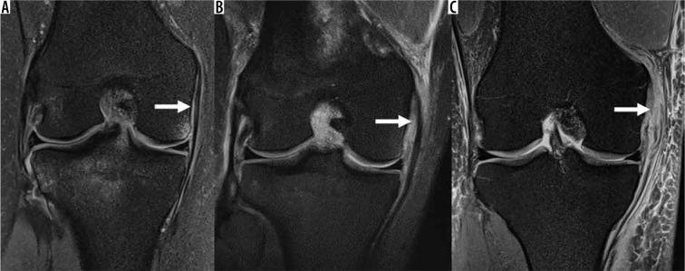
MCL injuries are common, usually in the setting of valgus injury [44,70,71]. A grading system is utilised for MCL injuries. Grade 1 injuries show an intact MCL with surrounding soft tissue oedema. With Grade 2 MCL injuries, the ligament is partially torn. With Grade 3 injuries, the MCL is disrupted; the tear is full thickness but does not need to extend the full width of the MCL. On MRI, grade 2 and 3 tears can be seen with partial or complete alteration of the fibres, with increased signal within the normally low signal MCL (Figure 28). The MCL Stener lesion is associated with ACL tears; this injury occurs when the superficial tibial fibres of the MCL are torn and are displaced over the pes anserine tendons, preventing healing of the MCL. It is important to note that soft tissue oedema surrounding the MCL may be secondary to non-traumatic causes such as ruptured popliteal cyst, underlying medial meniscal pathology with meniscal extrusion, medial compartment osteoarthritis, MCL bursitis, or to injury of the medial patellar retinaculum or medial patellofemoral ligament (MPFL) rather than injury of the MCL [72].
Figure 28.
Medial collateral ligament (MCL) injuries. Coronal proton density-weighted fat-saturated magnetic resonance images in a: A) 20-year-old female with oedema surrounding the MCL without disruption of the ligament fibres (arrow), consistent with a low-grade injury/grade I MCL sprain, B) 21-year-old female with oedema and thickening of the MCL fibres (arrow), consistent with partial-thickness tear/grade II MCL sprain, C) 45-year-old male with oedema and discontinuity of the proximal MCL fibres (arrow), consistent with a full-thickness tear/grade III MCL sprain
Posteromedial corner
The posteromedial corner (PMC) also provides posteromedial stabilisation of the knee. The PMC consists of structures between the posterior MCL and the medial border of the PCL, and includes the semimembranosus tendon, the oblique popliteal ligament, the posterior oblique ligament, the posteromedial joint capsule, and the posterior horn of the medial meniscus [73]. On MRI, the semimembranosus tendon is easily seen, although the other components of the PMC may be difficult to see when they are normal because they are thin and closely apposed to the bones and periphery of the medial meniscus. Injury of the semimembranosus tendon may be seen with tendon thickening, peritendinous oedema, complete or partial tendon tearing, and posteromedial proximal tibial metaphyseal subentheseal bone marrow oedema that reflects avulsive stress. Injuries to the remaining structures can be diagnosed when there is posteromedial soft tissue oedema along the joint capsule that is not related to rupture of a popliteal cyst or leakage of fluid from an adjacent bursa, such as the pes anserine bursa. Injuries to the PMC often occur with ACL or PCL tears and can lead to anteromedial rotational instability. Unrecognised PMC injuries can lead to premature failure of an ACL or PCL graft repair [73,74].
Lateral knee: iliotibial band and posterolateral corner
Iliotibial band
The iliotibial band (ITB) is a distal continuation of the deep fascia lata of the thigh which inserts onto Gerdy’s tubercle on the anterolateral proximal tibia. The ITB provides lateral stability at the knee, with restraint to varus stress [75].
On MRI, the ITB is seen as a broad, thick band of low signal extending from the anterolateral thigh to attach to Gerdy’s tubercle on the tibia. ITB friction syndrome is often seen in running athletes, with oedema signal tracking both superficial and deep to the ITB on fluid-sensitive MRI pulse sequences (Figure 29). Traumatic injury isolated to the ITB is uncommon; injuries usually occur as part of a multi-ligamentous injury to the knee [75]. Tear of the ITB can be identified on MRI as disrupted fibres, with fluid-filled clefts, and potential retraction of the torn fibres.
Figure 29.
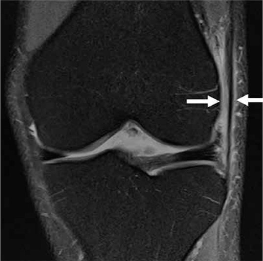
Iliotibial band syndrome. Coronal proton density-weighted fat-saturated magnetic resonance image of a 34-year-old male with ilio- tibial band friction syndrome, with fluid and oedema adjacent to the lateral femoral condyle and surrounding the iliotibial band (arrows)
Posterolateral corner
The posterolateral corner (PLC) of the knee provides posterolateral stability to the knee and is composed of the fibular collateral ligament, biceps femoris tendon, popliteus muscle and tendon, popliteofibular ligament, arcuate ligament, and, when present, the fabella and fabellofibular ligament.
The fibular collateral ligament, also known as the true LCL or LCL proper, provides primary restraint to varus stress; it originates posterior to the lateral femoral epicondyle and inserts on the lateral aspect of the fibular head, often forming a conjoint tendon with the distal biceps femoris [44,76,77]. The popliteus muscle originates from the posteromedial proximal tibia to insert proximally along the lateral femoral condyle as well as along the posterior horn of the lateral meniscus [44,76,77]. The popliteus tendon attaches to the fibula as the popliteofibular ligament. The arcuate ligament is a focal thickening of the posterolateral joint capsule in the region of the popliteal hiatus, and it is poorly visualised on MRI [44,77,78]. The fabellofibular ligament originates at the fabella and inserts on the fibular styloid process [44,76-78].
The fibular collateral ligament, popliteus tendon, and biceps femoris tendon are well visualised on MRI. The popliteofibular ligament is present in nearly everyone, while the arcuate ligament and fabellofibular ligament are variably present. The fibular collateral ligament, popliteus tendon, biceps femoris tendon, popliteofibular ligament, arcuate ligament, and fabellofibular ligament are linear, low signal structures that appear contiguous between their origins and insertions.
Injuries to the PLC typically occur in the setting of trauma and are often associated with cruciate ligament (particularly PCL) injuries or multi-ligamentous injuries in the setting of knee dislocation [76,78]. An arcuate fracture is an avulsion fracture from the fibular head styloid process at the insertion of the fabellofibular, popliteofibular, and arcuate ligaments; this avulsion is associated with PLC and PCL injuries (Figure 30). If there is MRI evidence of injury to the popliteus tendon and the fibular collateral ligament, the popliteofibular ligament should be closely scrutinised for potential injury [78]. Failure to repair the PLC can result in failure of cruciate ligament reconstruction as well as the development of osteoarthritis [76,78]. The PLC structures can be repaired or reconstructed by several different surgical techniques.
Figure 30.
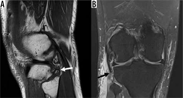
Posterolateral corner (PLC) injury. A) Sagittal T1W non-fat-satu- rated and (B) coronal proton density-weighted fat-saturated magnetic res- onance images in a 24-year-old male with a PLC injury. An “arcuate” fracture is present with osseous avulsion of the fibular head styloid process (white arrow), and there is a complete avulsion of the lateral collateral ligament from its fibular attachment with proximal retraction close to the joint line (black arrow)
On MRI, focal oedema along the posterolateral joint capsule on fluid-sensitive sequences may indicate a low-grade PLC injury. Partial tearing is identified by thickening and increased signal intensity involving the PLC structures, and a full-thickness tear is identified by discrete fibre discontinuity and often a fluid gap [76]. Injury can also be identified with ligamentous avulsions, peri-ligamentous oedema, and myotendinous injuries (Figure 30).
Knee dislocations
Knee dislocations are relatively rare but often result in multiligamentous injuries, involving the cruciate ligaments and either the MCL or the PLC. Posterior knee dislocations almost always result in injury to the popliteal artery. The peroneal and tibial nerves can also be injured. Periarticular fractures are also common.
Extensor mechanism: quadriceps tendon, patellar tendon, medial/lateral patellar retinacula
The extensor mechanism of the knee allows for dynamic knee extension and patellofemoral stabilisation [69]. It primarily consists of the quadriceps tendon, patella, patellar tendon, tibial tuberosity, medial and lateral patellar retinacula, and the vastus musculature [79].
Quadriceps tendon
The quadriceps tendon is formed by contributions from the rectus femoris (superficial layer), vastus lateralis and vastus medialis (middle layer), and vastus intermedius (deep layer) muscles. The normal quadriceps tendon appears laminated on MRI secondary to this layered configuration and interdigitating fat [68]. Superficial fibres of the rectus femoris extend along the anterior patella to the patellar tendon as the prepatellar quadriceps continuation [80-82].
Quadriceps tendinosis is typically related to overuse. On MRI, the tendon becomes enlarged, with increased signal. Quadriceps tendon tears may be due to an acute injury or secondary to chronic tendinosis. Tears may also be secondary to systemic disease or medication use. Tears usually occur 1–2 cm proximal to the patella and at the patellar insertion, where the tendon is relatively avascular [79-81]. Partial tears most commonly affect the anterior rectus femoris portion [79-81] and appear as a partial thickness, fluid-filled gap on MRI, without complete disruption of the tendon. Complete quadriceps tendon tears appear on MRI as complete disruption of the tendon fibres, a full thickness, fluid-filled gap, a retracted tendon stump, an inferiorly positioned patella (patella baja), and a wavy patellar tendon (Figure 31). Acute, complete tears are treated with surgical repair, while treatment of partial tears is generally conservative.
Figure 31.
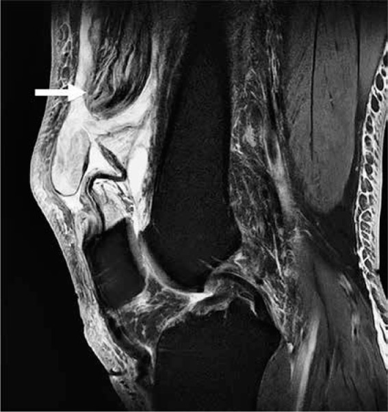
Quadriceps tendon tear. Sagittal proton density-weighted fat- saturated magnetic resonance image in a 59-year-old male with a quadri- ceps tendon tear, with complete discontinuity and retraction of quadriceps tendon stump (arrow), and associated patella baja
Patellar tendon
The patellar tendon, technically a ligament, is a band that continues distally from the quadriceps continuation along the anterior patellar surface, extends from the inferior patella, and fans out along its insertion along the tibial tuberosity.
The normal patellar tendon demonstrates low signal intensity on MRI. Often, there is triangular intermediate signal involving the posterior half of its patellar attachment, and occasionally there may be intermediate signal its tibial insertion. This is probably secondary to a combination of magic angle phenomenon and histological changes within the tendon provided there are no other signs of tendinopathy [79,83]. When the knee is in full extension and the quadriceps muscles are relaxed, the tendon can buckle and be associated with multiple transversely oriented bands of intermediate signal intensity at the sites of buckling that are also related to magic angle phenomenon [84].
Patellar tendinosis is most commonly due to overuse, such as from running and jumping activities. On MRI, the tendon will appear thickened with increased signal. The proximal tendon is most often affected, and there may be associated reactive bone marrow oedema in the inferior patella along with surrounding prepatellar or Hoffa’s fat pad oedema.
As with the quadriceps tendon, the patellar tendon may tear due to an acute injury or in the setting of tendinosis (Figure 32). Tears may be partial or complete. Partial tears appear as partial thickness, fluid-filled defects on MRI, without complete disruption of the tendon. Interstitial tears are partial thickness tears that occur within the tendon and do not extend to the tendon surface. Complete patellar tendon tears appear on MRI as complete disruption of the tendon fibres, a full-thickness fluid-filled gap, a retracted tendon stump, a superiorly positioned patella (patella alta), and a wavy quadriceps tendon. Like quadriceps tendon tears, acute, complete patellar tendon tears are treated with surgical repair, whereas treatment of partial tears is conservative.
Figure 32.
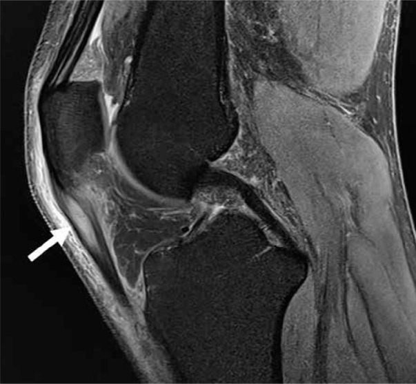
Patellar tendinosis. Sagittal proton density-weighted fat-satu- rated magnetic resonance image in a 49-year-old male with severe patellar tendinosis with interstitial tearing (arrow)
Medial and lateral patellar retinacula
The patellar retinacula provide stability to the patella. The retinacula are linear, low-signal, fibrous bands extending medial and laterally from the patella to the femoral condyles. The medial retinaculum is multilayered, with the most cranial and vital component being MPFL [85]. The MPFL attaches on the femur between the medial femoral epicondyle and the adductor tubercle, and along the superomedial patella, and it provides restraint to lateral patellar dislocation.
Patellar dislocation is most common in young females. It is often transient, and occurs most frequently laterally, with injury to the MPFL as the medial patellar facet impacts on the lateral femoral condyle during reduction [80]. With MRI, there is often disruption of the MPFL and/or patellar retinaculum, osseous contusions of the inferomedial patellar facet and anterolateral lateral femoral condyle, and associated cartilaginous injuries. Occasionally, there may be an osseous MPFL avulsion from its medial patellar attachment, which may not be diagnosed at the time of initial injury and be associated with persistent instability. The MPFL may be injured at any location, but is most commonly injured at its femoral attachment [79,80]. MRI findings of MPFL injury include thickening, intra-ligamentous fluid, wavy fibres, and fibre discontinuity [86]; often, fluid extends along the vastus medialis oblique (VMO) muscle, which comprise the inferior vastus medialis muscle fibres that attach directly onto the MPFL. As a result, VMO injury is also associated with MPFL injury and patellofemoral instability and should be reported if seen on MRI (Figure 33).
Figure 33.
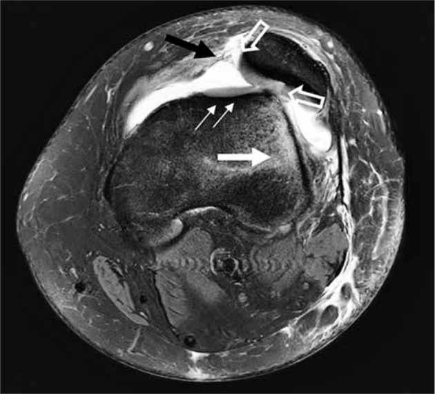
Lateral patellar dislocation. Axial proton density-weighted fat-saturated magnetic resonance image in a 13-year-old female with prior lateral patellar dislocation, currently with lateral subluxation. Note the dysplastic trochlear groove (thin, white arrows) and bone contusion in the lateral femoral condyle (thicker, white arrow). Cartilage injuries (open arrows) are present along the patella. The medial patellofemoral ligament is avulsed from its patellar attachment (black arrow)
Patellofemoral instability
Patellofemoral instability is a clinical syndrome secondary to anatomic abnormalities in the patellofemoral joint, in which the patella is prone to recurrent lateral subluxation or dislocation. The three major anatomic abnormalities that predispose to patellar instability are trochlear dysplasia (Figure 33), patella alta, and lateralisation of the tibial tuberosity. Trochlear dysplasia, or flattening, can be quantified by lateral trochlear inclination, facet asymmetry, trochlear depth, and trochlear groove angle (normal less than 144 degrees). Patellar height is most commonly evaluated using the Insall-Salvati index, with a ratio greater than 1.3 considered patella alta on MRI. Lateralisation of the tibial tuberosity is a risk factor for instability because it permits the patella to be pulled laterally in flexion, and it is evaluated by measuring the distance from the tibial tubercle to the trochlear groove (TT-TG). TT-TG values measuring less than 15 mm are normal, borderline values measure between 15-20 mm, and abnormal values measure greater than 20 mm. An abnormally high TT-TG does not predict whether a patient will suffer from lateral patellar maltracking but it is used to guide surgical management [87].
Peripatellar fat pad oedema can be seen in the setting of various impingements and can be a cause of anterior knee pain. Oedema of the superolateral aspect of the infrapatellar fat pad suggests impingement between the lateral femoral condyle and the proximal patellar tendon, which is known as patellar tendon-lateral femoral condyle friction syndrome and is commonly associated with lateral patellar maltracking. Oedema in the suprapatellar and prefemoral fat pads may also be seen in the setting of fat pad impingement.
In the later stages of lateral patellofemoral instability, the chronically increased lateral patellofemoral forces result in lateral patellofemoral-predominant articular cartilage loss and subsequent osteoarthritis. As a result, patients with lateral patellofemoral-predominant chondral loss commonly suffer from lateral patellar maltracking.
Articular cartilage
Cartilage evaluation
Osteoarthritis affects the knee more commonly than any other joint, and imaging is commonly used to detect cartilage loss before it can progress to osteoarthritis. Furthermore, the knee, especially the patella, contains thicker cartilage than other joints, which makes MRI particularly effective in assessing the cartilage of this joint.
The most widely used MRI cartilage grading system is the International Cartilage Repair Society arthroscopic grading system, in which grade 0 is normal healthy cartilage; grade 1 is a soft spot, blister, or superficial wear of the cartilage; grade 2 is minor tears of less than one-half the thickness of the cartilage layer; grade 3 is deep crevices of more than half the thickness of the cartilage layer; and grade 4 is full thickness cartilage tearing that exposes the underlying (subchondral) bone.
The modified Outerbridge classification system published in 2006 is an alternative chondral injury grading system routinely used clinically, which has been adapted to MRI and consists of four grades. Grade I injury is cartilage that is normal in contour with alterations in signal intensity on MRI, which is shown by softening of the cartilage at arthroscopy. On MRI, grade II injury is fissuring or blister-like swelling of the articular cartilage, extending to the surface. At arthroscopy, grade II injury demonstrates fissuring and fragmentation within soft areas of articular cartilage. Grade III injury is partial thickness cartilage loss with focal ulcerations on MRI, correlating with partial thickness cartilage loss with fibrillation (crab-meat appearance) at arthroscopy. Grade IV injury is full-thickness cartilage loss with underlying bone marrow oedema-like signal intensity changes on MRI, which is visible as cartilage destruction/ulceration with exposed subchondral bone at arthroscopy (Figure 34).
Figure 34.
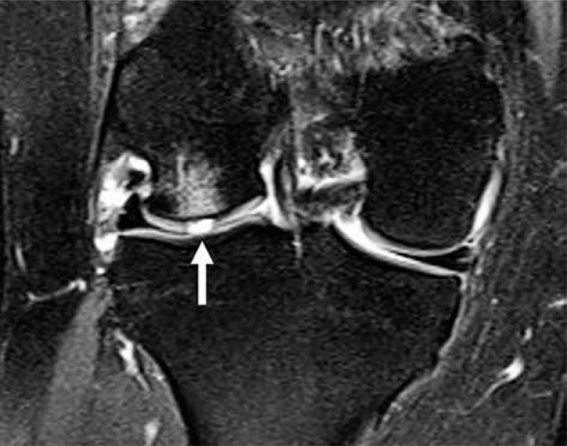
Cartilage defect. Coronal proton density-weighted fat-saturat- ed magnetic resonance image in a 36-year-old male with a full thickness (grade 4) lateral femoral condyle cartilaginous defect (arrow) and adjacent subchondral bone marrow oedema-like signal
Osteochondritis dissecans
Osteochondritis dissecans of the femoral condyles is a common articular surface lesion in adolescents and adults. The majority of these lesions are post traumatic [88] and are located on the medial femoral condyle, classically along its lateral aspect [89]. MRI is used to assess the articular cartilage fragment for signs of fragment instability, which is helpful in assessing prognosis and determining treatment options. Osteochondral injury results in a curvilinear fracture line extending through the articular cartilage and underlying subarticular bone plate, which is visible on MRI contacting the bone-cartilage junction at both ends, often with surrounding subchondral bone marrow oedema-like signal intensity. The fracture line may not always be identified extending through the articular cartilage on MRI. Osteochondral lesions can be displaced or nondisplaced, and the nondisplaced injuries are generally divided into stable and unstable lesions (Figure 35). The presence of a fluid/high signal line on fluid-sensitive imaging around the bone fragment usually indicates an unstable lesion. MRA can be helpful to confirm an unstable osteochondral fragment if there is dilute gadolinium contrast interposed between the osteochondral fragment and the donor site. Focal cyst-like areas beneath the bone fragment may also suggest fragment instability [88].
Figure 35.
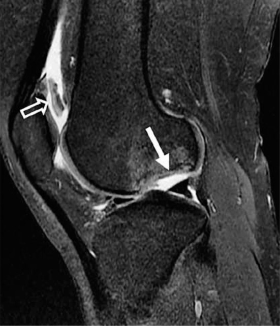
Osteochondritis dissecans. Sagittal proton density-weighted fat-saturated magnetic resonance image in a 23-year-old female with a large osteochondral defect of the lateral femoral condyle (closed arrow) with adjacent marrow oedema-like signal abnormality. The osteochondral fragment is displaced into the suprapatellar recess (open arrow)
For displaced and unstable lesions, numerous surgical approaches are available, including drilling, microfracture, abrasion, bone grafting, replacement of the bone fragment and pinning, open biological resurfacing procedures (autologous chondrocyte implantation, perichondral autografts, mosaicplasty, and shell allografts), and fragment/intra-articular body removal. Treatment for stable lesions is rest and immobilisation, which is frequently successful in younger patients prior to growth plate closure [90].
Cartilage repair techniques and magnetic resonance imaging features of repair tissue
Articular cartilage injuries are common and can be surgically treated to improve symptoms and to prevent or delay the onset of osteoarthritis. The surgical treatment options consist of marrow stimulation techniques (microfracture), osteochondral grafting (autografting/allografting), and autologous chondrocyte implantation. Standard MRI of repair tissue offers noninvasive initial assessment of implantation success and subsequent monitoring of cartilage healing. The repaired sites should be evaluated for the degree of defect filling with repair tissue, integration of repair tissue with adjacent tissue, and appearance of underlying bone [90-93]. The most frequently used grading system for postoperative scoring of repaired cartilage is MR observation of cartilage repair tissue (MOCART), which has primarily been used in research studies and is not well established in clinical diagnostic radiology [94].
Microfracture
Microfracture is optimally used in patients with a less than 4 cm2 focal femoral condyle chondral defect [82]. Arthroscopically, a small awl is used to generate 1-2 mm microfracture holes from the defect surface to the subchondral bone to produce bleeding [95]. The blood clot that fills the cartilage defect contains multi-potential stem cells from the marrow, which ultimately leads to fibrocartilage formation to heal the defect [91].
On MRI, microfracture repair tissue may initially appear thin or indistinct, and it appears hyperintense to native cartilage on T2W images [94]. It decreases in signal intensity as it matures over 1-2 years before filling the defect with a smooth and well-defined surface [94]. Treatment failure and poor outcomes are associated with persistent defects, incomplete integration, or persistent bone marrow oedema-like signal intensity after two years [94].
Osteochondral auto- and allografting (mosaicplasty)
For femoral lesions with area 1-4 cm2 [91], osteochondral autografts can be taken from the patient’s own non-weight-bearing cartilage [93] (lateral femoral condyle or trochlea). This technique has the advantage of lower rates of graft rejection and higher rates of graft incorporation. For larger lesions with bone and cartilage loss, osteochondral allografts can be harvested from a donor [94].
On MRI, the osteochondral grafts should initially completely fill the defect with uniform signal intensity cartilage [94]. As the graft incorporates, the articular surface of the graft and adjacent native cartilage should be smooth and congruent, even though the subchondral bone plate is often incongruent with the adjacent bone owing to differences in cartilage thickness of the donor and transplant sites (Figure 36) [94]. Postoperatively, bone marrow oedema-like signal intensity is commonly seen within the graft and adjacent bone and resolves over time as the bone incorporates, but it may persist for several years [96]. Persistent bone marrow oedema-like signal intensity after 18 months and subchondral cyst-like formation are concerning for poor tissue integration [94].
Figure 36.
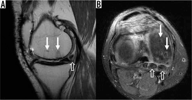
Mosaicplasty. A) Sagittal proton density-weighted (PDW) non- fat-saturated and (B) axial PDW fat-saturated images in a 41-year-old male with cylindrically shaped osteochondral grafts/bone plugs (closed arrows in A and B). Also note the intra-articular bodies present (open arrows in A and B)
Autologous chondrocyte implantation
Autologous chondrocyte implantation is a two-stage operation. In the first stage, chondrocytes are harvested at arthrotomy, usually from the tibial spines [93], and then cultured in vitro for 3-5 weeks [91]. The second stage arthrotomy then implants the cultured chondrocytes under a periosteal or synthetic collagen flap, which leads to the formation of hyaline-like repair tissue [93].
On MRI, over the course of 1-2 years, autologous chondrocyte implantation repair tissue transforms from hyperintense to that of native cartilage. Incomplete peripheral integration and subchondral bone marrow oedema-like signal intensity should progressively incorporate and resolve, respectively [94]. Persistence of these findings may indicate treatment failure.
The repaired sites should be evaluated for the degree of defect filling on both the sagittal and coronal planes; the extent of repair tissue integration; the signal intensity of the repaired area compared to the native cartilage; interface of the graft substance with the adjacent native cartilage (flush, depressed, proud); presence or absence of delamination and fissures; and the appearance/integrity of underlying bone [91,92].
Bone marrow
Normal marrow appearance
Normal bone marrow consists of red (40% fat) and yellow (80% fat) marrow; the distribution of red and yellow marrow varies over time, depending on age and homeostatic requirements. On MRI, normal adult red or yellow marrow is hyperintense on T1W imaging as compared to the adjacent musculature, and red marrow has signal intensity less than fat on T2W NFS imaging.
Fractures
On MRI, fractures are characterised by low signal linear intensity on T1W images, surrounded by poorly defined areas of high signal bone marrow oedema-like signal intensity on fluid-sensitive sequences. Bone contusions show similar ill-defined areas of high signal, bone marrow oedema-like signal intensity on fluid-sensitive sequences in the absence of a fracture line. MRI is particularly useful in the setting of radiographically occult fracture detection.
Subchondral insufficiency fractures
Previously diagnosed as spontaneous osteonecrosis of the knee, this entity is now recognised as a subchondral insufficiency fracture, which may occur with or without associated secondary necrosis. Subchondral insufficiency fractures typically occur in osteoporotic or elderly patients (average age of 70 years), whose bone is mechanically weakened [97]. On MRI, there is a linear low signal intensity fracture line beneath the distal femoral or proximal tibial weight-bearing articular surfaces on T1W images (classically the medial femoral condyle) with adjacent, pronounced bone marrow oedema-like signal intensity on T2W FS images (Figure 37) [98]. Occasionally, the fracture line may be so small and close to the subarticular bone plate that it might not be visible, and small subchondral insufficiency fractures may appear only as small areas of sclerosis. The overlying cartilage is often intact, unless there is pre-existing chondral degeneration. MRI diagnosis of these lesions is important because treatment is conservative with weight-bearing limitations.
Figure 37.
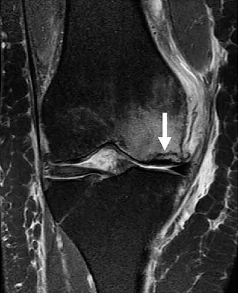
Subchondral insufficiency fracture. Coronal proton density- weight ed fat-saturated magnetic resonance image in a 68-year-old female with linear low signal intensity (arrow) beneath the weight-bearing articular surface of the medial femoral condyle, consistent with fracture with adjacent subchondral bone marrow oedema-like signal. The overlying cartilage is intact with the exception of moderate grade pre-existing chondral degeneration
Joint effusion, synovium, bursae, and cysts
Joint effusion
Several joint recesses are present within the knee, including the suprapatellar, infrapatellar, medial, lateral, and intercondylar recesses. A joint effusion, or excess of fluid within these recesses, may be caused by trauma, infection, and a variety of rheumatological conditions. On MRI, simple joint fluid is homogeneously hyperintense on T2W images and hypointense on T1W images, with only a thin rim of enhancement on post-contrast T1W FS imaging. Lipohemarthrosis and hemarthrosis will demonstrate layering of components of different signal intensities. Contrast-enhanced imaging allows better differentiation between joint effusion and synovial disorders. Thick synovial enhancement is consistent with synovitis, which can be quantified but currently is used mainly for research.
Synovial diseases
The synovium is a thin, highly vascularised membrane that lines diarthrodial synovial joints, some bursae, and tendon sheaths. Synovial diseases may be inflammatory, infectious, degenerative, traumatic, haemorrhagic, or neoplastic. Tumour-like conditions, such as pigmented villonodular synovitis, nodular synovitis, giant cell tumour of tendon sheath, synovial chondromatosis/osteochondromatosis, and lipoma arborescens, can also involve the synovium [99]. On MRI, synovial disease manifests as thickened synovium, which is commonly hyperintense on T2W FS imaging, and avidly enhances on post-contrast T1W FS imaging. Chronic synovitis may show intermediate signal intensity on the fluid-sensitive sequences.
Synovial plicae
Synovial plicae are normal anatomic structures that represent embryologic remnants of synovial membranes. Four plicae of the knee have been described: suprapatellar, infrapatellar, medial patellar, and lateral patellar. They are thin, vascularised structures with no known function. However, with chronic inflammation, they can become symptomatic (plica syndrome). On MRI, normal plicae appear as linear low signal intensity structures connected to the synovial lining, often surrounded by joint fluid (Figure 38). In medial patellar plica syndrome, the medial plica usually appears thickened on MRI and associated with medial patellofemoral synovitis and/or articular cartilage wear (fissures, defects).
Figure 38.
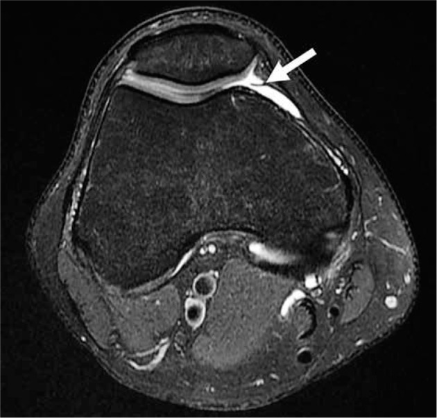
Plica. Axial proton density-weighted fat-saturated magnetic resonance image in a 30-year-old male with linear low-signal intensity non-thickened tissue connected to the synovial lining and surrounded by joint fluid, compatible with a medial patellar plica (arrow)
Cysts and bursae
Cystic lesions around the knee are frequently seen on routine imaging [100]. There are two types of cysts – ganglion cysts and synovial cysts (bursae) – which both have variable communication with the adjacent joint. Ganglion cysts are lined by fibrous connective tissue, and synovial cysts are lined by synovium.
In the posterior knee, popliteal cysts, also known as Baker’s cysts, arise between the medial head of the gastrocnemius muscle and the semimembranosus tendon, and usually communicate with the knee joint (Figure 39). Popliteal cysts are well-defined fluid collections on MRI, which is useful for the detection of internal haemorrhage, extruded intra-articular bodies or debris, or cyst rupture. The popliteus bursa is also found posteriorly at the distal aspect of the popliteus muscle tendon recess and can communicate with the tibiofibular joint.
Figure 39.
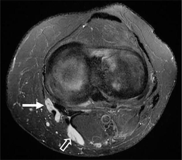
Pes anserine bursa and popliteal cyst. Axial proton density-weight- ed fat-saturated magnetic resonance image in a 62-year-old female with fluid in both the pes anserine bursa (closed arrow), located between the distal tendons of the sartorius, gracilis, and semitendinosus muscles, as well as within a popliteal (Baker’s) cyst, with fluid between the medial head of the gastrocnemius muscle and the semimembranosus tendon (open arrow)
Intraneural ganglion cysts can arise from the proximal tibiofibular joint space and extend along the articular branch of the peroneal nerve, leading to compression-related neurological symptoms; thus, early diagnosis and surgical treatment are important to prevent irreversible loss of nerve function [101]. On MRI, intraneural ganglion cysts are hypointense on T1W images, hyperintense on T2W images, and do not enhance or may show thin, smooth peripheral enhancement following intravenous gadolinium-based contrast administration (Figure 40).
Figure 40.
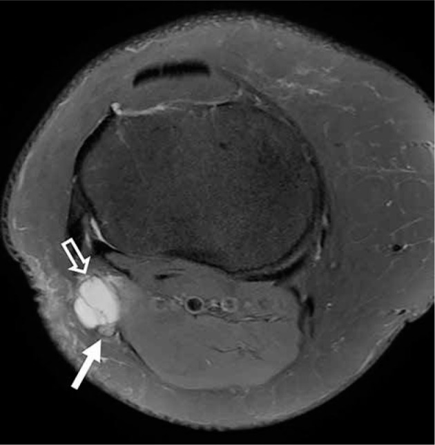
Intraneural ganglion cyst. Axial proton density-weighted fat-sat- urated magnetic resonance image in a 46-year-old female with an intran- eural ganglion cyst (open arrow) along the course of the peroneal nerve (closed arrow), just caudal to the proximal tibiofibular joint
Numerous bursae are located around the knee, commonly around tendon attachments. In the anterior knee, the suprapatellar bursa is located proximal to the knee joint capsule between the rectus femoris tendon and femur, and usually communicates with the knee joint. The pre-patellar bursa is located anterior to the patella and can extend medially or laterally. The superficial infrapatellar bursa is found anterior to the tibial tubercle, and the deep infrapatellar bursa is located between the distal patellar tendon and anterior tibia. A small amount of fluid in the deep infrapatellar bursa (< 3 mm) is a normal finding.
Along the medial knee, the pes anserine bursa lies between the conjoined distal tendons of the sartorius, gracilis, and semitendinosus muscles and the tibial attachment of the MCL (Figure 39). The semimembranosus-tibial collateral ligament bursa lies posterior and superior to the pes anserine bursa with its superficial portion situated between the semimembranosus tendon and medial collateral ligament, and its deep portion is located between the semimembranosus tendon and the medial tibial condyle. The MCL bursa is found between the deep and superficial fibres of the MCL in the central third of the knee.
Conclusions
MRI plays a significant role in diagnosis of internal derangements of the knee, detection of the bone marrow oedema-like signal pattern, and radiographically occult factures. MRI enables superb evaluation of the bones, ligaments, menisci, articular cartilage, tendons, synovium, and periarticular soft tissues of the knee joint, and guides orthopaedic treatment planning.
Conflict of interest
The authors report no conflict of interest.
References
- 1.Qi ZH, Li CF, Li ZF, et al. . Preliminary study of 3T 1H MR spectroscopy in bone and soft tissue tumors. Chin Med J 2009; 122: 39-43. [PubMed] [Google Scholar]
- 2.Chhabra A, Lee PP, Bizzell C, et al. . 3 Tesla MR neurography–technique, interpretation, and pitfalls. Skeletal Radiol 2011; 40: 1249-1260. [DOI] [PubMed] [Google Scholar]
- 3.Koff MF, Burge AJ, Koch KM, et al. . Imaging near orthopedic hardware. J Magn Reson Imaging 2017; 46: 24-39. [DOI] [PMC free article] [PubMed] [Google Scholar]
- 4.Miller JD, Nazarian S, Halperin HR. Implantable Electronic Cardiac Devices and Compatibility With Magnetic Resonance Imaging. J Am Coll Cardiol 2016; 68: 1590-1598. [DOI] [PubMed] [Google Scholar]
- 5.American College of Radiology. ACR–SPR–SSR practice parameter for the performance and interpretation of magnetic resonance imaging (MRI) of the knee. Available from: https://www.acr.org/-/media/ACR/Files/Practice-Parameters/MR-Knee.pdf. [DOI] [PubMed]
- 6.Link TM, Neumann J, Li X. Prestructural cartilage assessment using MRI. J Magn Reson Imaging 2017; 45: 949-965. [DOI] [PubMed] [Google Scholar]
- 7.Ugas MA, Huynh BH, Fox MG, et al. . MR arthrography: impact of steroids, local anesthetics, and iodinated contrast material on gadolinium signal intensity in phantoms at 1.5 and 3.0 T. Radiology 2014; 272: 475-483. [DOI] [PubMed] [Google Scholar]
- 8.Chung C, Isaza I, Angulo M, et al. . MR arthrography of the knee: how, why, when. Radiol Clin N Am 2005; 43: 733-746. [DOI] [PubMed] [Google Scholar]
- 9.Rastogi A, Davis K, Ross A, et al. . Fundamentals of joint injection. AJR Am J Roentgenol 2016; 207: 484-494. [DOI] [PubMed] [Google Scholar]
- 10.Chu CR, Izzo NJ, Coyle CH, et al. . The in vitro effects of bupivacaine on articular chondrocytes. J Bone Joint Surg Br 2008; 90: 814–820. [DOI] [PMC free article] [PubMed] [Google Scholar]
- 11.Fox AJ, Bedi A, Rodeo SA. The basic science of human knee menisci: structure, composition, and function. Sports Health 2012; 4: 340-351. [DOI] [PMC free article] [PubMed] [Google Scholar]
- 12.Nguyen J, de Smet AA, Graf B, et al. . MR Imaging based diagnosis and classification of meniscal tears. Radiographics 2014; 34: 981-999. [DOI] [PubMed] [Google Scholar]
- 13.Englund M, Guermazi A, Lohmander S. The role of the meniscus in knee osteoarthritis: a cause or consequence? Radiol Clin North Am 2009; 47: 703-712. [DOI] [PubMed] [Google Scholar]
- 14.McDevitt C, Webber R. Ultrastructure and biochemistry of meniscal cartilage. Clin Orthop Relat Res 1990; 252: 8-18. [PubMed] [Google Scholar]
- 15.De Smet AA. How I diagnose meniscal tears on MRI. AJR Am J Roentgenol 2012; 199: 481-499. [DOI] [PubMed] [Google Scholar]
- 16.Berlet G, Fowler P. The anterior horn of the medial meniscus. Am J Sports Med 1998; 26: 540-543. [DOI] [PubMed] [Google Scholar]
- 17.Chan CM, Goldblatt JP. Unilateral meniscomeniscal ligament. Orthopedics 2012; 35: e1815-1817. [DOI] [PubMed] [Google Scholar]
- 18.Shankman S, Beltran J, Melamed E, et al. . Anterior horn of the lateral meniscus, another potential pitfall in MR imaging of the knee. Radiology 1997; 204: 181-184. [DOI] [PubMed] [Google Scholar]
- 19.De Abreu M, Chung C, Trudell D, et al. . Meniscofemoral ligaments: patterns of tears and pseudotears of the menisci using cadaveric and clinical material. Skeletal Radiology 2007; 36: 729-735. [DOI] [PubMed] [Google Scholar]
- 20.Peduto A, Nyguen A, Trudell D, et al. . Popliteal meniscal fascicles: anatomic considerations using MR arthrography in cadavers. AJR Am J Roentgenol 2008; 190: 442-448. [DOI] [PubMed] [Google Scholar]
- 21.Sanders TG, Linares RC, Lawhorn KW, et al. . Oblique meniscomeniscal ligament: another potential pitfall for a meniscal tear-anatomic description and appearance at MR imaging in three cases. Radiology 1999; 213: 213-216. [DOI] [PubMed] [Google Scholar]
- 22.Bolog NV, Andreisek G. Insights reporting knee meniscal tears: technical aspects, typical pitfalls and how to avoid them. Imaging 2016; 7: 385-398. [DOI] [PMC free article] [PubMed] [Google Scholar]
- 23.Resnick D, Kang H. In: Internal Derangements of Joints Emphasis on MR Imaging. Saunders 1997; 16: 629. [Google Scholar]
- 24.Araki Y, Yamamoto H, Nakamura H, et al. . MR diagnosis of discoid lateral menisci of the knee. Eur J Radiol 1994; 18: 92-95. [DOI] [PubMed] [Google Scholar]
- 25.Woods G, Whelan M. Discoid meniscus. Clin Sports Med 1990; 9: 695-706. [PubMed] [Google Scholar]
- 26.Kim Y, Ihn J, Park S, et al. . An arthroscopic analysis of lateral meniscal variants and a comparison with MRI findings. Knee Surg Sports Traumatol Arthrosc 2006; 14: 20-26. [DOI] [PubMed] [Google Scholar]
- 27.De Smet AA, Norris M, Yandow D, et al. . MR diagnosis of meniscal tears of the knee: importance of high signal in the meniscus that extends to the surface. AJR Am J Roentgenol 1993; 161: 101-107. [DOI] [PubMed] [Google Scholar]
- 28.De Smet AA, Tuite M. Use of the. “two slice touch” rule for MRI diagnosis of meniscal tears. AJR Am J Roentgenol 2006; 187: 911-914. [DOI] [PubMed] [Google Scholar]
- 29.Kaplan P, Nelson N, Garvin K, et al. . MR of the knee: the significance of high signal in the meniscus that does not clearly extend to the surface. AJR Am J Roentgenol 1991; 156: 333-336. [DOI] [PubMed] [Google Scholar]
- 30.Crema M, Hunter D, Roemer F. The relationship between prevalent medial meniscus intrasubstance signal changes and incident medial meniscal tears in women over a 1 year period assessed with 3.0 T MRI. Skeletal Radiology 2011; 40: 1017-1023. [DOI] [PubMed] [Google Scholar]
- 31.Barrie H. The pathogenesis and significance of meniscal cysts. J Bone Joint Surg Br 1979; 61B: 184-189. [DOI] [PubMed] [Google Scholar]
- 32.De Smet AA, Graf B, del Rio A. Association of perimeniscal cysts with underlying meniscal tears as identified on MRI and arthroscopy. AJR Am J Roentgenol 2011; 196: W180-186. [DOI] [PubMed] [Google Scholar]
- 33.Choi C, Choi Y, Lee J, et al. . Magnetic Resonance imaging evidence of meniscal extrusion in medial meniscus posterior root tear. Arthroscopy 2010; 26: 1602-1606. [DOI] [PubMed] [Google Scholar]
- 34.Mohankumar R, Palisch A, Khan W, et al. . Meniscal ossicle: posttraumatic origin and association with posterior meniscal root tears. AJR Am J Roentgenol 2014; 203: 1040-1046. [DOI] [PubMed] [Google Scholar]
- 35.Nair R, Dubey N. MR Imaging of the hypermobile lateral meniscus of the knee: a case report. Acta Med Acad 2019; 48: 225-229. [DOI] [PubMed] [Google Scholar]
- 36.Rubin D. MR imaging of the knee menisci. Radiol. Clin North Am 2007; 45: 1033-1053. [PubMed] [Google Scholar]
- 37.Ferrer-Roca O, Vilalta C. Lesions of the meniscus II. Horizontal cleavages and lateral cysts. Clin Orthop Relat Res 1980; 146: 301-307. [PubMed] [Google Scholar]
- 38.McKnight A, Southgate J, Price A, et al. . Meniscal tears with displaced fragments: common patterns on magnetic resonance imaging. Skeletal Radiol 2010; 39: 279-283. [DOI] [PubMed] [Google Scholar]
- 39.De Smet AA, Graf B. Meniscal tears missed on MR imaging: relationship to meniscal tear patterns and anterior cruciate ligament tears. AJR Am J Roentgenol 1994; 162: 905-911. [DOI] [PubMed] [Google Scholar]
- 40.Crues J, Ryu R, Morgan F. Meniscal pathology: the expanding role of magnetic resonance imaging. Clin Orthop Relat Res 1990; 252: 80-87. [PubMed] [Google Scholar]
- 41.Kaushik S, Erickson JK, Palmer WE, et al. . Effect of chondrocalcinosis on the MR imaging of knee menisci. AJR Am J Roentgenol 2001; 177: 905-909. [DOI] [PubMed] [Google Scholar]
- 42.Gilat R, Cole BJ. Meniscal allograft transplantation: indications, techniques, outcomes. Arthroscopy 2020; 36: 938-939. [DOI] [PubMed] [Google Scholar]
- 43.Potter HG, Rodeo SA, Wickiewicz TL, et al. . MR imaging of meniscal allografts: correlation with clinical and arthroscopic outcomes. Radiology 1996; 198: 509-514. [DOI] [PubMed] [Google Scholar]
- 44.Naraghi AM, White LM. Imaging of athletic injuries of knee ligaments and menisci: sports imaging series. Radiology 2016; 281: 23-40. [DOI] [PubMed] [Google Scholar]
- 45.De Franco MJ, Bach BR Jr. A comprehensive review of partial anterior cruciate ligament tears. J Bone Joint Surg Am 2009; 91: 198-208. [DOI] [PubMed] [Google Scholar]
- 46.Boden BP, Dean GS, Feagin JA Jr, et al. . Mechanisms of anterior cruciate ligament injury. Orthopedics 2000; 23: 573-578. [DOI] [PubMed] [Google Scholar]
- 47.Prodromos CC, Han Y, Rogowski J, et al. . A meta-analysis of the incidence of anterior cruciate ligament tears as a function of gender, sport, and a knee injury-reduction regimen. Arthroscopy 2007; 23: 1320-1325.e6. [DOI] [PubMed] [Google Scholar]
- 48.Van Dyck P, Vanhoenacker FM, Gielen JL, et al. . Three tesla magnetic resonance imaging of the anterior cruciate ligament of the knee: can we differentiate complete from partial tears? Skeletal Radiol 2011; 40: 701-707. [DOI] [PubMed] [Google Scholar]
- 49.Umans H, Wimpfheimer O, Haramati N, et al. . Diagnosis of partial tears of the anterior cruciate ligament of the knee: value of MR imaging. AJR Am J Roentgenol 1995; 165: 893-897. [DOI] [PubMed] [Google Scholar]
- 50.Yao L, Gentili A, Petrus L, et al. . Partial ACL rupture: an MR diagnosis? Skeletal Radiol 1995; 24: 247-251. [DOI] [PubMed] [Google Scholar]
- 51.Van Dyck P, de Smet E, Veryser J, et al. . Partial tear of the anterior cruciate ligament of the knee: injury patterns on MR imaging. Knee Surg Sports Traumatol Arthrosc 2012; 20: 256-261. [DOI] [PubMed] [Google Scholar]
- 52.Sampson MJ, Jackson MP, Moran CJ, et al. . Three Tesla MRI for the diagnosis of meniscal and anterior cruciate ligament pathology: a comparison to arthroscopic findings. Clin Radiol 2008; 63: 1106-1111. [DOI] [PubMed] [Google Scholar]
- 53.Gallimore GW Jr, Harms SE. Knee injuries: high-resolution MR imaging. Radiology 1986; 160: 457-461. [DOI] [PubMed] [Google Scholar]
- 54.Turner DA, Prodromos CC, Petasnick JP, et al. . Acute injury of the ligaments of the knee: magnetic resonance evaluation. Radiology 1985; 154: 717-722. [DOI] [PubMed] [Google Scholar]
- 55.Recht MP, Kramer J. MR imaging of the postoperative knee: a pictorial essay. Radiographics 2002; 22: 765-774. [DOI] [PubMed] [Google Scholar]
- 56.Manaster BJ, Remley K, Newman AP, et al. . Knee ligament reconstruction: plain film analysis. AJR Am J Roentgenol 1988; 150: 337-342. [DOI] [PubMed] [Google Scholar]
- 57.Meyers AB, Haims AH, Menn K, et al. . Imaging of anterior cruciate ligament repair and its complications. AJR Am J Roentgenol 2010; 194: 476-484. [DOI] [PubMed] [Google Scholar]
- 58.Sanders TG. MR imaging of postoperative ligaments of the knee. Semin Musculoskelet Radiol 2002; 6: 19-33. [DOI] [PubMed] [Google Scholar]
- 59.Roberts CC, Towers JD, Spangehl MJ, et al. . Advanced MR imaging of the cruciate ligaments. Magn Reson Imaging Clin N Am 2007; 15: 73-86. [DOI] [PubMed] [Google Scholar]
- 60.De Froda SF, Karamchedu NP, Owens BD, et al. . Tibial tunnel widening following anterior cruciate ligament reconstruction: a retrospective seven-year study evaluating the effects of initial graft tensioning and graft selection. Knee 2018; 25: 1107-1114. [DOI] [PMC free article] [PubMed] [Google Scholar]
- 61.Bencardino JT, Beltran J, Feldman MI, et al. . MR imaging of complications of anterior cruciate ligament graft reconstruction. Radiographics 2009; 29: 2115-2126. [DOI] [PubMed] [Google Scholar]
- 62.Anderson MA, Simeone FJ, Palmer WE,. Acute posterior cruciate ligament injuries: effect of location, severity, and associated injuries on surgical management. Skeletal Radiol 2018; 47: 1523-1532. [DOI] [PubMed] [Google Scholar]
- 63.Rodriguez W Jr, Vinson EN, Helms CA, et al. . MRI appearance of posterior cruciate ligament tears. AJR Am J Roentgenol 2008; 191: 1031. [DOI] [PubMed] [Google Scholar]
- 64.Bollen S. Epidemiology of knee injuries: diagnosis and triage. Br J Sports Med 2000; 34: 227-228. [DOI] [PMC free article] [PubMed] [Google Scholar]
- 65.Schulz MS, Russe K, Weiler A, et al. . Epidemiology of posterior cruciate ligament injuries. Arch Orthop Trauma Surg 2003; 123: 186-191. [DOI] [PubMed] [Google Scholar]
- 66.McMonagle JS, Helms CA, Garrett WE Jr, et al. . Tram-track appearance of the posterior cruciate ligament (PCL): correlations with mucoid degeneration, ligamentous stability, and differentiation from PCL tears. AJR Am J Roentgenol 2013; 201: 394-399. [DOI] [PubMed] [Google Scholar]
- 67.Jung YB, Jung HJ, Yang JJ, et al. . Characterization of spontaneous healing of chronic posterior cruciate ligament injury: Analysis of instability and magnetic resonance imaging. J Magn Reson Imaging 2008; 27: 1336-1340. [DOI] [PubMed] [Google Scholar]
- 68.Devitt BM, Dissanayake R, Clair J, et al. . isolated posterior cruciate reconstruction results in improved functional outcome but low rates of return to preinjury level of sport: a systematic review and meta-analysis. Orthop J Sports Med 2018; 6: 1-12. [DOI] [PMC free article] [PubMed] [Google Scholar]
- 69.La Prade RF, Engebretsen AH, Ly TV, et al. . The anatomy of the medial part of the knee. J Bone Joint Surg Am 2007; 89: 2000-2010. [DOI] [PubMed] [Google Scholar]
- 70.Mohankumar R, White LM, Naraghi A. Pitfalls and pearls in MRI of the knee. AJR Am J Roentgenol 2014; 203: 516-530. [DOI] [PubMed] [Google Scholar]
- 71.Andrews K, Lu A, Mckean L, et al. . Review: medial collateral ligament injuries. J Orthop 2017; 14: 550-554. [DOI] [PMC free article] [PubMed] [Google Scholar]
- 72.De Maeseneer M, Shahabpour M, Pouders C. MRI spectrum of medial collateral ligament injuries and pitfalls in diagnosis. JBR-BTR 2010; 93: 97-103. [DOI] [PubMed] [Google Scholar]
- 73.Lundquist RB, Matcuk GR Jr, Schein AJ, et al. . Posteromedial corner of the knee: the neglected corner. Radiographics 2015; 35: 1123-1137. [DOI] [PubMed] [Google Scholar]
- 74.Dold AP, Swensen S, Strauss E, et al. . the posteromedial corner of the knee: anatomy, pathology, and management strategies. J Am Acad Orthop Surg 2017; 25: 752-761. [DOI] [PubMed] [Google Scholar]
- 75.Mansour R, Yoong P, McKean D, et al. . The iliotibial band in acute knee trauma: patterns of injury on MR imaging. Skeletal Radiol 2014; 43: 1369-1375. [DOI] [PubMed] [Google Scholar]
- 76.Vinson EN, Major NM, Helms CA. The posterolateral corner of the knee. AJR Am J Roentgenol 2008; 190: 449-458. [DOI] [PubMed] [Google Scholar]
- 77.Rosas HG. Unraveling the posterolateral corner of the knee. Radiographics 2016; 36: 1776-1791. [DOI] [PubMed] [Google Scholar]
- 78.De Maeseneer M, Shahabpour M, Vanderdood K, et al. . Posterolateral supporting structures of the knee: findings on anatomic dissection, anatomic slices and MR images. Eur Radiol 2001; 11: 2170-2177. [DOI] [PubMed] [Google Scholar]
- 79.Flores DV, Mejía Gómez C, Pathria MN. Layered approach to the anterior knee: normal anatomy and disorders associated with anterior knee pain. Radiographics 2018; 38: 2069-2101. [DOI] [PubMed] [Google Scholar]
- 80.Yablon CM, Pai D, Dong Q, et al. . Magnetic resonance imaging of the extensor mechanism. Magn Reson Imaging Clin N Am 2014; 22: 601-620. [DOI] [PubMed] [Google Scholar]
- 81.Yu JS, Petersilge C, Sartoris DJ, et al. . MR imaging of injuries of the extensor mechanism of the knee. Radiographics 1994; 14: 541-551. [DOI] [PubMed] [Google Scholar]
- 82.Wangwinyuvirat M, Dirim B, Pastore D, et al. . Prepatellar quadriceps continuation: MRI of cadavers with gross anatomic and histologic correlation. AJR Am J Roentgenol 2009; 192: W111-116 [DOI] [PubMed] [Google Scholar]
- 83.Tuong B, White J, Louis L, et al. . Get a kick out of this: the spectrum of knee extensor mechanism injuries. Br J Sports Med 2011; 45: 140-146. [DOI] [PubMed] [Google Scholar]
- 84.Karantanas AH, Zibis AH, Papanikolaou N. Increased signal intensity on fat-suppressed three-dimensional T1-weighted pulse sequences in patellar tendon: magic angle effect? Skeletal Radiol 2001; 30: 67-71. [DOI] [PubMed] [Google Scholar]
- 85.Starok M, Lenchik L, Trudell D, et al. . Normal patellar retinaculum: MR and sonographic imaging with cadaveric correlation. AJR Am J Roentgenol 1997; 168: 1493-1499. [DOI] [PubMed] [Google Scholar]
- 86.Elias DA, White LM, Fithian DC. Acute lateral patellar dislocation at MR imaging: injury patterns of medial patellar soft-tissue restraints and osteochondral injuries of the inferomedial patella. Radiology 2002; 225: 736-743. [DOI] [PubMed] [Google Scholar]
- 87.Middleton KK, Gruber S, Shubin Stein BE. why and where to move the tibial tubercle: indications and techniques for tibial tubercle osteotomy. Sports Med Arthrosc Rev 2019; 27: 154-160. [DOI] [PubMed] [Google Scholar]
- 88.De Smet AA, Fisher DR, Graf BK, et al. . Osteochondritis dissecans of the knee: value of MR imaging in determining lesion stability and the presence of articular cartilage defects. AJR Am J Roentgenol 1990; 155: 549-553. [DOI] [PubMed] [Google Scholar]
- 89.Aichroth P. Osteochondritis dissecans of the knee: a clinical survey. J Bone Joint Surg 1971; 53B: 440-447. [PubMed] [Google Scholar]
- 90.Mestriner LA. Osteochondritis dissecans of the knee: diagnosis and treatment. Rev Bras Ortop 2012; 47: 553-562. [DOI] [PMC free article] [PubMed] [Google Scholar]
- 91.Choi YS, Potter HG, Chun TJ. MR imaging of cartilage repair in the knee and ankle. Radiographics 2008; 28: 1043-1059. [DOI] [PubMed] [Google Scholar]
- 92.Potter HG, Foo LF. Magnetic resonance imaging of articular cartilage. Am J Sports Med 2006; 34: 661-677. [DOI] [PubMed] [Google Scholar]
- 93.Brittberg M, Winalski CS. Evaluation of cartilage injuries and repair. J Bone Joint Surg Am 2003; 85A: 58-69. [DOI] [PubMed] [Google Scholar]
- 94.Guermazi A, Roemer FW, Alizai H, et al. . State of the art: MR imaging after knee cartilage repair surgery. Radiology 2015; 277: 23-43. [DOI] [PubMed] [Google Scholar]
- 95.Farr J, Cole B, Dhawan A, et al. . Clinical cartilage restoration. Clin Orthop Relat Res 2011; 469: 2696-2705. [DOI] [PMC free article] [PubMed] [Google Scholar]
- 96.Link TM, Mischung J, Woortler K, et al. . Normal and pathological MR findings in osteochondral autografts with longitudinal follow-up. Eur Radiol 2006; 16: 88-96. [DOI] [PubMed] [Google Scholar]
- 97.Yamamato T, Bullough PG. Spontaneous osteonecrosis of the knee: the result of subchondral insufficiency fracture. J Bone Joint Surg 82: 858-2000. [DOI] [PubMed] [Google Scholar]
- 98.Ahlbuck S, Bauer GC, Bohne WH. Spontaneous osteonecrosis of the knee. Arthritis Rheum 1968; 11:705-733. [DOI] [PubMed] [Google Scholar]
- 99.Turan A, Celtikci P, Tufan A, et al. . Basic radiological assessment of synovial disease: a pictorial essay. Eur J Rheumatol 2017; 4: 166-174. [DOI] [PMC free article] [PubMed] [Google Scholar]
- 100.Steinback LS, Stevens KJ. Imaging of cysts and bursae about the knee. Radiol Clin N Am 2013; 51: 433-454. [DOI] [PubMed] [Google Scholar]
- 101.Ozdemir ZM, Kahraman AS, Karakaplan M, et al. . Peroneal intraneural ganglion cyst arising from proximal tibiofibular joint: advantages of magnetic resonance imaging on preoperative diagnosis. J Turgut Ozal Med Cent 2014; 21: 300-303. [Google Scholar]


