Abstract
The electrospinning technique is being widely explored in the biomedical field due to its simplicity to produce meshes and its capacity to mimic the micro-nanostructure of the natural extracellular matrix. For skin tissue engineering applications, wound dressings made from electrospun nanofibers present several advantages compared to conventional dressings, such as the promotion of the hemostasis phase, wound exudate absorption, semi-permeability, easy conformability to the wound, functional ability and no scar induction. Despite being a relatively simple technique, electrospinning is strongly influenced by polymer solution characteristics, processing parameters and environmental conditions, which strongly determine the production of fibers and their morphology. However, most electrospinning systems are wrongly designed, presenting a large number of conductive components that compromises the stability of the spinning process. This paper presents a new design of an electrospinning system solving the abovementioned limitations. The system was assessed through the production of polycaprolactone (PCL) and gelatin nanofibers. Different solvents and processing parameters were considered. Results show that the proposed electrospinning system is suitable to produce reproducible and homogeneous electrospun fibers for tissue engineering applications.
Keywords: biofabrication, electrospinning, fibers, polymer solutions, tissue engineering
1. Introduction
Electrospinning is an electrostatic fibre fabrication technique that has been attracting increasing interest due to its versatility and potential for applications in different fields[1]. In the biomedical field, electrospinning has been used to produce biosensors, filtration devices, scaffolds for tissue engineering, wound dressing, drug delivery and enzyme immobilization systems[2,3]. In tissue engineering, electrospun meshes have a great potential due to their high surface area and interconnectivity and are beneficial for tissue ingrowth and cell migration, coupled with controlled delivery of incorporated biomolecules[4-6].
The conventional setup of a solution electrospinning system consists of three major components: a high voltage power supply, a spinneret and a collector that can be used in a horizontal or vertical arrangement[5,7,8]. The syringe contains a polymeric solution, pumped at a constant and controlled rate. The polymer jet is initiated when the voltage is turned on and the opposing electrostatic forces overcome the surface tension of the polymer. Just before the jet formation, the polymer droplet under the influence of the electric field assumes a cone shape with convex sides and a rounded tip, known as the Taylor cone[2,9,10]. During the jet’s travel, the solvent gradually evaporates, and charged polymer fibers are deposited in the collector[10].
Several laboratory-type and industrial scale electrospinning systems are commercially available[11-13]. However, laboratory-type systems are still relatively expensive, and, due to its low complexity, most research laboratories assembled their own systems[14-16].
The solution electrospinning process is influenced by several parameters, such as: solution parameters (e.g., viscosity, polymer concentration, solvent type), processing parameters (e.g., flow rate, distance between needle and collector, voltage, type of collector) and ambient conditions (e.g., temperature and humidity)[17]. For tissue engineering applications, where hydrogels are commonly used, it is fundamental to control the fabrication environment. However, this is not possible with most commercial available laboratory-type systems that present several limitations such as:
- Metallic parts in contact with the electric field and thus affecting it, inducing the formation of secondary jets, and consequently, the deposition of fibers was not only on the collector surface but also over all metallic components. Moreover, non-stable jets can induce solvent drop deposition over the electrospun meshes, making them toxic;
- Flow rate control exerted by a step motor that limits the accurate control of flow rate compared to the use of a syringe pump;
- Fiber production mostly limited to horizontal mode strategies.
These drawbacks limit the versatility and reproducibility of this technique by compromising the stability of the electric field. To solve some of these limitations a new design of an electrospinning system is presented and evaluated.
2. Materials and Methods
2.1 New Design of an Electrospinning System
The digital representation of the new design of a solution electrospinning system is presented in Figure 1.
Figure 1.
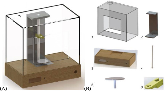
New design of electrospinning system. (A) Computer-aided design (CAD) model of electrospinning system proposed; (B) Main components:1 – acrylic box, 2 – acrylic support, 3 – cork base, 4 – teflon rod, 5 – collector, 6 – needle support.
In this new system, a significant number of non-conductive components were introduced. The box of the equipment (1) is made in acrylic, with a main hole to allow solvent evaporation. This structure incorporates a door to access to the equipment inner part and some additional entry spots to allow the entrance of the infusion tubes supplying the polymeric solution. The base of the equipment (3) is made in cork (Corecork TB40, Amorim, Portugal) due to its adequate mechanical resistance and machinability properties, insulation characteristics and eco-friendly nature. An acrylic part (2) is used to support the rod (4) made of teflon. The collector (5) is a grounded copper plate. The needle support (6) is made of acrylonitrile butadiene styrene (ABS) and slides on to adjust the distance between the needle (single or core/shell) and the collector. The collector (5) is static but its fixation system allows its easy replacement by other type of collectors. Items (1), (2), (4) and (5) were purchased and items (3) and (6) produced using a computer numeric control machine (CNC, from INAUTOM, Portugal) and an additive manufacturing system (Dimension machine from Stratasys). Additionally, the new system includes a syringe pump (model Pump 11 Elite, Harvard apparatus) to supply the polymeric solution, a polymeric tube connecting the syringe and the needle, a Liquid Crystal Display (LCD) to control the voltage, an emergency button and a high voltage source (model PS/ MJ30P0400-11, Glassman High Voltage, Inc).
The assembled electrospinning, which corresponds to a more versatile, flexible and user-friendly system, is shown in Figure 2. Key features of this system are:
Figure 2.
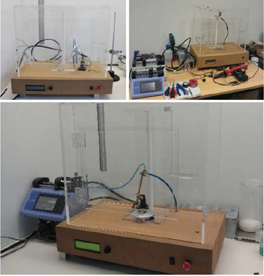
Assembled electrospinning apparatus
- Allowing the preparation of samples using vertical or horizontal configurations;
-Keeping the jet stable, not presenting secondary jets; due to the selection of non-conductive materials the jet is kept stable, and not presenting secondary jets;
-Providing accurate regulation of voltage due to the addition of a controller to the high voltage source.
2.2 Materials
Poly (e-caprolactone) (PCL) (Mw 50,000 (g/mol), bulk density: 1.1 g•cm-3) was kindly supplied by Perstorp (UK) and dissolved in dimethyl Ketone (DMK) (SigmaAldrich), and acetic acid (AA) (PanReac AppliChem). Gelatin powder from pig skin (type A, 300 bloom, 60 mesh) were kindly supplied by Italgelatine (Italy). For polymers dissolution, different solvents were explored as indicated in Table 1. In order to increase the conductivity of the solutions prepared with acetic acid, 2% v/v of triethylamine (TEA, Sigma Aldrich) was added. After optimization, 1,4-butanediol diglycidyl ether (BDDGE, Alpha Aesar, Germany) was used as the gelatin cross-linker.
Table 1.
Parameters tested to optimized the electrospun mesh production
| Polymer | Solution parameters | Processing parameters | |||
|---|---|---|---|---|---|
| Solvent system | Polymer concentration (wt%) | Distance between collector and needle (cm) | Voltage (kV) | Flow rate (mL/h) | |
| PCL | AA/TEA (2% v/v) DMK | 6, 11, 17 | 7, 10, 12 | 7, 10, 12 | 0.72, 3.17 |
| Gelatin | AA/TEA(2% v/v) | 5, 10, 15 | 0.40, 0.72 | ||
2.3 Electrospinning of Nanofiber Meshes
Polymeric meshes were processed using a single jet approach. Table 1 presents the processing parameters used to produce the meshes. Non-woven electrospun meshes were obtained at room temperature and relative humidity of 40%-50%. Crosslinking of electrospun gelatin fibers were produced through the incorporation of BDDGE on the gelatin solution immediately before fiber electrospinning to avoid the loss of configuration that is induced through a crosslinking bath after fiber production.
2.4 Physico-chemical Characterization
2.4.1 Morphology and Fiber Diameter
The morphology of the produced meshes was examined by scanning electron microscopy (SEM) using a Quanta 400 FEG ESEM/EDAX Genesis X4M (FEI Company, USA). Prior to examination, samples were coated with a gold/palladium (Au/Pd) thin film, by sputtering, using the SPI module sputter coater equipment. SEM images were also used to measure the fiber diameter using ImageJ software. For each condition, three individual samples were analyzed and fifty measurements per image were carried out.
2.4.2 Structure
Fourier transform infrared (FTIR) spectroscopy with attenuated total reflectance (ATR) was used to evaluate the chemical composition of the materials and to detect possible structural changes. FTIR analyses were carried out using an Alpha-P Brucker FTIR-ATR spectrometer, in the range of 4000-500 cm-1, at a 4 cm-1 resolution with 64 scans.
2.5 In Vitro Studies
Human dermal neonatal fibroblasts (hDNF) isolated from the foreskin of healthy male newborns (ZenBio, US) were cultured, expanded, and maintained in Dulbecco’s modified eagle medium (DMEM) (Gibco, US), at 37 °C in a humidified atmosphere of 5% CO2. The culture medium was changed twice a week and cells were trypsinized (0.25% trypsin/0.05% ethylenediaminetetraacetic acid (EDTA)/0.1% glucose in PBS (pH 7.5)) when they reached 70%-80% of confluence. Cells from passages between 8 and 11 were used in this study.
To assess cytotoxicity, electrospun meshes were tested in direct (samples) and indirect (leachables) contact with different pre-conditions (washed and non-washed in ultrapure water). Samples were sterilized with UV light followed by washing during 24 hours. hDNF cells were seeded in culture wells for 24 hours at a density of 2×10⁴ cells/well. Twenty-four hours later, samples (direct contact) and culture medium in contact with samples (indirect contact) were incubated with cells for another 24 hours. The culture medium was then removed from the wells and fresh basal medium with 20% v/v resazurin (Sigma-Aldrich) was added. Cells were incubated (37 °C, 5% v/v CO2) for an additional period of 2 hours, after which 300 μL per well were transferred to a black 96-well plate and measured (Ex at 530 nm, Em at 590 nm) using a micro-plate reader (Synergy MX, BioTek, US). The control consisted in cells alone.
For the quantification of the total double-stranded DNA (dsDNA) content, the cell pellets were recovered from the wells and washed with phosphate-buffered saline (PBS). The suspension was then centrifuged (10,000 rpm, 5 min) and then stored at -20 °C until further analysis. The dsDNA quantification was performed using the Quant-iT PicoGreen dsDNA assay kit (Molecular Probes, Invitrogen, US), according to the manufacturer’s protocol. Briefly, the samples were thawed and lysed in 1% v/v Triton X-100 (in PBS) for 1 hour at 250 rpm at 4 °C. Then, they were transferred to a black 96-well plate with clear bottom (Greiner) and diluted in Tris-EDTA (TE) buffer (200 mmol/L Tris-HCl, 20 mmol/L EDTA, pH 7.5). Finaly, samples were incubated for 5 min at room temperature in the dark, and fluorescence was measured using a microplate reader (Ex at 480, Em at 520 nm).
2.6 Statistical Analyses
All data points were expressed as mean ± standard deviation (SD). Statistical analysis (Levene’s and t-test) was carried out using IBM SPSS Statistics 20.0 with 99% confidence level for cytotoxicity assays. The results were considered statistically significant when p < 0.05.
3. Results and Discussion
3.1 Microscopic and Macroscopic Characterization of Electrospun Meshes
SEM images of the different produced meshes are presented in Figure 3 and Figure 4. For simplicity, only the tested conditions that resulted in fibers without beads or drops are presented in these figures.
Figure 3.
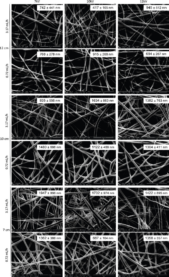
Electrospun PCL meshes (17 wt%, dissolved in DMK) obtained using different flow rates, distances between needle and collector and voltage. For each mesh, it is presented the average fiber diameter. Scale bar: 20 μm.
Figure 4.
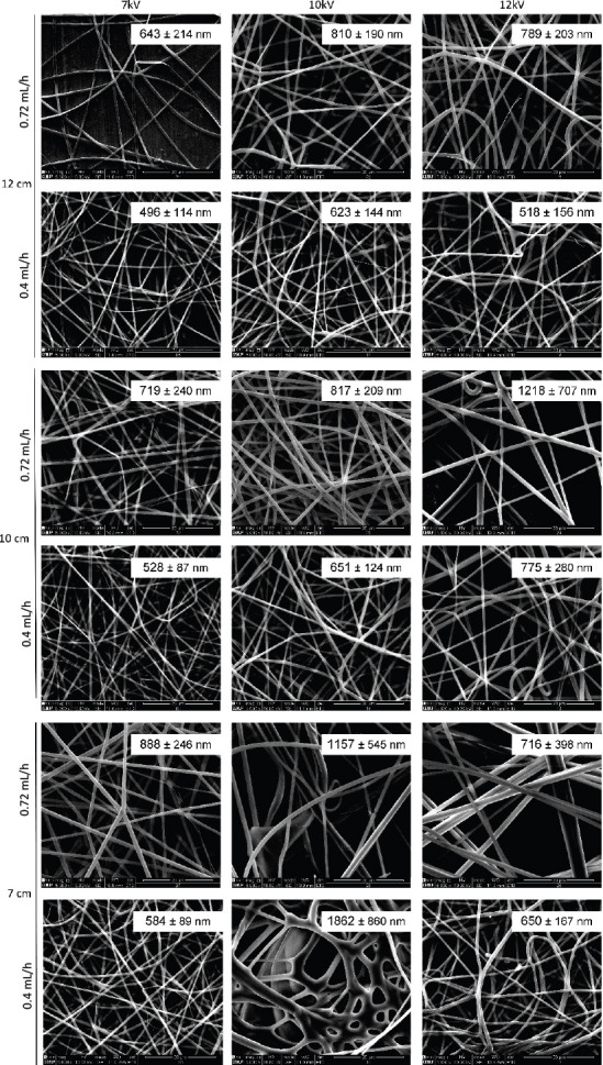
Electrospun gelatin meshes (15 wt%, dissolved AA/TEA 2% v/v) obtained using different flow rates, distances between needle and collector and voltage. For each mesh it is presented the average fiber diameter. Scale bar: 20 μm.
Results show that a stronger electric field increased the amount of produced fibers per time, which is correlated to the higher amount of charges into the solution, thereby increasing the jet velocity and, consequently, supplying more solution to the collector. The distance between the needle tip and the collector also determines the fiber diameter. By increasing this distance, the flight time is longer, allowing the solvent to evaporate, resulting in higher polymer chain stretching, which leads to a decrease in fiber diameter. These results show that the designed electrospinning is able to process proper meshes, being particularly relevant the production of gelatin meshes, which is strongly affected by ambient parameters, namely the relative humidity.
Concerning the PCL and gelatin meshes, according to the parameters tested significant differences were observed in terms of fiber diameter or morphology. Thus, for further analyses, the following requirements were selected, providing (i) longer distance to promote solvent evaporation and high chain stretching, (ii) high density of fibers per area, requiring less production time and (iii) continuous and uniform fiber production enhancing mechanical performance. Therefore, the followi ng fiber production parameters were selected: 17 wt% of PCL dissolved in DMK, produced with a flow rate of 3.17 mL/h, 12 cm distance between needle and collector and 10 kV of voltage; 15 wt% of gelatin dissolved in AA and 2% v/v of TEA, produced with a flow rate of 0.4 mL/h, a 12 cm distance between needle and collector and 12 kV of voltage. Moreover, as gelatin is a water-soluble protein, a crosslinking is needed to improve its mechanical properties and to increase its stability in aqueous medium[18]. Gelatin fibers were in situ crosslinked with BDDGE, according a protocol previously established[19]. The morphology of selected meshes is shown in Figure 5A-C. The fiber diameter measurements, the reduced standard deviation observed and the homogeneity of the obtained fibers demonstrates the stability of the system in producing nanoscale meshes. From Figure 5E, it is also possible to observe that the developed system improves fiber deposition in the collector.
Figure 5.
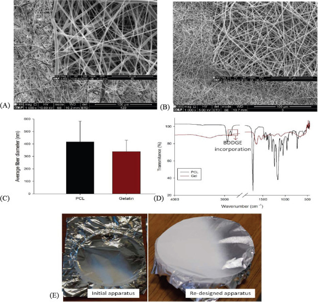
Characterization of PCL and gelatin electrospun meshes selected for further analysis. (A) Fiber morphology with 1000 × and 5000 × magnifications of PCL meshes; (B) Fiber morphology with 1000 × and 5000 × magnifications of gelatin meshes crosslinked with BDDGE; (C) Comparison between PCL and gelatin average fiber diameter; (D) FTIR spectra of PCL and crosslinked gelatin and (E) Influence of the purpose electrospinning system on fiber deposition over the collector in comparison with initial one comprising a significant metallic components.
FTIR-ATR spectra, used to evaluate possible structural changes in the electrospun meshes, are shown in Figure 5D. The spectrum of PCL meshes presents a 1720.7 cm-1 peak, corresponding to the C=O bond, characteristic to esters, and additional peaks between 750 and 1500 cm-1, corresponding to the CH2 groups of PCL chain. Two other peaks at 2863.69 cm-1 and 2941.57 cm-1 can also be observed, corresponding to the CH bonds. The FTIR spectrum of gelatin shows prominent peaks in four different amide regions, namely at 1700–1600 cm-1, corresponding to amide I; 1565–1520 cm-1, corresponding to amide II; 1240–670 cm-1, corresponding to amide III; and 3500–3000 cm-1, corresponding to amide A. The absorption of amide I contains contributions from the C=O stretching vibration of amide group and a minor contribution from the C-N stretching vibration. Amide II absorption is related to N-H bending and C-N stretching vibrations. Amide III presents vibrations from C-N stretching attached to N-H in-bending with weak contributions from C-C stretching and C=O in-plane bending. At 2930 and 2890 cm-1, it is possible to observe two peaks associated to the contribution of aliphatic moieties from BDDGE, confirming the incorporation of BDDGE into the gelatin matrix (Figure 5D). For both samples, no solvent residues were detected and no structural changes were observed.
3.2 Cytotoxicity of Nanofibers Produced
Cytotoxicity of the produced electrospun meshes system was assessed to demonstrate the process stability, as a stable jet allows to produce electrospun meshes without solvent deposition. According to the obtained results (Figure 6), fibroblasts cultured on the electrospun meshes remained metabolically active for both PCL and gelatin meshes. After 24 hours, no cytotoxicity was observed either in direct or indirect contact assays. In direct contact assays no statistical significance was observed between control and samples, meaning that the structures, when in contact with cells, does not induce any toxicity. Regarding indirect contact assay, no leachables delivered from the samples to the medium presented toxicity.
Figure 6.
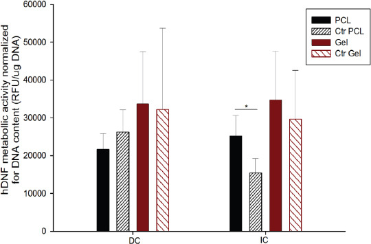
Cytotoxicity assay of PCL and gelatin electrospun meshes in direct contact (DC) and indirect contact (IC) with fibroblasts (hDNF cells), using as control cells seeded on the well. Statistical significance for p < 0.05 (*).
4. Conclusions
This paper introduces a solution electrospinning system developed to produce electrospun meshes for applications in tissue engineering and more specifically for wound dressing applications. For the fabrication of the electrospinning system non-conductive materials (cork and polymers) were used to replace metallic ones, allowing to obtain a feasible and versatile laboratory-scale apparatus with ability to produce reproducible nanofiber meshes from materials with distinct characteristics. The system was used to produce nanofibers from two distinct polymers, using two different solvents, demonstrating its versatility of the new reassembled apparatus. The fabrication of gelatin meshes is particularly relevant; as like other natural polymers, it is a material very sensitive to the environmental conditions, in particular the relative humidity. Keeping the processing parameters stable is key to obtain high quality and reproducible meshes, i.e., with no beads, resulting in filaments with constant diameter and in meshes with high porosity between pores. Meshes did not show any presence of remaining solvents, which can be correlated to the lack of toxicity detected through the biological assays.
The two selected materials are particularly relevant for skin applications. PCL presents high mechanical properties but, due to its hydrophobic nature, presents low interaction with cells. Contrary, gelatin displays many integrin-binding sites for cell adhesion, migration, proliferation, and differentiation due to the abundant Arg-Gly-Asp (RGD) amino acid sequences in its protein chain, which has been claimed to favor cell behavior. The combination of both materials may allow to produce meshes with improved properties.
Conflict of Interest and Funding
No conflict of interest was reported by the authors. This study was supported by the Project PTDC/BBB-ECT/2145/2014 and UID/Multi/04044/2013, financed by European Fonds Europeen de Developpement Regional (FEDER) through the Portuguese national programs Programa Operacional Factores de Competitividade (COMPETE), Portugal2020 and Norte2020, and by Portuguese funds through Funda?ao para a Ciencia e a Tecnologia (FCT). This work is also supported by a research grant (SFRH/BD/91104/2012) awarded to Juliana Dias by FCT.
Acknowledgements
The authors thank CEMUP, University of Porto for the SEM images.
References
- 1.Bartolo P, Kruth J-P, Silva J, et al. Biomedical production of implants by additive electro-chemical and physical processes. CIRP Annals —Manufacturing Technology. 2012;61(2):635–655. https://dx.doi.org/10.10167j.cirp.2012.05.005. [Google Scholar]
- 2.Teo W E, Ramakkrishna S. A review on electrospinning design and nanofibre assemblies. Nanotechnology. 2006;17(14):89–106. doi: 10.1088/0957-4484/17/14/R01. https://dx.doi.org/10.1088/0957-4484/17/14/R01. [DOI] [PubMed] [Google Scholar]
- 3.Ramakrishna S, Fujihara K, Teo W-E, et al. An Introduction to Electrospinning and Nanofibers. World Scientific; Singapore: 2005. [Google Scholar]
- 4.Rim N G, Shin C S, Shin H. Current approaches to electrospun nanofibers for tissue engineering. Biomedical Materials. 2013;8(1):014102. doi: 10.1088/1748-6041/8/1/014102. [DOI] [PubMed] [Google Scholar]
- 5.Bhardwaj N, Kundu S C. Electrospinning:A fascinating fiber fabrication technique. Biotechnology Advances. 2010;28(3):325–347. doi: 10.1016/j.biotechadv.2010.01.004. https://dx.doi.org/10.1016/j.biotechadv.2010.01.004. [DOI] [PubMed] [Google Scholar]
- 6.Niu H, Lin T. Fiber generators in needleless electrospinning. Journal of Nanomaterials. 2012;2012:1–13. https//dx.doi.org/10.1155/2012/725950. [Google Scholar]
- 7.Sill T J, von Recum H A. Electrospinning:Applications in drug delivery and tissue engineering. Biomaterials. 2008;29(13):1989–2006. doi: 10.1016/j.biomaterials.2008.01.011. https://dx.doi.org/10.1016/j.biomaterials.2008.01.011. [DOI] [PubMed] [Google Scholar]
- 8.Shin S H, Purevdori O, Castano O, et al. A short review: Recent advances in electrospinning for bone tissue regeneration. Journal of Tissue Engineering. 2012;3(1):1–11. doi: 10.1177/2041731412443530. https://dx.doi.org/10.1177/2041731412443530. [DOI] [PMC free article] [PubMed] [Google Scholar]
- 9.Nukavarapu S P, Kumbar S G, Merrell J G, et al. Laurencin C T, Nair L S. Nano-technology and Tissue Engineering: The Scaffold. 2nd edition. Taylor &Francis, London: 2014. Electrospun polymeric nanofibre scaffolds for tissue regeneration; pp. 229–254. [Google Scholar]
- 10.Li W J, Xia Y. Electrospinning of nanofibres:Reinventing the wheel? Advanced Materials. 2004;16(14):1151–1170. https://dx.doi.org/10.1002/adma.200400719. [Google Scholar]
- 11.IME Technologies n.d. IME Technologies: Your partner in electrospinning, viewed January 5. 2017 https://www.imetechnologies.com. [Google Scholar]
- 12.Inovenso, n.d. Inovenso, viewed January 8. 2017 http://inovenso.com/about/ [Google Scholar]
- 13.Elmarco, n.d. NanoSpiderTM Electrospinning Technology, viewed January 16, 2017. http://www.elmarco.com/electrospinning/electrospinning-technology/ [Google Scholar]
- 14.Har-el Y-E, Gerstenhaber J A, Brodsky R, et al. Electrospun soy protein scaffolds as wound dressings:Enhanced reepithelialization in a porcine model of wound healing. Wound Medicine. 2014;5:9–15. https://dx.doi.org/10.1016/j.wndm.2014.04.007. [Google Scholar]
- 15.Liu S-J, Kau Y-C, Chou C-Y, et al. Electrospun PLGA/collagen nanofibrous membrane as early-stage wound dressing. Journal of Membrane Science. 2010;355(1-2):53–59. https://dx.doi.org/10.1016/j.memsci.2010.03.012. [Google Scholar]
- 16.Gumu^derelioglu M, Dalkiranoglu S, Aydin R S T, et al. A novel dermal substitute based on biofunctionalized electrospun PCL nanofibrous matrix. Journal of Biomedical Materials Research Part A. 2011;98A(3):461–472. doi: 10.1002/jbm.a.33143. https://dx.doi.org/10.1002/jbm.a.33143. [DOI] [PubMed] [Google Scholar]
- 17.Dias J R, Granja P L, Bartolo P J. Advances in electrospun skin substitutes. Progress in Materials Science. 84:314. https://dx.doi.org/10.1016/j.pmatsci.2016.09.006. [Google Scholar]
- 18.Ward A G, Courts A. The Science and Technology of Gelatin. London: Academic Press, Inc., London; 1977. [Google Scholar]
- 19.Dias J R, Granja P L, Bartolo P J. Internal crosslinking evaluation of gelatin electrospinning fibers with 1,4-butanediol Diglycidyl ether (Bddge) for skin regeneration, in 10th World Biomaterials Congress, Montreal Canada, 1722 May. 20162016 https://dx.doi.org/10.3389/conf.FBI0E.2016.01.00896. [Google Scholar]


