

Abstract
A major limitation of using synthetic scaffolds in tissue engineering applications is insufficient angiogenesis in scaffold interior. Bioactive borate glasses have been shown to promote angiogenesis. There is a need to investigate the biofabrication of polymer composites by incorporating borate glass to increase the angiogenic capacity of the fabricated scaffolds. In this study, we investigated the bioprinting of human adipose stem cells (ASCs) with a polycaprolactone (PCL)/bioactive borate glass composite. Borate glass at the concentration of 10 to 50 weight %, was added to a mixture of PCL and organic solvent to make an extrudable paste. ASCs suspended in Matrigel were ejected as droplets using a second syringe. Scaffolds measuring 10 x 10 x 1 mm3 in overall dimensions with pore sizes ranging from 100 - 300 μm were fabricated. Degradation of the scaffolds in cell culture medium showed a controlled release of bioactive glass for up to two weeks. The viability of ASCs printed on the scaffold was investigated during the same time period. This 3D bioprinting method shows a high potential to create a bioactive, highly angiogenic three-dimensional environment required for complex and dynamic interactions that govern the cell’s behavior in vivo.
Keywords: bioprinting, biofabrication, human adipose-derived stem cell, MSCs, bioactive glass, polycaprolactone, scaffold, tissue engineering
1. Introduction
Dysfunctional or reduced blood supply is symptom of many health concerns, including diabetes, wound healing, and bone repair. Diabetes alone affects about 8.5% of the human population and costs the world over $376 billion in medical related expenses each year[1]. Another problem associated with reduced blood supply exists in bone grafts. Bone defects resulting from trauma, cancer, infection, or congenital skeletal abnormalities contribute to major surgeries performed every year. Autologous bone graft is still considered as the gold standard for most applications but creates donor site morbidity[2,3]. Allografts avoid these issues but have limited availability, concerns over immunogenicity, and potential disease transmission[4]. Several materials including biocompatible metals, bioceramics, and bio- polymers are currently being investigated as candidates for synthetic grafts. Additive manufacturing (AM), or popularly known as 3D printing, is a layer-by-layer material deposition process in which functional parts with complex shapes can be made which are otherwise difficult to manufacture. AM of biomaterials has shown that complex and strong implants can be made to treat different regions of bone, including load-bearing bone[5-7]. However, engineered bone scaffolds have not been as successful as au- tologous grafts thus far, largely due to insufficient vas- cularization and reduced biomechanical functiona[8-9]
The choices of materials and fabrication process are two significant factors that determine the success of engineered scaffolds. Many synthetic polymers and bioceramic materials have been used to make scaffolds for bone tissue engineering based on different AM techniques[10,11]. Since polymers are only bio- compatible, attempts have been made to improve their bioactivity by adding different bioceramics to make polymer composites. Typically, such composites are prepared by mixing an inorganic bioceramic material (in particle or fiber form) with a polymer which has been either heat melted or dissolved in an organic solvent[12]. The bioactivity of the eventual composite material not only depends on the choice of bioceramic (including bioactive glass, hydroxyapatite, etc.) but also depends on the method of composite preparation itself. Composite foams and films made by traditional fabrication methods such as solvent casting and particle leaching (SCPL) and thermally induced phase separation (TIPS) have reported improved water absorption and formation of hydroxyapatite[13]. However, it is difficult to control the scaffold porosity and shape using such methods. Scaffolds made with AM techniques such as selective laser sintering and ink-jet printing have also shown improved bioactivity, but incorporating cells during fabrication akin to bio- printing is not feasible due to processing limitations.
3D bioprinting is a process that fabricates a “living” construct in a layer-by-layer fashion using a “bio-ink” (cells suspended in a medium) with or without additional materials. Creation of a 3D environment with spatial arrangement of cells and materials is essential for vascularization and complete implant integration with the surrounding tissue. 3D bioprinting techniques can be broadly classified into three categories: (i) laser-assisted[14,15], (ii) inkjet-based[16], and (iii) extrusion-based printing[17]. Extrusion-based 3D bioprint- ing is the most successful biofabrication process to date with a range of materials compatible with the process[17,18]. In an extrusion-based bioprinting process, cells, hydrogels, and other materials are deposited using one or multiple syringes with a pressure system. The pressure system consists of either a mechanical piston or a pneumatic pressure source (mostly compressed air) that is computer controlled. The material is extruded through a nozzle tip and the process can deposit hydrogels with high cell density and minimal wastage in comparison to laser-assisted and ink-jet bioprinting techniques. Recent research has focused on creating living or cell-laden grafts for tissues including bone, cartilage, and skeletal musc- le[18-20]. In extrusion bioprinting, one syringe is typi- callly devoted to melt the polymer and deposit the melt for scaffolding structure. However, research to date has only considered the melt-deposition process to print scaffolding and is limited to low melting point polymers. Therefore, it is essential to investigate alternate approaches for printing other materials in order to develop more promising approaches in 3D bioprinting.
The addition of bioactive glass to a biocompatible polymer transforms the 3D environment with its dissolution products by up-regulating the cell-cell and cell-matrix interactions, which promotes vascularization. In the current study, we use a highly angiogenic bioactive 13-93B3 borate glass because of its osteo stimulatory/conductive nature and anti-microbial pro- perties[21]. In comparison to the more comm.on bioactive silicate glass, such as 45 S5 or 13-93 glass, 13- 93B3 has a higher reaction rate (5-10 times faster than silicate glasses) and resorbs (60 to 70% wt. loss) in a few days to weeks[9]. Ion release from the borate glass has been linked to the wound healing nature of this glass, with the boron ions in particular leading to the angiogenic effects, which are marginal in the silicate glasses[22]. The borate glass was recently approved by the Food and Drug Administration of the United States for human use with trade name Mirragen™ Advanced Wound Matrix.
Mesenchymal stem/progenitor cells (MSCs) have been used for cell therapy and in tissue engineering because of their ability to differentiate into multiple mesenchymal lineages in vitro, immune modulatory effects, and angiogenic capacity[23,24]. MSCs have been isolated from several tissues, including the bone marrow (BMSCs), adipose tissue (ASCs), and skin tis- sue[25-28]. The frequency of MSCs in adipose tissue is much higher than the more commonly studied source of bone marrow, yielding 100 to 500 times more cells per tissue volume[29-30]. ASCs have similar self-renewal abilities, common surface epitopes, growth kinetics, and cytokine expression profiles to BSCs. With the addition of ASCs, the scaffold is expected to improve its biomechanical and biological properties for better repair of the target tissue. In the current study, we investigate the feasibility of scaffold fabrication using a two syringe system with a PCL/borate glass composite dissolved in an organic solvent as a scaffold material, whilst simultaneously printing cells suspended in Matrigel, which is a gelatinous protein mixture representing basement membrane. Included in this study are the effect of borate glass content on the composite paste printability, the scaffold temporal bioactivity, its degradation in culture media, and ASC viability in the scaffold.
2. Materials and Methods
2.1 Preparation of PCL/13-93B3 Borate Glass Composite Material
Polycaprolactone (Sigma-Aldrich, St. Louis, Missouri, USA) was dissolved in chloroform (CF) (Sigma-Ald- rich, St. Louis, Misouri, USA) in a covered glass container with the help of a stirrer at ~5 0 °C. The PCL weight to CF volume ratio (grams:mL) was varied from 1:1 to 5:4 to determine the ideal ratio for printing. An appropriate ratio was established by visually inspecting the paste and through filament extrusion using a digital syringe dispenser (Loctite®, Henkel North America, Rocky Hill, Connecticut, USA). Then, 13-93B3 glass (Mo-Sci Corporation, Rolla, Missouri, USA) (nominal composition - 53% B2O3, 20% CaO, 12% K2O, 6% Na2O, 5% MgO, 4% P2O5 in weight percentage) with ~20 μm particle size was added to the PCL:CF mix in five different weight percentages in increments of 10, ranging from 10% to 50%. A magnetic stirrer was used to uniformly mix the composite paste, and no settling of the glass particle precipitate was observed before transferring the paste to a syringe. Each ratio was tested using a digital syringe dispenser at air pressure ranging from 10 to 50 psi and with nozzle tip diameter ranging from 110 to 600 μm (32 G to 20 G).
2.2 Preparation of Bio-ink
Frozen vials of approximately 1 x 10⁶ ASCs were obtained from three separate donors (LaCell, New Orleans, Louisiana, USA). Vials were unthawed, plated on 150 cm2 culture dishes (Nunc, Rochester, New York, USA) in 25 mL complete culture media (CCM), and incubated at 37 °C with 5% humidified CO2. The CCM contained 10% fetal bovine serum (Corning, Manassas, Virginia, USA), 1% 100x L-glutamine (GE Life Sciences, Logan, Utah, USA), 2% 100x antibio- tic/antimycotic (GE Life Sciences, Logan, Utah, USA, and minimum essential medium alpha modified (a-MEM) (Sigma-Aldrich, St. Louis, Missouri, USA). After 24 hours, the media was removed and adherent, viable cells were washed twice with PBS, harvested with 0.25% trypsin/1 mM EDTA (Gibco, Grand Island, New York, USA), and replated at 100 cells/cm2 in CCM. The media was changed every 3 to 4 days. For all experiments, sub-confluent cells (≤70% confluent) between passages 2 and 6 were used. To prepare the bio-ink, ASCs were suspended at a concentration of 10x106 cells per mL of Matrigel (Corning, Bedford, Massachusetts, USA) diluted to 9 mg/mL in phosphate buffered saline (PBS). The bio-ink was then transferred to a tapered nozzle tip (30G) which was stored on ice during the entire non-printing time. The bio-ink was gently pipetted to obtain a uniform distribution of cells just before printing. Matrigel was used in this work as it resembles the complex extra cellular environment found in many tissues.
2.3 Scaffold Fabrication
A square scaffold measuring 10 mm in length was printed with 0°-90° orientation of the filaments in alternate layers. The schematic in Figure 1A shows the printing set-up and Figre 1B depicts the printing process. A custom modified cartesian 3D printer (Geeetech, Prusa I3 A Pro) with two additional syringes controlled by digital dispensers was used for fabrication. The G-code for nozzle movement was written to print in a 0°-90° pattern to obtain rectangular pores. The printing parameters such as air pressure, filament spacing, layer height, and printing speed were identified based on visual inspection and optical microscopic images after the first and second layer printing for different paste compositions. To determine the printing parameters for Matrigel, an experiment was conducted by varying the nozzle tip distance from the glass slide, droplet dispensing time, and air pressure. Fluorescent images of the droplets were taken and ImageJ software was utilized to quantify the number of cells and cell distribution in each fluorescent image. A tapered nozzle tip (30 G) with 160 μm orifice provided the suitable droplet size (~400 μm) at 10 psi and 0.035 s dispensing time for deposition on the filament. While some droplets fell to the surrounding pores, most of the droplets stayed on the filament before the Matrigel was allowed to cross-link at room temperature. The fabrication experiments were performed at room temperature (64°F) where the variation in relative humidity (58-60%) was not considered to be a major factor.
Figure 1.
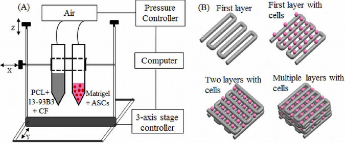
(A) Schematic of the printing set-up. One syringe contained PCL, 13-93B3 glass, and chloroform, while the other syringe contained ASCs suspended in Matrigel. (B) The composite layers are printed in 0°-90° pattern using one syringe while a second syringe prints the bio-ink droplets on top of every other layer.
2.4 Degradation of PCL/13-93B3 Glass Composite
The degradation of the PCL/13-93B3 composite was studied on scaffolds measuring (10x10x1) mm3. The printed scaffolds were dried at least for one day for complete evaporation of CF. Before immersion, the scaffolds were weighed and 300 mL of a-MEM was used for 1 g of the scaffold for soaking. Scaffolds were immersed in high density polyethylene (HD- PE) bottles containing a-MEM and stored in an incubator maintained at 37 °C for different time intervals ranging from 1 day to 14 days. After removal, the scaffold was gently washed with de-ionized (DI) water, and dried overnight. The dried scaffold was weighed to calculate the weight loss percentage. A sample size of three for each time interval was used in the study and the results were reported as mean ± standard deviation.
2.5 Cell Viability and Proliferation
The effect of chloroform evaporation from the scaffold on the viability of the ASCs was studied by depositing bio-ink droplets on the printed composite filaments. For this study, three composite layers were printed on a two-chamber microscope slide (Thermo Fischer Scientific, Rochester, New York, USA) and allowed to dry for ~2 mins before depositing a layer of bio-ink droplets. The Matrigel in bio-ink was allowed to polymerize at room temperature for 20 minutes, then 1 mL of CCM was added. The slides were then incubated at 37 °C with 5% humidified CO2 for three time intervals of 2 hrs, 1 week, and 2 weeks. The medium was changed every three days. After each time interval, the CCM was removed and the cells were stained using the Live/Dead Cell Imaging Kit (ref. R37601, Eugene, Oregon, USA), incubated for 15 minutes at room temperature and examined under a fluorescent microscope (Olympus IX51, Melville, New York, USA).
2.6 Scaffold Characterization
Optical microscopic images were used to measure the filament width and pore size with at least five measurements and the results were reported as mean ± standard deviation. Samples were sputter coated with gold/palladium (Au/Pd) for 60 s before performing scanning electron microscopy (SEM). SEM (Hitachi S-4700 FESEM, Hitachi Co., Tokyo, Japan) images were taken to evaluate the surface morphology of the scaffolds, internal structure of the filaments, and formation of hydroxyapatite-like material on the scaffold surface. Scans were run from 20 values ranging from 10° to 80° using Cu Ka radiation (X = 0.154056 nm) for X-ray diffraction (XRD) analysis (Philips X-Pert, Westborough, MA) on the as-received PCL, as-printed PCL/B3 glass scaffold, and the scaffold after a-MEM immersion to determine the changes in the crystalline/amorphous nature of the material.
3. Results
3.1 Fabrication of PCL/13-93B3 Glass Composite Scaffolds
The initial set of printing tests included depositing single layers using the composite paste with 10 wt. % of 13-93B3 glass. A minimum air pressure of 30 psi was required to extrude the paste through a 260 μm (25G) nozzle tip. Lam (25G) nozzle tip. Larger tips (>260 μm) resulted in thick filaments which took longer time (>5 min) to dry and smaller tips (<260 μm) consistently caused clogging issues. The roundness of the filament improved with increasing glass content along with the paste viscosity. The minimum air pressure required to extrude the paste increased when glass content was increased from 10 wt. % to 30 wt. %. At higher glass content (40 wt. % and 50 wt. %), the nozzle clogged during fabrication. Therefore, additional CF (about 1 mL) was added to the paste to reduce the viscosity for clog-free extrusion using the 25G tip. The 13-93B3 glass weight percentage and PCL: CF ratios used to make composite pastes are shown in Table 1. The final printing parameters used to fabricate the composite scaffolds containing 50 wt. % 13-93B3 glass content is also provided in Table 1.
Table 1.
PCL/13-93B3 glass paste compositions and printing parameters
| Composite | 13-93B3 Glass | PCL:CF | Final Printing Parameters |
|---|---|---|---|
| Paste # | (wt. %) | (g to mL) | (using C5 paste) |
| C1 | 10 | 5:3 | Printing speed - 8 mm/s |
| C2 | 20 | 5:3 | Dwell time - 2 min |
| C3 | 30 | 5:3 | Layer height - 0.1 mm |
| C4 | 40 | 5:4 | Air pressure - 30 psi |
| C5 | 50 | 5:4 | Nozzle tip - 260 μm |
A filament width of 397±10 p,m was measured for scaffolds printed with the C5 paste while average pore size is dependent on the filament spacing. A filament spacing of 600 μm provided square pores measuring ~160 μm (Figure 2A). In comparison, the average pore size was ~350 (xm for scaffolds fabricated with 800 (xm filament spacing. Figure 2B shows scaffolds fabricated with 800 (xm filament spacing. Warping was predominant while fabricating scaffolds with C1 and C2 pastes and this led to difficulty in printing after about 8 layers; see warped C1 and C2 scaffolds in Figure 2B. The warpage in scaffolds fabricated with C3 paste was less pronounced and a scaffold height of 0.8 mm (10 layers) was obtained. Overall, the best results were achieved for scaffolds fabricated with C5 paste as they were successfully printed to 1 mm height (12 layers). The scaffold fabricated with C5 paste had enough strength to be safely handled for subsequent degradation and in vitro assessment.
Figure 2.
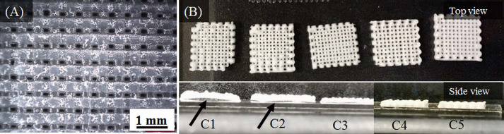
(A) Optical microscopic image showing the pores (~160 μm) in a composite scaffold fabricated with C5 paste. (B) Scaffolds fabricated with different composite pastes (C1 to C5). The bottom panel shows scaffold warpage with an arrow indicating space between scaffold and slide. Warpage was minimal in C3/C4 scaffolds and completely absent in C5 scaffolds.
SEM images of scaffolds fabricated with C5 paste are shown in Figure 3. Figures 3A and 3B show the surface morphology of the filament. Glass particles are conspicuously absent from the surface of filaments. No pores on the filament surface were detected even when observed at a 2000x magnification. Figures 3C and 3D show the filament cross-sectional surface. Glass particles dispersed in the PCL matrix can be seen in the interior. The dissolved PCL in chloroform encloses the glass particles and surface tension effects between the nozzle tip and PCL during extrusion appear to have caused the presence of only PCL on the surface.
Figure 3.
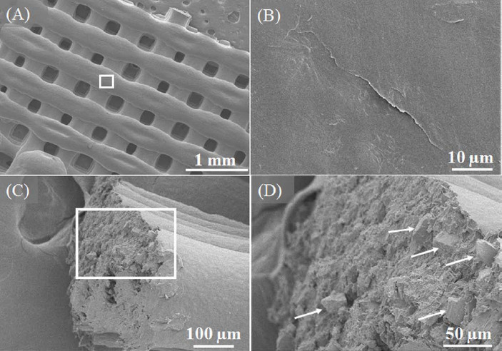
SEM images of the 50:50 PCL/13-93B3 glass scaffold. (A) Low magnification (30x) image of scaffold surface showing filaments and pores, (B) smooth surface morphology of filament (2000x magnified image of the region marked in (A), (C) fractured surface of a broken filament with PCL matrix and glass particles, (D) magnified image of the region marked in (C) with arrows indicating glass particles present a few microns beneath the surface.
3.2 Degradation and Bioactivity of PCL/13-93B3 Glass Composite
Recent studies suggest that cell culture medium can be used as an alternative to simulated body fluid (SBF) to evaluate the bioactivity of the materials, with no significant differences in the formation of hydroxyapatite (HA)[31]. We studied the degradation of the composite by soaking the scaffolds made with C5 paste in a-MEM for 1, 3, 7, and 14 days. The scaffold weight before and after immersion (post drying) was recorded at each time interval. No significant weight loss was observed for 3 days (less than 1%), and the measured weight loss was 10.7±5% at 7 days and 23.2±4% at 14 days. As PCL takes a longer time to degrade, the weight loss measured is due to the ionic dissolution of the 13-93B3 borate glass. Formation of flower like florets, which typically represent HA-like material, was observed on the filament surface as shown in Figures 4A and 4B.
Figure 4.
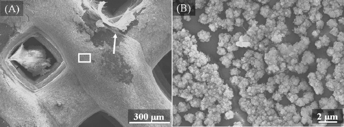
SEM images of the 50:50 PCL/13-93B3 glass scaffold after immersion in α-MEM for 14 days. (A) ~1 μm thick layer was formed on the filament surface (a piece of the reacted layer indicated by arrow raised to expose the polymer beneath), (B) magnified image (8000x) of the area marked in (A) showing the formation of HA-like florets on the filament.
The energy-dispersive X-ray spectroscopy (EDX) analysis indicated the presence of calcium (Ca), phosphorous (P), and oxygen (O) on the reacted surface of the scaffold after 14-day immersion in a-MEM. Figure 5A shows the result of the line scan performed on the surface indicating the changes in elemental composition in atomic weight percentage. In particular, carbon (C), Ca, P, and O are plotted to provide a better comprehension of the reacted surface. Signals of sodium (Na) and magnesium (Mg) were also detected but in very small amounts. All the signals correspond to K series emissions (Ka and Kp). The location of the scan region is shown by an arrow line in Figure 5B. The location was selected such that a scan line (~70 μm long) has to start on a reacted surface, pass through the exposed PCL surface, and end on the reacted surface. As signals were recorded, the presence of elements was confirmed. It can be observed that the percentage of Ca and P drops to zero and amount of O decreases as well when scanning the PCL surface (from ~30 μm to ~50 μm in Figure 5A). The presence of Ca, P, and O indicates that the glass has reacted and formed HA-like material on the scaffold surface.
Figure 5.
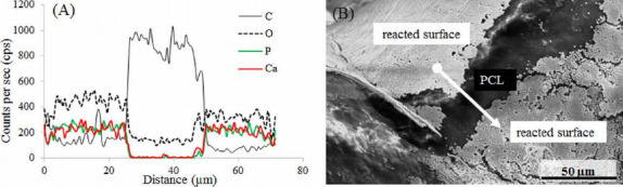
EDX analysis on the surface of the 50:50 PCL/13-93B3 glass scaffold soaked in α-MEM. (A) Graph of line scan data showing the variation in Ca, P, O, and C in atomic weight percentages; presence of Ca, P, and O on the reacted surface confirms the glass reaction and formation of HA-like material, (B) SEM image with the arrow line indicating the scanned area for EDX analysis.
3.3 Effect of Chloroform Evaporation on ASC Viability
The viability of ASCs was studied by performing a live/dead assay after incubating the samples for 24 hours, and 1 week. The viability of cells after 24 hours was 70±10% (Figures 6A and 6B). After 1 week, the viability of cells was 58±11% (Figures 6C and 6D).
Figure 6.
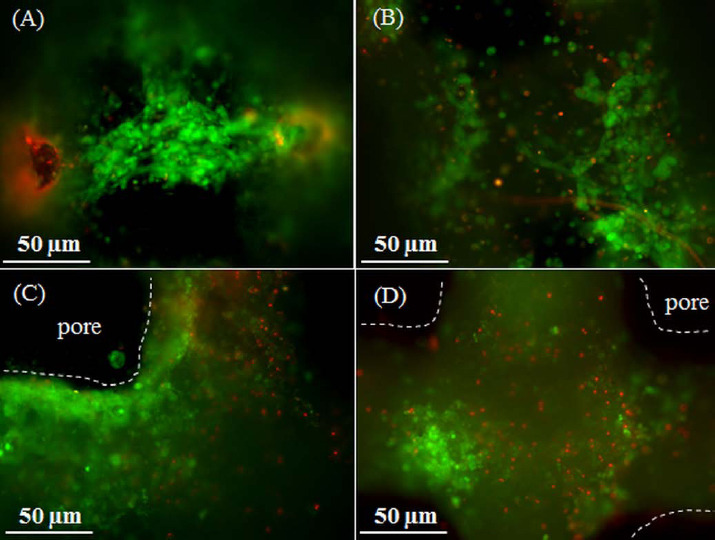
Live/Dead images of ASCs suspended in Matrigel and printed on the 50:50 PCL/13-93B3 glass composite scaffold. Imaged after (A-B) 24 hours, and (C-D) 1 week. The dotted lines indicate the outline of the filament and dark space indicates the pore.
4. Discussion
A variety of solvents are available to dissolve different biopolymers[32]. Extrusion of solvent dissolved polymer and bioactive glass is safe at r oom temperature and reduces the process complexity since there is no need for temperature control. This method can be adopted by most of the existing open-source 3D printers available in the market. Chloroform (CF) was used in this study because it provides: (i) a high viscosity paste, making it suitable for extrusion-based 3D printing, (ii) fast evaporation (~2 min), making it safe to print ASCs in Matrigel during the fabrication process, (iii) filament porosity for accelerated glass dissolution to the surrounding, and (iv) faster polymer bulk degradation by exposing the interior of filament. To address the issue of safety with the use of CF while depositing bio-ink, we performed cell viability study on scaffolds made with C3 (30% glass) and C5 (50% glass) composite pastes using a live/dead assay. The results showed healthy living ASCs on PCL/13- 93B3 glass filaments even after one week of incubation.
An important aspect in extrusion bioprinting is to create a scaffolding structure that supports cells and provides shape and mechanical integrity. Extrusion bioprinters typically have more than one syringe, with one of the syringes devoted to print scaffolding structure. The options utilized for this purpose include melt-deposition of polymer and fused deposition modeling (FDM) with a polymer wire feed. Because of high temperatures involved in many melting bio- polymers such as polylactic acid (PLA, with a melting point of 160 °C), PCL has become one of the most widely used polymers owing to its lower melting point of 60 °C. For 3D printing, PCL is an attractive option because of its good rheological and viscoelastic properties. Despite its slow degradation rate (~2 years depending on the molecular weight), PCL has been widely used to fabricate scaffolds for bone tissue engineering[33]. But for other tissue engineering applications which require faster degrading of scaffolding structure, this may become an impediment. Since FDM fabricated polymer scaffolds are only biocompatible, another issue would be to make the scaffolding structure bioactive by incorporating bioceramic materials. In the past, some researchers made a polymer-bioactive glass wire for use by the FDM process to fabricate polymer-bioactive glass scaffolds[34]. However, no significant improvement in bioactivity and cell growth has been reported, which could be due to inadequate ionic dissolution of the glass into the surrounding environment. This makes the FDM and melt-deposition options unattractive for fabrication of polymer-glass composite scaffolds. In our current study, polymer (PCL) was dissolved in a s olvent (chloroform), mixed with a bioactive glass (13-93B3 glass), and then extruded to fabricate the scaffold. Our weight loss results showed that most of the 13-93B3 glass has reacted in 2 weeks. The schematic in Figure 7 explains the difference in the glass dissolution from filaments printed using (A) FDM or melt-extrusion process and (B) solvent-based extrusion process. Fine cracks on the filament surface which are a couple of microns wide and up to ten microns or more in length can be observed in Figure 7C. Those cracks are believed to aid glass dissolution when the scaffold is immersed in the culture medium.
Figure 7.
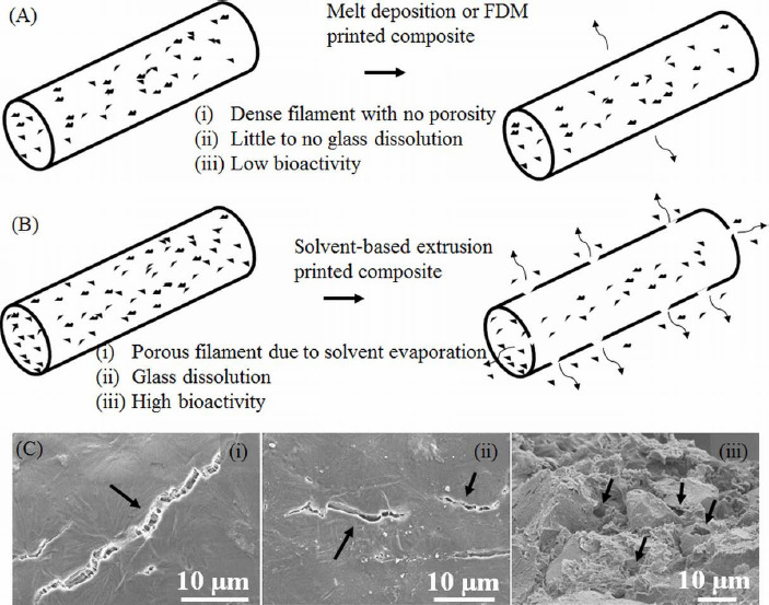
Schematic highlighting the difference in two methods of extrusion printing. (A) Melt-deposition of polymer-glass composite resulting in a dense filament and low bioactivity, (B) solvent-based extrusion printed composite resulting in a porous filament with high bioactivity, (C) SEM images showing surface cracks on the filament indicated by arrows in (i) and (ii), and pores inside the filament measuring less than 10 μm are also indicated by arrows in (iii).
Our degradation results also show a controlled release of 13-93B3 glass over a period of two weeks into the surrounding solution. In the past, composite thin films have been made using PCL/13-93B3 glass and PCL/45S5 glass with different amount of glass content[35]. The degradation data of such thin films indicate that the entire glass almost completely dissolves in about three days. The graph shown in Figure 8 compares the weight loss percentage of the PCL/13-93B3 glass thin films (80 μm) with that of the current study. Almost entire 13-93B3 glass was reacted in about 3 days from thin films. The faster degradation in composite films could be due to the thickness of the film. The scaffolds in the current study are made by filaments which are about 400 μm in diameter and have no surface pores that explained the very little glass dissolution in three days. However, the water absorbing potential of polymers in general was reportedly found to improve after the addition of bioceramic filler materials such as HA and even bioactive glass[12]. In our study, the glass dissolution increased significantly after 7 and 14 days, which is believed to be due to the internal porosity of the filament created after the CF evaporation and also glass dissolution creating more porosity. The entire B2O3 present in the borate glass (53 B2O3, 20 CaO, 12 K2O, 6 Na2O, 5 MgO, 4 P2O5 in composition by weight %) completely dissolves into surrounding environment, and the rest oxides with the exception of MgO participate in the formation of HA. By neglecting the weight of HA formed, it can be theoretically calculated that there is about ~35% weight loss for the scaffold, assuming a complete 13-93B3 glass dissolution in 50:50 PCL/13-93B3 composite. In this study, the weight loss for 50:50 PCL/13-93B3 compositescaffold was ~23%, indicating that ~70% of the 13-93B3 glass present in the scaffold had reacted in 14 days. This degradation vs. time characteristic can be used to develop a controlled degradation of 3D scaffold that is beneficial in certain tissue engineering applications, especially in drug delivery.
Figure 8.
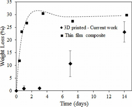
Weight loss percentage comparison of 3D printed 50:50 PCL/13-93B3 glass composite scaffolds vs. thin film composite made using PCL, CF, and 50% 13-93B3 glass[35].
The reacted layer formed on the scaffold surface was ~1 μm thick and not completely uniform (dense collection of florets can be seen in Figure 4C). XRD analysis was performed to confirm the presence of crystalline HA but the XRD pattern obtained on a 14 day soaked scaffold could not match the known HA crystalline peak. This is believed to be because of formation of amorphous HA or non-stoichiometric HA, which is not uncommon in such cases. Figure 9 shows XRD patterns of the as-received 13-93B3 glass, PCL/13-93B3 glass composite scaffold, and the composite scaffold after soaking in a-MEM for 2 weeks. The semi-crystalline nature of the PCL was confirmed with characteristic peaks (marked by *) and amorphous profile of 13-93B3 glass with no sharp peaks and characteristic hump can be observed in the XRD patterns shown in Figure 9. There are additional peaks observed for the α-MEM soaked sample which could not be identified to a known material in the database (marked by †). However, the typical amorphous hump seen in glass was not existent in the soaked sample, indicating that most of the 13-93B3 glass in the scaffold has reacted after 14 days.
Figure 9.
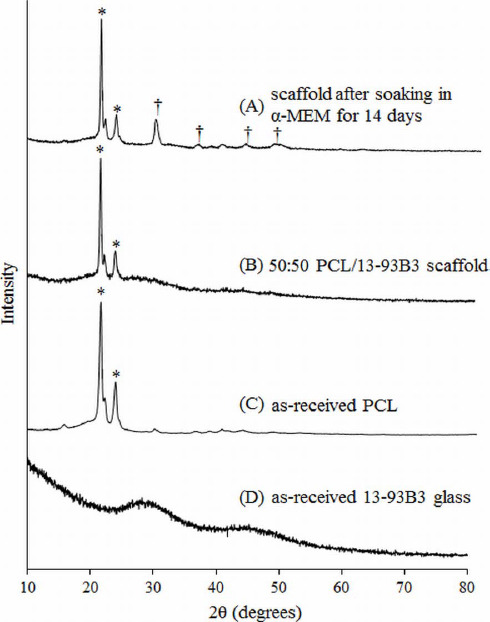
XRD patterns of (A) 50:50 PCL/13-93B3 glass composite scaffold soaked in α-MEM for 14 days, (B) PCL/13-93B3 glass scaffold, (C) as-received PCL showing a semi-crystalline nature with characteristic peaks marked by *, and (D) as-received 13-93B3 glass with characteristic amorphous hump (25° to 35° and 40° to 50°).
It is known that pore size is an important parameter of the scaffold that could potentially affect the bone growth after implantation, and it has been reported that pore size in the range of 100 to 300 μm is beneficial for bone growth[9]. The scaffolds we fabricated have pores in this range. Moreover, the ASCs when co-cultured with 2.5 mg of 13-93B3 glass per 1 mL of culture media in standard culture conditions show osteogenic differentiation with no detrimental effects. Therefore, the scaffolds fabricated using solvent-based extrusion 3D bioprinting developed as in the present study have a high potential for non-load-bearing bone repair applications.
5. Conclusion
This study investigated the feasibility of fabricating a scaffold with polycaprolactone/bioactive borate glass composite using a solvent based extrusion 3D printer integrated with printing of human ASCs suspended in Matrigel during the scaffold fabrication process. Printing process parameters were identified for the composite and bio-ink to fabricate a (10×10×1) mm3 ASC-laden scaffold with pore sizes ranging from 100 to 300 μm suitable for bone tissue engineering. In comparison to the conventional melt-deposition extrusion 3D bioprinting, the degradation of polymer/bioactive glass scaffolds showed a c ontrolled release of bioactive glass with ~23% weight loss in two weeks. Formation of hydroxyapatite-like crystals on the surface of the scaffold after soaking in culture media for up to two weeks shows the strong bioactivity of the fabricated composite scaffold and its high potential for bone repair. The live/dead assay showed more than 60% viable ASCs on the scaffold after 1 week of incubation, with minimal negative effects from chloroform evaporation on the cells. The results of this study show the high potential of the solvent-based extrusion 3D bioprinting process to fabricate a scaffold with cells and polymer composites for tissue engineering applications.
Conflict of Interest and Funding
No conflict of interest was reported by the authors.
Acknowledgment
The glass used in this study was provided by MO-SCI Corporation, Rolla, Missouri, USA. The authors thank Mariahe Long for her assistance during experiments and imaging.
References
- 1.Zhang P, Zhang X, Brown J B, et al. Economic impact of diabetes. IDF Diabetes Atlas 2010 [Google Scholar]
- 2.Banwart J C, Asher M A, Hassanein R S. Iliac crest bone graft harvest donor site morbidity. A statistical evaluation. Spine (Phila. Pa. 1976) 1995;20(9):10551060. doi: 10.1097/00007632-199505000-00012. https://doi.org/10.1097/00007632-199505000-00012. [DOI] [PubMed] [Google Scholar]
- 3.Goulet J A, Senunas L E, DeSilva G L, et al. Autogenous iliac crest bone graft. Complications and functional assessment. Clinical Orthophopedics and Related Research. 1997;(339):76–81. doi: 10.1097/00003086-199706000-00011. https://doi.org/10.1097/00003086-199706000-00011. [DOI] [PubMed] [Google Scholar]
- 4.Giannoudis P V, Dinopoulos H, Tsiridis E. Bone substitutes: an update. Injury. 2005;36(3):S20–S27. doi: 10.1016/j.injury.2005.07.029. http://dx.doi.org/10.1016/j.injury.2005.07.029. [DOI] [PubMed] [Google Scholar]
- 5.Doiphode N D, Huang T, Leu M C, et al. Freeze extrusion fabrication of 13-93 bioactive glass scaffolds for bone repair. Journal of Materials Science:Materials in Medicine. 2011;22(3):515–523. doi: 10.1007/s10856-011-4236-4. http://dx.doi.org/10.1007/s10856-011-4236-4. [DOI] [PubMed] [Google Scholar]
- 6.Kolan K C R, Leu M C, Hilmas G E, et al. Effect of material, process parameters, and simulated body fluids on mechanical properties of 13-93 bioactive glass porous constructs made by selective laser sintering. Journal of Mechanical Behaviour of Biomedical Materials. 2012;13:14–24. doi: 10.1016/j.jmbbm.2012.04.001. http://dx.doi.org/10.1016/jjmbbm.2012.04.001. [DOI] [PubMed] [Google Scholar]
- 7.Bartolo P, Kruth J P, Silva J, et al. Biomedical production of implants by additive electro-chemical and physical processes. CIRP Annals —Manufacturing Technology. 2012;61(2):635–655. http://dx.doi.org/10.1016/jxirp.2012.05.005. [Google Scholar]
- 8.Temple J P, Hutton D L, Hung B P, et al. Engineering anatomically shaped vascularized bone grafts with hASCs and 3D-printed PCL scaffolds. Journal of Biomedical Materials Research Part A. 2014;102(12):4317–4325. doi: 10.1002/jbm.a.35107. http://dx.doi.org/10.1002/jbm.a.35107. [DOI] [PubMed] [Google Scholar]
- 9.Rahaman M N, Day D E, Sonny Bal B, et al. Bioactive glass in tissue engineering. Acta Biomaterialia. 2011;7(6):2355–2373. doi: 10.1016/j.actbio.2011.03.016. http://dx.doi.org/10.1016/j.actbio.2011.03.016. [DOI] [PMC free article] [PubMed] [Google Scholar]
- 10.Liu X, Ma P X. Polymeric scaffolds for bone tissue engineering. Annals Biomedical Engineering. 2004;32(3):477–486. doi: 10.1023/b:abme.0000017544.36001.8e. http://dx.doi.org/10.1023/B:ABME.0000017544.36001.8e. [DOI] [PubMed] [Google Scholar]
- 11.Bose S, Vahabzadeh S, Bandyopadhyay A. Bone tissue engineering using 3D printing. Materials Today. 2013;16(12):496–504. http://dx.doi.org/10.1016/j.mattod.2013.11.017. [Google Scholar]
- 12.Puska M, Aha A J, Vallittu P. Polymer composites for bone reconstruction. Advances in Composite Materials - Analysis of Natural Man-Made Materials. 2011:55–72. http://dx.doi.org/10.5772/20657. [Google Scholar]
- 13.Rezwan K, Chen Q Z, Blaker J J, et al. Biodegradable and bioactive porous polymer/inorganic composite scaffolds for bone tissue engineering. Bio-materials. 2006;27(18):3413–3431. doi: 10.1016/j.biomaterials.2006.01.039. http://dx.doi.org/10.1016/j.biomaterials.2006.01.039. [DOI] [PubMed] [Google Scholar]
- 14.Guillotin B, Souquet A, Catros S, et al. Laser assisted bioprinting of engineered tissue with high cell density and microscale organization. Biomaterials. 2010;31(28):7250–7256. doi: 10.1016/j.biomaterials.2010.05.055. http://dx.doi.org/10.1016/j.biomaterials.2010.05.055. [DOI] [PubMed] [Google Scholar]
- 15.Yan J, Huang Y, Chrisey D B, et al. Laser-assisted printing of alginate long tubes and annular constructs. Biofabrication. 2013;5(1):15002. doi: 10.1088/1758-5082/5/1/015002. http://dx.doi.org/10.1088/1758-5082/5Z1/015002. [DOI] [PubMed] [Google Scholar]
- 16.Chang C C, Boland E D, Williams S K, et al. Direct-write bioprinting three-dimensional biohybrid systems for future regenerative therapies. Journal of Biomedical Materials Research Part B: Applied Bio- materials. 2011;98B(1):160–170. doi: 10.1002/jbm.b.31831. http://dx.doi.org/10.1002/jbm.b.31831. [DOI] [PMC free article] [PubMed] [Google Scholar]
- 17.Ozbolat I T, and Hospodiuk M. Current advances and future perspectives in extrusion-based bioprinting. Biomaterials. 2016;76:321–343. doi: 10.1016/j.biomaterials.2015.10.076. http://dx.doi.org/10.1016/j.biomaterials.2015.10.076. [DOI] [PubMed] [Google Scholar]
- 18.Murphy S V, Atala A. 3D bioprinting of tissues and organs. Nature Biotechnology. 2014;32(8):773–785. doi: 10.1038/nbt.2958. http://dx.doi. org/10.1038/nbt.295 8. [DOI] [PubMed] [Google Scholar]
- 19.Kang H-W, Lee S J, Ko I K, et al. A 3D bioprinted complex structure for engineering the muscle-tendon unit. Biofabrication. 2015;7(3):35003. doi: 10.1088/1758-5090/7/3/035003. http://dx.doi.org/10.1088/1758-5090/7/3/035003. [DOI] [PubMed] [Google Scholar]
- 20.Wu Z, Su X, Xu Y, et al. Bioprinting three-dimensional cell-laden tissue constructs with controllable degradation. Science Reports. 2016;6:24474. doi: 10.1038/srep24474. http://dx.doi.org/10.1038/srep24474. [DOI] [PMC free article] [PubMed] [Google Scholar]
- 21.Lin Y, Brown R F, Jung S B, et al. Angiogenic effects of borate glass microfibers in a rodent model. Journal of Biomedical Materials Research Part A. 2014;102(12):4491–4499. doi: 10.1002/jbm.a.35120. http://dx.doi.org/10.1002/jbm.a.35120. [DOI] [PubMed] [Google Scholar]
- 22.Jung S B, Day D E. Revolution in wound care?Inexpensive, easy-to-use cotton candy-like glass fibers appear to speed healing in initial venous stasis wound trial. The American Ceramic Society Bulletin. 2011;90(4):25–29. [Google Scholar]
- 23.Salem H K, Thiemermann C. Mesenchymal stromal cells: current understanding and clinical status. Stem Cells. 2009;28(3):585–596. doi: 10.1002/stem.269. http://dx.doi.org/10.1002/stem.269. [DOI] [PMC free article] [PubMed] [Google Scholar]
- 24.Wu Y, Chen L, Scott P G, et al. Mesenchymal stem cells enhance wound healing through differentiation and angiogenesis. Stem Cells. 2007;25(10):2648–2659. doi: 10.1634/stemcells.2007-0226. http://dx.doi.org/10.1634/stemcells.2007-0226. [DOI] [PubMed] [Google Scholar]
- 25.De Ugarte D A, Morizono K, Elbarbary A, et al. Comparison of multi-lineage cells from human adipose tissue and bone marrow. Cells Tissues Organs. 2003;174(3):101–109. doi: 10.1159/000071150. http://dx.doi.org/10.1159/000071150. [DOI] [PubMed] [Google Scholar]
- 26.Izadpanah R, Trygg C, Patel B, et al. Biologic properties of mesenchymal stem cells derived from bone marrow and adipose tissue. Journal of Cellular Biochemistry. 2006;99(5):1285–1297. doi: 10.1002/jcb.20904. http://dx.doi.org/10.1002/jcb.20904. [DOI] [PMC free article] [PubMed] [Google Scholar]
- 27.Wagner W, Wein F, Seckinger A, et al. Comparative characteristics of mesenchymal stem cells from human bone marrow, adipose tissue, and umbilical cord blood. Experimental Hematology. 2005;33(11):14021416. doi: 10.1016/j.exphem.2005.07.003. http://dx.doi.org/10.1016/j.exphem.2005.07.003. [DOI] [PubMed] [Google Scholar]
- 28.Sakaguchi Y, Sekiya I, Yagishita K, et al. Comparison of human stem cells derived from various mesenchymal tissues: superiority of synovium as a cell source. Arthritis Rheumatology. 2005;52(8):2521–2529. doi: 10.1002/art.21212. http://dx.doi.org/10.1002/art.21212. [DOI] [PubMed] [Google Scholar]
- 29.D'Andrea F, De Francesco F, Ferraro G A, et al. Large-scale production of hum an adipose tissue from stem cells:a new tool for r egenerative medicine and tissue banking. Tissue Engineering Part C Methods. 2008;14(3):233–242. doi: 10.1089/ten.tec.2008.0108. http://dx.doi.org/10.1089/ten.tec.2008.0108. [DOI] [PubMed] [Google Scholar]
- 30.Casteilla L, Dani C. Adipose tissue-derived cells:from physiology to regenerative medicine. Diabetes &Metabolism. 2006;32(5 Pt 1):393–401. doi: 10.1016/s1262-3636(07)70297-5. http://dx.doi.org/DM-11-2006-32-5-1262-3636-101019-200519820. [DOI] [PubMed] [Google Scholar]
- 31.Lee J T Y, Leng Y, Chow K L, et al. Cell culture medium as an alternative to conventional simulated body fluid. Acta Biomaterialia. 2011;7(6):2615–2622. doi: 10.1016/j.actbio.2011.02.034. http://dx.doi.org/10.1016/j.actbio.2011.02.034. [DOI] [PubMed] [Google Scholar]
- 32.Miller-Chou B A, Koenig J L. A review of polymer dissolution. Progress in Polymer Science. 2003;28(8):1223–1270. http://dx.doi.org/10.1016/S0079-6700(03)00045-5. [Google Scholar]
- 33.Woodruff M A, Hutmacher D W. The return of a forgotten polymer —polycaprolactone in the 21st century. Progress in Polymer Science. 2010;35(10):12171256. http://dx.doi.org/10.1016/j.progpolymsci.2010.04.002. [Google Scholar]
- 34.Korpela J, Kokkari A, Korhonen H, et al. Biodegradable and bioactive porous scaffold structures prepared using fused deposition modeling. Journal of Biom- edical Materials Research Part B:Applied Biomaterials. 2013;101B(4):610–619. doi: 10.1002/jbm.b.32863. http://dx.doi.org/10.1002/jbm.b.32863. [DOI] [PubMed] [Google Scholar]
- 35.Mohammadkhah A, Marquardt L M, Sakiyama-Elbert S E, et al. Fabrication and characterization of poly-(s)-caprolactone and bioactive glass composites for tissue engineering applications. Materials Science and Engineering: C. 2015;49:632–639. doi: 10.1016/j.msec.2015.01.060. http://dx.doi.org/10.1016/j.msec.2015.01.06. [DOI] [PubMed] [Google Scholar]