Abstract
One of the important constituents in tissue engineering is scaffold, which provides structural support and suitable microenvironment for the cell attachment, growth and proliferation. To fabricate micro/nano structures for soft tissue repair and three-dimensional (3D) cell culture, the key is to improve fibre-based scaffold fabrication. Electrohydrodynamic (EHD) jetting is capable of producing and orientating submicron fibres for 3D scaffold fabrication. In this work, an EHD-jetting system was developed to explore the relationship between vital processing parameters and fibre characteristics. In this study, polycaprolactone (PCL) solution prepared by dissolving PCL pellets in acetic acid was used to fabricate the scaffolds. The influence of voltage, motorized stage speed, solution feed rate, and solution concentration on fibre characteristics and scaffold pattern were studied. Morphology of the EHD-jetted PCL fibres and scaffolds were analysed using optical microscope images and scanning electron microscope (SEM) images. Multi-layer scaffolds with the varied coiled pattern were fabricated and analysed. Cell attachment and proliferation have to be investigated in the future by further cell culture studies on these multi-layer coiled scaffolds.
Keywords: electrohydrodynamic jetting, 3D bioprinting, polycaprolactone scaffolds, soft-tissue, tissue engineering
1. Introduction
To fabricate micro/nano structures for soft tissue repair and three-dimensional (3D) cell culture in regenerative medicine, tremendous efforts have been made to improve fibre based scaffold fabrication. Traditional scaffold fabrication methods, such as solvent casting and particulate leaching, gas foaming, phase separation, melt moulding, and freeze drying suffer from many inherent limitations, including the inability to precisely control pore size, pore geometry, pore interconnectivity, and spatial distribution of pores. Other relatively recent scaffold fabrication methods, such as fused deposition modelling (FDM) and extrusion method, suffer from the limitations of low resolution and large diameter fibres ranging from 180-1000 μm[1]. Electrohydro-dynamic (EHD) spinning technology involves high speed non-linear electrohydrodynamics, complex rheology, and transport of charge, mass, and heat within the jet. The process consists of three stages: jet initiation, jet elongation with or without branching and/or splitting, followed by solidification of jet into nanofibers. High resolution fibres can be produced by this technique to mimic the nano-topographical elements in the extracellular matrix (ECM)[2-4]. The resultant micro-metre/nanometre fibres are usually disordered and pore size less than 20 μm[5]. The fabricated electrospun meshes are in a non-woven form, applied in wound dressing[6,7]. Continuous single fibre or uniaxial fibre bundles are required in tendon, muscle, cartilage, and meniscus replacement, in which the collagen fibres are organized either parallel or perpendicular to the surface of tissues[8]. Scaffolds with highly aligned fibres usually possess a greater level of mechanical anisotropy[3], which is preferred in soft tissue engineering. Having accurate fibre control on physical properties and patterns is critical for fabrication of biomimetic structures.
The traveling liquid jet stream is subjected to a variety of forces with opposing effects and as a result, various fluid instabilities also occur. The jet may undergo splitting into multiple sub-jets in a process known as splaying or branching[28]. This happens when changes occur in the shape and charge per unit area of the jet due to its elongation, and evaporation of the solvent. The splaying or branching process shifts the balance between the surface tension and the electrical forces, and the jet becomes unstable. In order to reduce its local charge per unit surface area, the unstable jet ejects a s maller jet from the surface of the primary jet. However, the key role in reducing the jet diameter from micrometre to nanometre is played by whipping instability, which causes bending or stretching of the jet. When the polymer jet becomes very long and thin, the time required for excess charge to redistribute itself along the full length of the jet becomes longer. The location of the excess charge then tends to change with the elongation. The repulsive coulombic forces between the charges carried with the jet elongate the jet in the direction of its axis until the jet solidifies. This leads to an incredibly high velocity at the thin leading end of the straight jet. As a result, the jet bends and develops a series of lateral excursions that grow into spiral loops with a thin fibre diameter.
To achieve aligned electrospun fibres, various types of electro-spinning setup with different dynamic collectors have been developed[9], such as disc collector[10], rotating drum with wire[11], and rotating tube with knife edge electrodes[12]. One of the first instances of aligned electro-spun fibres was demonstrated by Theron et al.; a thin rotating disc was used to collect the fibres[10]. Biodegradable nanofibrous scaffolds with aligned poly (l-lactic-co-e-caprolactone) [P(LLA-CL)] copoly-mer have been produced using this electrospinning setup for blood vessel engineering application. Baker et al. applied an electrospinning setup with a rotating drum/mandrel to collect aligned electrospun fibres for scaffold fabrication[13]. An electrospun mat, with the majority of fibres in one direction, was seeded with cells; the cells were observed to attach and grow along the prevailing fibre direction in the in vitro study.
Near-field electrospinning process (NFES)[14], is proposed to orientate micro and nano fibres via stage control where the electrode is positioned close to the substrate. Several studies have focused on NFES to evaluate substrate effects[15], patterns[16], and parameters optimization[17]. However, these achievements are only limited to 2D graphic and patterning applications. A quick solidification of fibres over very short distances between the nozzle and collector is normally required to build 3D structures. An EHD hot jet plotting technique has been applied to fabricate high resolution (i.e., a fibre diameter below 10 μm) 3D scaffolds[18]. This method is not applicable to temperature-sensitive materials, such as collagen and growth factors, or high melting point materials.
Park et al. introduced computer control into a selfdeveloped EHD printing system to print complex patterns using various inks that are in industrial use, ranging from insulating and conducting polymers, to solution suspensions of silicon nanoparticles and rods, to single-walled carbon nanotubes[19]. Kim et al. experimented materials and operating conditions for high-resolution printing of layers of quantum dots with precise control[20]. Lee et al. investigated the generation of highly aligned and patterned silver nanowires (Ag NWs) using EHD-jetting[21].
In this work, an EHD-jetting system was developed to explore the relationship between processing parameters and fibre characteristics. High resolution scaffolds with controlled micron scale patterns were fabricated. PCL solution prepared by dissolving PCL pellets in acetic acid was used to fabricate 3D scaffolds. This study mainly investigated the influence of the stage speed on fibre characteristics and scaffold pattern. Morphology of the EHD-jetted PCL fibres and scaffolds were analysed using optical microscope images and scanning electron microscope (SEM) images. Multi-layer scaffolds with varied coiled pattern were fabricated and analysed. Cell attachment and proliferation have to be investigated in the future by further cell culture studies on these multi-layer coiled scaffolds.
2. Methodology
2.1 EHD-jetting System Design and Setup
As shown in Figure 1, the EHD-jetting system consists of a high precision motorized stage capable of XYZ motion, high voltage power supply (output DC voltage from 0 to 30 kV), and solution feeding system (syringe pump, syringe and nozzle). The solution feeding system consists of a syringe pump (NE-1000, New Era Pump System Inc., USA), syringe with internal diameter of 13 mm and volume of 5 ml, a flexible hose with internal diameter of 3 mm, and a stainless steel nozzle with internal diameter of 0.5 mm. The syringe is filled with sufficient PCL solution, which gives continuous solution supply during the EHD-jetting process.
Figure 1.
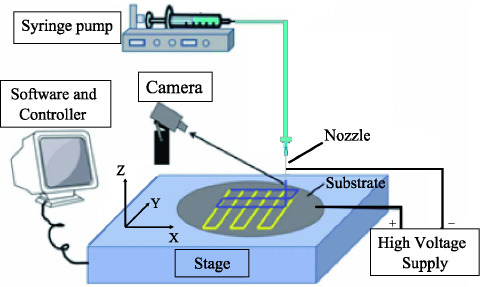
Sketch diagram of EHD-jetting system.
A three-axis precision stage (PRO165LM, Aerotech Company, USA) was used for scaffold fabrication of different geometries. The stage was driven by linear motors, with the X and Y axes having a travel distance of 150 mm with ±3 μm accuracy. The travel distance of Z axes was 50 mm with ±5 μm accuracy. Polished silicon wafers with diameter of 100 mm and thickness of 0.8 mm, were used as the substrate. The precision stage was controlled using Ensemble IDE software running on a desktop PC and connected through a serial USB port, gave the real-time position and velocity information for monitoring and compensation purposes.
2.2 Material Preparation
PCL is a type of biodegradable polyester normally used for fabrication of scaffolds. A solution of PCL is obtained by dissolving the PCL pellets in acetic acid. PCL pellets with an average molecular weight of 90 kDa, were purchased from Scientific Polymer Products Inc., USA. Acetic acid with 99.7% purity was purchased from Aladdin Industrial Corporation, USA. Material preparation involves dissolving the PCL pellets in acetic acid, and sonicating it in an ultrasonic bath at 6 0 °C until it turns into a colourless viscus liquid. Later on, the solution was degassed for few hours until there were no notable air bubbles.
2.3 Scaffold Characterization
Surface morphology of the PCL scaffold was observed using an optical microscope (BX51M, Olympus, Japan) at a magnification of x50 and a scanning electron microscope (JSM-6510, JEOL, Japan) at an accelerating voltage of 15 kV. Fibre diameter was measured both using the optical microscopy images (using MShot Digital Imaging System software) and from the SEM. In this study, the fiber diameter was measured at 4 points on each fiber and an average value was taken.
2.4 Process Parameters
During the printing process, fibres were laid down on the substrate and a mesh was formed by the raster motion, shown as Figure 2A. Fibre characteristics such as fibre diameter and its uniformity, were adjusted by varying several controllable process parameters[22,23]. In this study, six parameters were considered to have major effects on fibre diameter as well as morphology, and they are discussed below:
Figure 2.
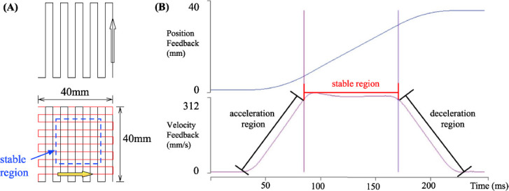
(A) Sketch of raster stage movement pattern; (B) Position feedback and velocity feedback of motorized stage axis (pre-set stage speed=300 mm/s).
(i) Solution Concentration (C): Weight volume ratio of PCL in acetic acid is considered as the solution concentration. During the solvent-based EHD-jetting process, one of the key requirement for fibre collection and 3D structure construction is whether the fibre would solidify over a short distance between the nozzle and the substrate. The concentration solution of 60% to 80% was used in this study.
(ii) Supply voltage (V): When a high voltage is applied between the nozzle and the substrate, charges will be induced within the solution. When a small volume of electrically conductive droplet is exposed to an electric field, the shape of the droplet starts to deform from the shape caused by surface tension alone. When a certain threshold voltage has been reached, the slightly rounded tip inverts and emits a jet of liquid.
(iii) Nozzle-to-substrate distance (D): In a conventional EHD-spinning process, the nozzle to substrate distance ranges from 10 mm to 30 mm[24], which leads to whipping. A smaller distance results in stronger electric field, which causes the solution to overcome the surface tension on the Taylor cone and initiate the EHD-jetting process.
(iv) Stage speed (SS): When the high voltage initiates the Taylor cone, it usually bursts out with an initial velocity of up to 5 m/s[25]. In order to avoid accumulation of solution at the nozzle tip, an appropriate stage speed should be chosen. In this study, the maximum stage speed for scaffold fabrication was set at 0.3 m/s.
(v) Solution feed rate (FR): The syringe pump supplies a constant solution flow, and the feed rate setting can directly affect the fibre formation. It is hard to form a Taylor cone when the feed rate is too low, for it cannot eject enough solution. However, the solution may accumulate at the nozzle tip under a higher feed rate and in turn produce thick fibres.
(vi) Temperature (T): PCL has a glass transition temperature about -60 °C and a low melting point of around 60 °C. Low melting point of the PCL makes it vulnerable during the EHD-jetting process. The temperature mainly influences the viscosity and conductivity of medium, thus changing the surface tension and electrostatic force under the applied electrical force.
2.5 Stage Motion Characterization
Effective fabrication area represents the part of the scaffold, which was fabricated when the actual robotic stage speed approximately equals to the preset stage speed. In this study, a rectilinear raster pattern was used as the standard print pattern as shown in Figure 2A.
Following this pattern, the stage first moves in horizontal zigzag directions. Next it moves in vertical zigzag directions to print a full single layer. Thus, a linear movement can be divided into 3 phases, the acceleration region, stable region, and the deceleration region. As shown in Figure 2B, position feedback displayed that the axis was moved from 0 mm to 40 mm, while the velocity feedback shows the 3-region variation. Then, each fiber began with an acceleration region, then reached the stable region, and finally ended at the deceleration region. Only the fiber fabricated under the stable region can be considered as the effective fabrication area. The stage was built on a servo loop controller, and can be auto-tuned, which involved driving the axis using a predefined input, measuring the resulting data, and calculating a set of servo gains that matched given criteria.
To define the stable region under a varied stage speed and acceleration, a stage tuning test was designed. In order to find the optimal stable region, stage speed was fixed and different stage performance under varied acceleration values and servo gains were compared. Stage performance was obtained from the feedback images. To select the best stage performance, the length of the stable region was compared, and the longest one was chosen as the best. When the stage reached a r elatively stable region, there still existed some fluctuation, and any error below ±5% was defined as sustainable error. Based on these criteria, a set of acceleration values with corresponding stable region length were found and listed in Table 1. In this study, all of the experimental results were based on the scaffold fabricated in the effective fabrication area.
NOMENCLATURE
| C | Concentration (wt%) |
|---|---|
| D | Nozzle to substrate distance (mm) |
| FR | Feed Rate (μL/min) |
| SS | Stage Speed (mm/s) |
| T | Temperature (°C) |
| V | Voltage (kV) |
3. Results and Discussion
3.1 Grid Scaffold Structure and Process Parameters
Effects of two process parameters on fibre diameter were investigated: solution feed rate and motorized stage speed. In addition, the nozzle-to-substrate distance plays an important role in positioning and tuning the degree of solidification. If this distance was below 2.5 mm, the deposited fibres we always straight even at very slow stage speed values. If the nozzle-substrate distance was between 2 mm and 5 mm, straight fibres can only be obtained when the stage speed was larger than that of the jetting speed.
(l)Effects of Solution Feed Rate on Fibre Diameter
Relationship between solution feed rate and fibre diameter has been investigated. Solution feed rate was varied from 1.0 μL/min to 2.0 μL/min at increments of 0.5 μL/min. The other parameters were kept constant: voltage of 3.0 kV, nozzle-to-substrate distance of 3 mm, stage speed of 200 mm/s, and temperature of 20°C. Two concentrations of PCL solution were used: 60% and 70%. For 60% PCL, the measured fibre diameter varied from 18.9 μm to 36.0 μm. For the 70% PCL, the measured fibre diameter varied from 18.7 μm to 37.6 μm. In Figure 3, the variation of the solution feed rate vs the fiber diameter is shown. Solution feed rate at 2.0 μL/min always could generate thicker fibres, and the fibre diameter increases with the solution feed rate. Higher solution feed rate results in increased pressure from the pump acting on the Taylor cone, which leads to an increase in the volume of the solution that comes out of the nozzle. Therefore, higher solution feed rate always causes larger fibre diameter.
Figure 3.
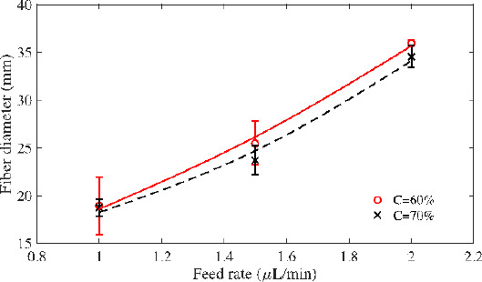
Relationship between feed rate and fibre diameter (V=3 kV, D=3 mm, SS=200 mm/s, and T=20°C).
In this experiment, solution concentration did not have significant influence on the fibre diameter. Both 60% PCL and 70% PCL exhibited similar trends. However, there are other factors that were influenced by varying solution concentration, such as electrical conductivity, surface tension, viscosity, and solvent evaporation rate. All of these factors determine the amount of solution being stretched out from the nozzle tip under high voltage, thus affecting fibre formation. During the process initiation, the surface tension of the solution should be overcome, and then the EHD jets will be stretched. Less acetic acid means fewer frees ions, and a decrease in electrical conductivity. Thus, less solution volume was pulled out of the nozzle under higher concentration. These multiple factors work together to determine the fibre diameter, and some of them are significantly affected by solution concentration and feed rate.
(2) Effects of Stage Speed on Fibre Diameter
Stage speed has significant influence on the positioning of EHD jetted fibres. When this speed is much lower than the speed of jetting, linear, aligned microstructures were achieved even when the motion stage movement was linear. Air turbulence or buckling of solid fibres disturbs the linear deposition of fibres. When the two speeds are closer, the deposited fibres were linear and aligned straight due to the mechanical drawing force. When the stage speed exceeds the jetting speed, fibre diameter can be tuned by varying the stage speed.
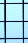
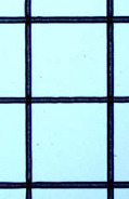
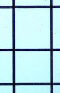
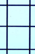
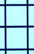
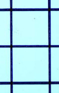
Table 2 shows the relationship between stage speed and fibre diameter. The range of the stage speed used were 100 mm/s to 300 mm/s at increments of 50 mm/s; the supply voltage was 3.0 kV, nozzle-substrate distance was 3.0 mm, and the solution feed rate was 1.5 μL/min. Two different PCL concentrations, 60% and 70%, were used for this experiment.
Table 1.
Stage motion characterization results
| Stage speed (mm/s) | Acceleration region (mm) | Stable region (mm) | Deceleration region (mm) |
|---|---|---|---|
| 50 | 1.7 | 36.3 | 1.9 |
| 100 | 3.6 | 32.8 | 3.6 |
| 150 | 3.6 | 32.4 | 4.0 |
| 200 | 4.3 | 31.2 | 4.5 |
| 250 | 6.1 | 27.6 | 6.3 |
| 300 | 9.1 | 21.2 | 9.7 |
As shown in Figure 4, fibre diameter decreases with increased stage speed. Faster stage speed can effectively reduce the volume of dispensed solution on the substrate, and hence, by increasing the stage speed, thinner fibres can be fabricated. For 70% PCL solution, when the stage speed was 100 mm/s, the average fibre diameter was around 32.8 μm, and when the stage speed was increased to 300 mm/s, the average fibre diameter decreased to 19.3 μm.
Figure 4.
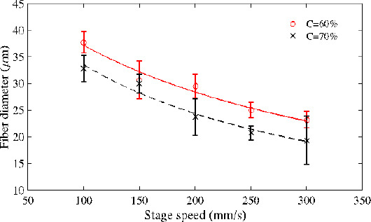
Relationship between feed rate and fibre diameter (FR=1.5 μL/min, D=3 mm, V=3 kV and T=20°C).
3.2 Coiled Structure and Influencing Factors
Coiled structure has more surface area than the normal mesh structure and hence provides more area for the cells to attach and grow. It is also expected to provide better pore interconnectivity and hence increased cell-cell interaction. Coiled structure scaffold is based on the control of the unstable bulking/whipping behaviour observed during EHD-jetting process, in which the unstable jet fiber can be positioned on the substrate by the combined control of process parameters. This section discusses the effects of PCL properties, stage speed, solution feed rate, and solution concentration on the formation of a coiled structure.
(1) Effects of PCL chemical property on EHD-jetting Process
In EHD-jetting process, the pendent drop of polymer solution under electric field is influenced by many forces: columbic, electric, viscoelastic, surface tension, air drag and gravitational force. Among them, electric, viscoelastic and surface tension are the three main forces working on the EHD jetting process, and the last two forces are closely relevant to the viscosity of solution.
PCL shows high solubility in many polar solvents, such as tetrahydrofuran and acetic acid[26]. As a hydrophobic, semi-crystalline polymer, the crystallinity of PCL tends to decrease with increasing molecular weight (MW). The good solubility of PCL, its low melting point (59-64 °C) and exceptional blend-compatibility has stimulated extensive research into its potential application in the biomedical field. The solubility of PCL is strongly dependent on the MW of polymer. Hence, the viscosity of the polymer solution is proportional to the MW of PCL, for the same concentration of solution. As the PCL has a low melting point, the viscosity of the polymer solution decreases rapidly with the increase of temperature, thus lowering the viscoelastic force acting on the Taylor cone during EHD-jetting. Moreover, during the printing process, the polymer chain tends to orient along forced direction and solidifies on substrate upon evaporation of the solvent in which the temperature and humidity show significant influence on the solvent evaporation rate[29-30]. Therefore, the temperature variation directly affects the EHD jetting process and the morphology of the scaffold.
(2) Effects of Process Parameters on the Layout of Scaffold
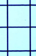
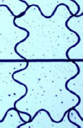
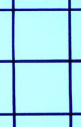
In this experiment, process parameters were C=60% and 70%, FR=1 μL/min, D=3 mm, V=3 kV, and T=25°C. A transition from coils to waves and finally to straight fibres was observed, with the variation of the stage speed, as shown in Table 3. Two critical speeds were observed to aid in this transition between two shapes: straight, and coiled/waved structures, namely 100 mm/s and 250 mm/s, when C=60%.
Table 2.
Optical microscope images of scaffold pattern under varied stage speed (FR=1.5 μL/min, D=3 mm, V=3 kV, and T=20 °C). Scale bar 400 μm___
| Stage speed (mm/s) | ||||||
|---|---|---|---|---|---|---|
| 100 | 150 | 200 | 250 | 300 | ||
| 60% PCL | Scaffold pattern | 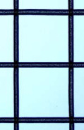 |
 |
 |
 |
 |
| Fiber diameter (μm) | 37.8 | 30.7 | 29.5 | 25.0 | 23.2 | |
| 70% PCL | Scaffold pattern | 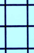 |
 |
 |
 |
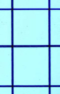 |
| Fiber diameter (μm) | 32.8 | 30.0 | 23.7 | 20.7 | 19.3 | |
When the stage speed was relatively slow, the electrical force, pressure from the pump, and the other forces take charge of the formation of the fibres. Since the stage moves very slowly, there is enough time for the fibres to fold and form coiled/wave structures. However, when the speed increases, the mechanical drawing force of the stage play a main role, and the fibres align in a straight line. With the increase of the stage speed, the fibre diameter becomes thinner and thinner. At a certain point, when the fibre diameter is too thin, the mechanical drawing force generated by the robotic stage will lose control due to the small fibre diameter and the fibres become coiled or wave-shaped again. Splaying might also play a role in the formation of coiled / wave structure but further research is required to study how significant the effect is. This explains the two critical transition speeds of 100 mm/s and 250 mm/s. At C=70%, the lower bound of the transition speed holds good at 100 mm/s while straight to coiled/wave structure transition is not seen at 250 mm/s. As mentioned above in the case for C=60%, at lower stage speed, there is enough time for the fibres to fold and form coiled/wave structures. But at higher speeds (>250 mm/s), while C=60% is easy to trigger the coiled/wave structure, C=70% yields fibres that are not thinner enough to form the coiled/wave structure due to the higher solution concentration. Hence, there is no transition from straight to coiled/wave structure is seen.
(3) Effects of Stage Speed on the Coiled Scaffold
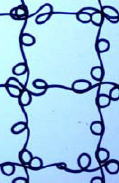
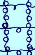
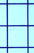
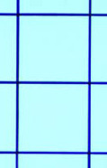
To investigate the influence of stage speed on the coiled scaffold pattern, the process parameters were set as following: nozzle-to-substrate distance of 3 mm, solution concentration of 60%, solution feed rate of 1.5 μL/min, ambient temperature of 25 °C, and the stage speed was varied from 100 mm/s to 250 mm/s at increments of 50 mm/s. Table 4 shows the optical microscope images of fabricated single layer scaffolds.
Table 3.
Optical microscope images of single layer scaffold under varied stage speed (FR=1 μL/min, D=3 mm, V=3 kV, T=25 °C). Scale bar 400 μm_______
| Stage speed (mm/s) | ||||||
|---|---|---|---|---|---|---|
| 50 | 100 | 150 | 200 | 250 | 300 | |
| 60%PCL | 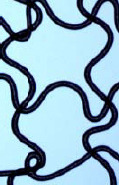 |
 |
 |
 |
 |
 |
| 70%PCL | 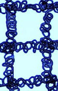 |
 |
 |
 |
 |
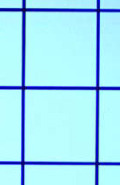 |
Table 4.
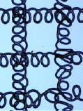
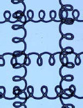
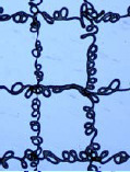
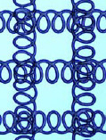
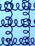
Optical microscope images of single layer scaffold under varied stage speed and solution feed rate (C=60%, D=3 mm, V=3 kV, T=25 °C). Scale bar 400 μm________
| Feed rate | Stage speed (mm/s) | |||
|---|---|---|---|---|
| 100 | 150 | 200 | 250 | |
| 1.5μL/min | 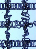 |
 |
 |
 |
| 2.0μL/min | 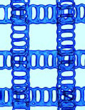 |
 |
 |
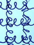 |
In this experiment, the temperature was 25 °C, which is 5 °C higher than the previous single layer grid structure fabrication (Table 2). With the increase of temperature, the solution viscosity decreased, aiding the traveling liquid jet stream to flow easily, being subject to a variety of forces. And then, the EHD jetting process undergoes an instable phase, which directly results in the formation of the coiled structure scaffold. The stage speed plays a s econdary role in this experiment by just guiding the scaffold pattern. Therefore, all the scaffold patterns are coiled and the stage speed variation resulted in slight differences in the coiled structure morphology. During the EHDjetting process, the liquid jet stream exiting from the nozzle is subjected to a variety of forces with different effects. If the forces are unbalanced, instability of the jet occurs. The increased surface tension at the Taylor cone and the electrical force causes the whole EHDjetting process to be unstable during this period and forms coiled structures. However, by tuning the parameters, consistent coiled patterns were obtained. For instance, at a stage speed of 100 mm/s, the coiled structure was more uniform when the feed rate was increased from 1.5 to 2 μL/min.
From Table 4, when the stage speed is low, there were more coiled loops in a single fibre. Apart from this, the low stage also resulted in thicker fibre diameter. Comparing the fibres printed at a stage speed of 100 mm/s with that of 150 mm/s, the fibre diameter is smaller and the loop diameter is larger. Both the low stage speed and high stage speed have less likelihood to fabricate a uniform coiled pattern. For both the concentration values of 60% and 70%, the coils were unstable and non-uniform at the extreme ends of stage speed, namely at 100 mm/s and 250 mm/s.
As shown in Table 4, an increasing stage speed from 100 mm/s to 250 mm/s results in stretching of the EHD-jetted fibres to form loose spiral structure scaffold. The structural uniformity linearly decreases with stage speed. Under a smaller stage speed, the fibre was mainly stretched by electrical field, and the mechanical drawing force only plays a guiding role in positioning the fibres along the motion direction. The shape of deposited structure is determined by the relative velocity and the instability of jetting, while the other processing parameters are kept constant. As the stage speed was increased to 250 mm/s, the mechanical drawing force becomes an important influencer in drawing the fibres, thus resulting in loose spiral structures rather than the uniform coiled structure.
3.3 Multilayer Scaffold Fabrication
From the insights gained by the experiments done in the previous sections on single layer scaffolds of grid and coiled structure, multi-layer scaffolds were fabricated using PCL material. SEM images show the surface topography, morphology features of the multi-layer scaffolds (Figure 5). The process parameters of this grid structure scaffold were C=60%, V=3 kV, D=3 mm, FR=2 μL/min, SS=250 mm/s, and T=25 °C, as shown in Figure 5A. In this structure, the average fibre diameter and pore size were 15 μm and 400 μm respectively. The fibers are precisely oriented. Figure 5B and 5C shows the front and rear view of the multilayer coiled structure scaffold. The process parameters used in fabricating the multi-layer structure were C= 60%, V=3 kV, D=3 mm, FR=2 |L/min, SS= 250 mm/s, and T=25 °C.
Figure 5.
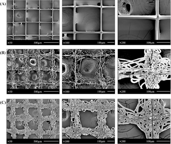
SEM images for fabricated multi-layer scaffolds: (A) gird structure scaffold; process parameters are C=70%, V=3 kV, D=3 mm, FR=2 |L/min, SS=250 mm/s, T=25 °C; (B) front view of coiled structure scaffold; process parameters are C=60%, V=3 kV, D=3 mm, FR=2 |L/min, SS=250 mm/s, T=25 °C; (C) rear view of the coiled structure scaffold.
A proper scaffolds’ physical property is one of the most important prerequisites for tissue engineering applications, which include thickness, porosity, strength, and the ability for the cells to attach and grow. Porosity(Π) is defined as the percentage of void space in a s olid, and it is a morphological property independent of the material[27]. It is calculated by using Equation (1)
Π =1− ρ scaffold / ρ0 (1)
where pscaffold is the density of the EHD-jetting fabricated scaffold and p0 is the bulk density of the PCL. Porosity of biomimetic scaffolds plays a critical role in tissue formation both in vitro and in vivo. Comparing Figure 5A and 5B, it is easy to conclude that void space of coiled structure scaffold is much smaller than the grid structure scaffold, which means the porosity of coiled structure is smaller than the gird structure. However, the surface area of coiled structure is higher than the grid structure, thus increasing the cell attachment area, which might benefit the cellular growth. In the coiled structure scaffolds, the small holes with different sizes might afford the diversity of cell attachment.
While the grid structure was obtained at a concentration of 70%, coiled structure was obtained at a concentration of 60%, keeping all the other parameters the same. In this experiment, the stability of the jet decreased with the solution concentration, which directly results in the formation of coiled structure. Besides, the printing temperature may also trigger the formation of coiled structure. Moreover, comparing the front view and the rear view of the coiled scaffolds, the first layer was flattened, and the reasons might be insufficient time for solidification due to the low concentration (60%), and thinner fibre diameter.
It is worth mentioning that the fabrication of coiled and wave structure scaffolds, both single layer and multi-layer, using the process parameters given, possessed both repeatability and reproducibility. At least 15 scaffolds were fabricated for each combination of process parameters and used for SEM measurement and cell culture study. The SEM results show that around 80% of the samples show very similar microstructure patterns under the same fabrication condition combination.
4. Conclusion
EHD-jetting technique can be used to direct-write high-viscosity solution into continuous high-resolution fibres. Thus, EHD-jetting could be used for fabrication of multi-layer scaffolds with various morphology and resolution that could be achieved by tuning key process parameters: the stage speed, the solution concentration, the nozzle-to-substrate distance, the temperature, and the applied voltage. The mechanical drawing force controlled by the stage speed plays a critical role in the determination of resolution, positioning, and alignment of the fibres. Arrayed diverse structures like the coiled scaffolds can potentially be applied in soft tissue repair and 3D cell culture in regenerative medicine. Cell attachment and proliferation has to be investigated in the future by further cell culture studies on these multi-layer coiled scaffolds.
Conflict of Interest and Funding
No conflict of interest was reported by the authors. This research is supported by the Jiangsu Province Science and Technology Support Programme, China under Grant No BE2013057 and Suzhou Science and Technology Program under Grant No. SYG201418.
References
- 1.Yeong W Y, Chua C K, Leong K F, et al. Rapid prototyping in tissue engineering:challenges and potential. Trends in Biotechnology. 2004;22(12):643–652. doi: 10.1016/j.tibtech.2004.10.004. http://dx.doi.org/10.1016/j.tibtech.2004.10.004. [DOI] [PubMed] [Google Scholar]
- 2.Wang X, Drew C, Lee S H, et al. Electrospun nanofibrous membranes for highly sensitive optical sensors. NanoLetters. 2002;2(11):1273–1275. http://dx.doi.org/10.1021/nl020216u. [Google Scholar]
- 3.Li W J, Laurencin C T, Caterson E J, et al. Electrospun nanofibrous structure:a novel scaffold for tissue engineering. Journal of Biomedical Materials Research. 2002;60(4):613–621. doi: 10.1002/jbm.10167. http://dx.doi.org/10.1002/jbm.10167. [DOI] [PubMed] [Google Scholar]
- 4.Min B M, Lee G, Kim S H, et al. Electrospinning of silk fibroin nanofibers and its effect on t he adhesion and spreading of normal human keratinocytes and fibroblasts in vitro. Biomaterials. 2004;25(7):1289–1297. doi: 10.1016/j.biomaterials.2003.08.045. http://dx.doi.org/10.1016Zj.biomaterials.2003.08.045. [DOI] [PubMed] [Google Scholar]
- 5.Megelski S, Stephens J S, Chase D B, et al. Micro and nanostructured surface morphology on e lectrospun polymer fibers. Macromolecules. 2002;35(22):8456–8466. http://dx.doi.org/10.1021/ma02044a. [Google Scholar]
- 6.Jin H J, Fridrikh S V, Rutledge G C, et al. Electrospinning bombyx mori silk with poly (ethylene oxide) Biomacromolecules. 2002;3(6):1233–1239. doi: 10.1021/bm025581u. http://dx.doi.org/10.1021/bm025581u. [DOI] [PubMed] [Google Scholar]
- 7.Vijayavenkataraman S, Lu W F, Fuh J Y H. 3D bioprinting of skin:A state-of-the-art review on modelling, materials, and processes. Biofabrication. 2016;8(3):p032001. doi: 10.1088/1758-5090/8/3/032001. http://dx.doi.org/10.1088/1758-5090/8/3/032001. [DOI] [PubMed] [Google Scholar]
- 8.Chizhik S A, Wierzcholski K, Trushko A V, et al. Properties of cartilage on micro- and nanolevel. Advances in Tribology. 2011;2010 http://dx.doi.org/10.1155/2010/243150. [Google Scholar]
- 9.Teo W E, Ramakrishna S. A review on electro-spinning design and nanofibre assemblies. Nanotechnology. 2006;17(14):R89. doi: 10.1088/0957-4484/17/14/R01. http://dx.doi.org/10.1088/0957-4484/17/14/R01. [DOI] [PubMed] [Google Scholar]
- 10.Theron A, Zussman E, Yarin A. Electro-static field-assisted alignment of electrospun nanofibers. Nanotechnology. 2001;12(3):384. http://dx.doi.org/10.1088/0957-4484/12/3/329. [Google Scholar]
- 11.Bhattarai N, Edmondson D, Veiseh O, et al. Electrospun chitosan-based nanofibers and their cellular compatibility. Biomaterials. 2005;26(31):6176–6184. doi: 10.1016/j.biomaterials.2005.03.027. http://dx.doi.org/10.1016/j.biomaterials.2005.03.027. [DOI] [PubMed] [Google Scholar]
- 12.Teo W E, Kotaki M, Mo X, et al. Porous tubular structures with controlled fibre orientation using a modified electrospinning method. Nanotechnology. 2005;16(6):918. http://dx.doi.org/10.1088/0957-4484/16/6/049. [Google Scholar]
- 13.Baker B M, Mauck R L. The effect of nanofiber alignment on the maturation of engineered meniscus constructs. Biomaterials. 2007;28(11):1967–1977. doi: 10.1016/j.biomaterials.2007.01.004. http://dx.doi.org/10.1016/j.biomaterials,2007.01.004. [DOI] [PMC free article] [PubMed] [Google Scholar]
- 14.Sun D, Chang C, Li S, et al. Near-field electrospinning. Nano Letters. 2006;6(4):839–842. doi: 10.1021/nl0602701. http://dx.doi.org/10.1021/nl0602701. [DOI] [PubMed] [Google Scholar]
- 15.Sun D, Lin L, Wu D, et al. Electrospun ordered nanofibers on Si and SiO2substrate. In 2nd IEEE International Conference on Nano/Micro Engineered and Molecular Systems, NEMS'07, IEEE. 2007:72–76. [Google Scholar]
- 16.Chang C, Limkrailassiri K, Lin L. Continuous near-field electrospinning for large area deposition of orderly nanofiber patterns. Applied Physics Letters. 2008;93(12):123111. http://dx.doi.org/10.1063/L2975834. [Google Scholar]
- 17.Padmanabhan T, Kamaraj V, Magwood L, et al. Experimental investigation on the operating variables of a near-field electrospinning process via response surface methodology. Journal of Manufacturing Processes. 2011;13(2):104–112. http://dx.doi.org/10.1016/j .jmapro.2011.01.003. [Google Scholar]
- 18.Wei C, Dong J. Direct fabrication of high-resolution three-dimensional polymeric scaffolds using electrohydrodynamic hot jet plotting. Journal of Micromechanics and Microengineering. 2013;23(2):025017. http://dx.doi.org/10.1088/0960-1317/23/2Z025017. [Google Scholar]
- 19.Park J U, Hardy M, Kang S J, et al. High-resolution electrohydrodynamic jet printing. Nature Materials. 2007;6(10):782–789. doi: 10.1038/nmat1974. http://dx.doi.org/10.1038/nmat1974. [DOI] [PubMed] [Google Scholar]
- 20.Kim B H, Onses M S, Lim J B, et al. High-resolution patterns of quantum dots formed by electrohydrodynamic jet printing for light-emitting diodes. Nano Letters. 2015;15(2):969–973. doi: 10.1021/nl503779e. http://dx.doi.org/10.1021/nl503779e. [DOI] [PubMed] [Google Scholar]
- 21.Lee H, Seong B, Kim J, Jang Y, et al. Direct alignment and patterning of s ilver nanowires by electro-hydrodynamic jet printing. Small. 2014;10(19):3918–3922. doi: 10.1002/smll.201400936. http://dx.doi.org/10.1002/smll.201400936. [DOI] [PubMed] [Google Scholar]
- 22.Croisier F, Duwez A S, Jerome C, et al. Mechanical testing of electrospun PCL fibers. Acta Biomaterialia. 2012;8(1):218–224. doi: 10.1016/j.actbio.2011.08.015. http://dx.doi.org/10.1016/j. actbio.2011.08.015. [DOI] [PubMed] [Google Scholar]
- 23.Wang H, Vijayavenkataraman S, Wu Y, et al. Investigation of process parameters of electrohydro-dynamic jetting for 3D printed PCL fibrous scaffolds with complex geometries. International Journal of Bioprinting. 2016;2(1):63–71. http://dx.doi.org/10.18063/IJB.2016.01.005. [Google Scholar]
- 24.Kowalewski T, Blonski S, Barral S. Experiments and modelling of e lectrospinning process. Technical Sciences. 2005;53(4) [Google Scholar]
- 25.Koombhongse S, Liu W, Reneker D H. Flat polymer ribbons and other shapes by electrospinning. Journal of Polymer Science Part B:Polymer Physics. 2001;39(21):2598–2606. http://dx.doi.org/10.1002/polb.10015. [Google Scholar]
- 26.Woodruff M A, Hutmacher D W. The return of a forgotten polymer —polycaprolactone in the 21st century. Progress in Polymer Science. 2010;35(10):1217–1256. http://dx.doi.org/10.1016/j.progpolymsci.2010.04.002. [Google Scholar]
- 27.Karageorgiou V, Kaplan D. Porosity of 3D biomaterial scaffolds and osteogenesis. Biomaterials. 2005;26(27):5474–5491. doi: 10.1016/j.biomaterials.2005.02.002. http://dx.doi.org/10.1016/j.biomaterials.2005.02.002. [DOI] [PubMed] [Google Scholar]
- 28.Garg K, Bowlin G L. Electrospinning jets and nanofibrous structures. Biomicrofluidics. 2011;5(1):013403. doi: 10.1063/1.3567097. http://dx.doi.org/10.1063/1.3567097. [DOI] [PMC free article] [PubMed] [Google Scholar]
- 29.Lee A, Jin H, Dang H W, et al. Optimization of experimental parameters to determine the jetting regimes in electrohydrodynamic printing. Langmuir. 2013;29(44):13630–13639. doi: 10.1021/la403111m. http://dx.doi.org/10.1021/la403111m. [DOI] [PubMed] [Google Scholar]
- 30.Pillay V, Dott C, Choonara Y E, et al. A review of the effect of pr ocessing variables on the fabrication of electrospun nanofibers for drug delivery applications. Journal of Nanomaterials. 2013;13(1):789289. http://dx.doi.org/10.1155/2013/789289. [Google Scholar]


