

Abstract
Multilayers of [Co/Ni(t)/Co/Pt]×8 with varying Ni thickness were investigated for possible use as a free layer in magnetic tunnel junctions and spintronics devices. The thickness t of the Ni sub-layer was varied from 0.3 nm to 0.9 nm and the resulting magnetic properties were compared with (Co/Ni) and (Co/Pt) multilayers. As determined from magnetic force microscopy, magnetometry and ferromagnetic resonance measurements, all multilayers exhibited perpendicular magnetic anisotropy. Compared with (Co/Pt) multilayers, the sample with t of 0.9 nm showed almost the same anisotropy field of μ0Hk = 1.15 T but the damping constant was 40% lower. These characteristics make these multilayers attractive for spin torque based magnetoresistive devices with perpendicular anisotropy.
Keywords: magnetic multilayers, perpendicular magnetic anisotropy, magnetic force microscopy, ferromagnetic resonance
1. Introduction
Intensive studies have been conducted on materials with perpendicular magnetic anisotropy (PMA) for their application in magnetoresistive devices such as magnetic random access memory (MRAM) [1–10], and spin torque oscillators (STO) [11–16]. These materials enable the down-scaling of the devices due to their significantly larger magnetic anisotropy compared with ferromagnets with in-plane anisotropy. It is also known that the current required for magnetization switching in a ferromagnet by spin transfer torque effect is proportional to its damping constant α. Very recently, it has also been demonstrated that these materials can host so-called magnetic droplet solitons, which require both high PMA and low α [17–21]. Moreover, the current required to switch perpendicular anisotropic materials is smaller than that of materials with in-plane magnetization. Among a relatively large choice of PMA materials for spintronics application, (Co/X), (CoFe/X) where X is Pt or Pd, and (Co/Ni) multilayers were widely explored. In fact, their magnetic properties can be easily tailored by adjusting the thickness of each sublayer and the number of repeats. It has been found that (Co/X) and (CoFe/X) multilayers have larger α values compared to (Co/Ni) multilayers [22, 23], but (Co/Ni) multilayers suffer from relatively low PMA. In this paper, the magnetic properties of a combination of (Co/Pt) and (Co/Ni) multilayers were investigated with the aim of improving both the damping constant and magnetic anisotropy. Using magnetometry and ferromagnetic resonance measurements, we show that this new structure has a clear potential to reduce α while maintaining high PMA.
2. Experiments
All samples were deposited on thermally oxidized Si substrates using DC-magnetron sputtering in a chamber with a base pressure below 4 × 10⁻⁶ Pa (3 × 10⁻⁸ Torr) at ambient temperature. The film structure is schematically shown in the inset of figure 1 which consists of Ta(4 nm)/Pt(3 nm)/[Co(0.3)/Ni(t)/Co(0.3)/Pt(0.8)]×8/cap, where the numbers represent the thickness of each layer in nanometers. In this study, the thickness t of the Ni layer was varied from 0.3 nm to 0.9 nm with a step size of 0.2 nm. The thicknesses of all single layers were determined by x-ray reflectometry and the film thicknesses of each layer in the final stacks were estimated from the deposition rate and deposition time. The capping layer was a lamination of 3 nm Pt and 2 nm Ta to protect the whole stack from oxidation.
Figure 1.
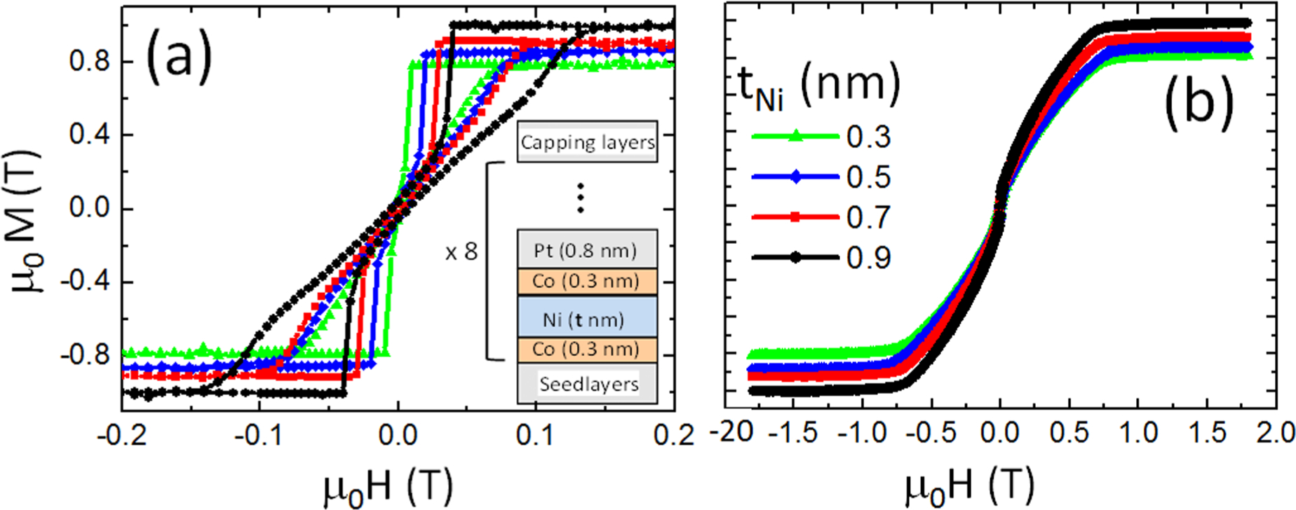
Magnetization versus magnetic field for [Co/Ni(t)/Co/Pt]×8 multilayers with different Ni thicknesses. The magnetic field is applied (a) perpendicular to film plane and (b) along the film plane. Inset is a schematic representation of the multilayer structure where the seed layers are Ta(4 nm)/Pt(3 nm) and capping layers are Pt(3 nm)/Ta(2 nm).
3. Results and discussions
Figure 1 shows the magnetization versus magnetic field for (Co/Ni/Co/Pt) multilayers with different Ni thicknesses in both (a) out-of-plane and (b) in-plane directions. A clear magnetization rotation can be seen when the external magnetic field is applied along the film plane (hard axis). This confirms that these multilayers exhibit perpendicular anisotropy. The nucleation field becomes more positive as Ni thickness increases (figure 1(a)), which may be attributed to an increase in the demagnetizing field. Similar results were reported for (Co/Ni) [23, 24], and (CoFeB/Pd) [25]. The bow-tie shape seen in these multilayers for large number of repeats was accompanied by a formation of magnetic domains to minimize the magnetostatic energy [26]. Magnetic force microscopy (MFM) imaging was conducted on these films in the demagnetized state. Stripe domains were observed in all of them but the size of the domains decreased for samples with thicker Ni in the multilayer stack. These are typical band domains for materials with perpendicular anisotropy. For t = 0.3 nm, stripe domains with less than 500 nm width can be observed (figure 2(a)). As the Ni thickness increases, the domain size shrinks continuously down to about 100 nm for the sample with t = 0.9 nm (figure 2(d)). The saturation magnetization was determined independently for each multilayer from magnetometry measurements as can be seen in figure 1. The measured saturation magnetization μ0MS shows a small dependence on Ni thickness (figure 1(a)) which varies from about 0.82 mT for t = 0.3 nm to about 0.99 mT for t = 0.9 nm. This is understandable from the simple fact that the total thickness of magnetic elements (Co and Ni) in relation to the non-magnetic elements (Pt) in the stack increases.
Figure 2.
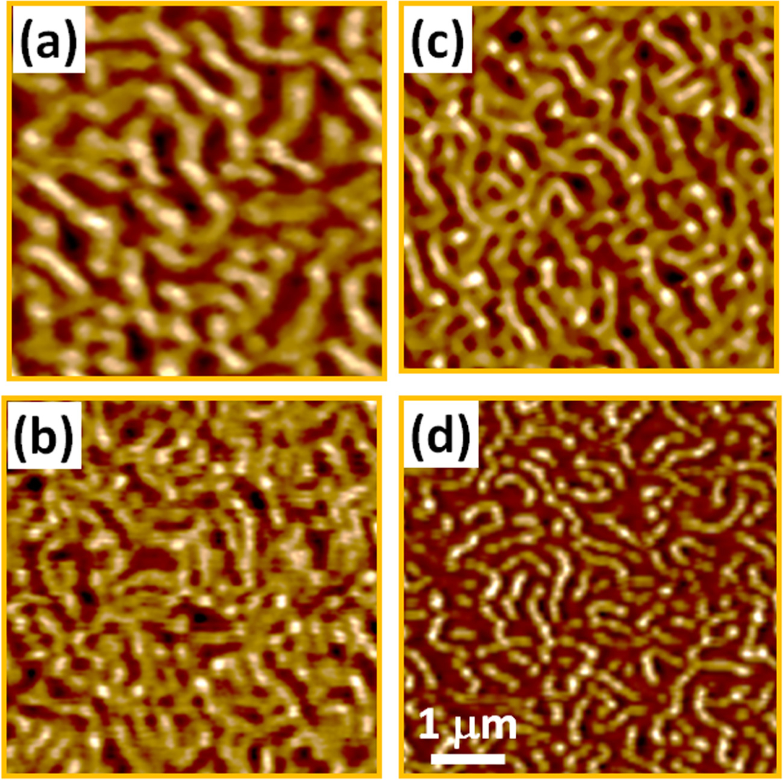
Magnetic force microscopy images for [Co/Ni(t)/Co/Pt]×8 multilayers with (a) t = 0.3 nm, (b) t = 0.5 nm, (c) t = 0.7 nm and (d) t = 0.9 nm. A reduction in domain size can be seen as the Ni thickness increases.
Broadband ferromagnetic resonance (FMR) in perpendicular geometry was used to determine the effective magnetization Meff = MS − Hk, the g-factor, and the damping constant α, where Hk is the magnetic anisotropy field. Samples were placed face-down on a co-planar waveguide while the transmission through the waveguide was measured as a function of the external magnetic field applied perpendicular to the sample surface with a vector-network-analyzer. The resonance field Hres and linewidth ΔH were determined for a given frequency by fitting the resonance to the complex susceptibility as described in [27]. The frequency f versus the resonance field Hres is described by the Kittel equation:
| (1) |
where γ = gμB/ħ is the gyromagnetic ratio, μB is the Bohr magnetron, and ħ is the reduced Planck’s constant. Figure 3(a) shows examples of Hres versus f along with fits to equation (1) used to determine Meff and g.
Figure 3.
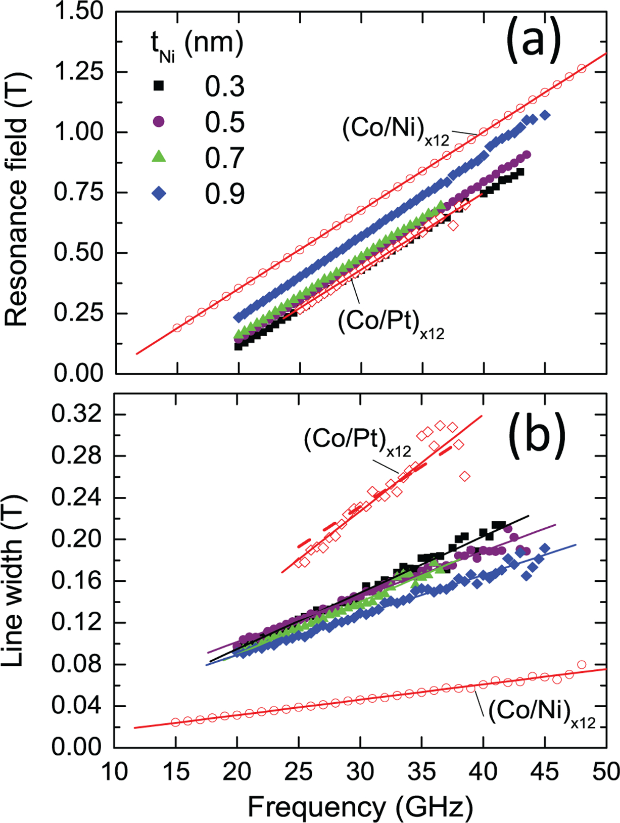
Frequency dependence of (a) resonance field and (b) linewidth for (Co/Ni/Co/Pt) multilayers with different Ni thicknesses. Values for (Co/Pt) and (Co/Ni) multilayers with 12 repeats are included for comparison.
The damping constant α in addition to the inhomogeneous broadening ΔH0 can be obtained from ΔH according to the equation [27–31]:
| (2) |
Negative values of μ0Meff around −0.5 T are obtained for the multilayers with different Ni thicknesses indicating the outof-plane easy axis of the magnetization. These values are larger in magnitude as compared to those of [Co(0.3 nm)/Ni(0.6 nm)]×12 but in the same range as those of [Co(0.3 nm)/Pt(0.8 nm)]×12 (table 1). The g-factor obtained from the slope of resonance field versus frequency is reported in table 1. Values of g-factor between 2.17 and 2.18 were obtained for all multilayers, except for (Co/Pt)×12 which showed slightly higher values (g = 2.2). From the linear fit of ΔH versus f shown in figure 3(b), ΔH0 is obtained. The measured inhomogeneous linewidth contribution is scattered around a value of zero for all the investigated samples with the exception of the (Co/Pt)×12 reference sample. Such values of ΔH0 further validate the high quality of the samples used in this study. However, the negative value of ΔH0 obtained for the (Co/Pt)×12 multilayer (table 1) is unphysical and is speculated to be a result of the increase in scatter of the FMR linewidth data for that sample. As a result, we include a fit to the data in figure 3(b) (dashed red line) where ΔH0 is constrained to be a positive value. This constrained fit has a minimal effect on the value of alpha obtained in this study and we include values of alpha for both fitting approaches in our analysis. It can be concluded from table 1 that the anisotropy strength of (Co/Ni/Co/Pt) is comparable to the (Co/Pt) multilayer as indicated by Meff, but exhibit values of the g-factor and ΔH0 that are more comparable to the (Co/Ni) multilayer. It can be noticed from figure 3, that Hres and ΔH can be well fitted to equations (1) and (2), except for the reference (Co/Pt) multilayer where a decreased signal-to-noise ratio introduced significant scatter to the data above 35 GHz. Figure 4 shows the saturation magnetization, anisotropy field and the damping constant for (Co/Ni/Co/Pt) multilayers as a function of Ni thickness. Values of (Co/Ni) and (Co/Pt) multilayers as references are indicated by the arrows.
Table 1.
Values of the effective magnetization, g-factor and inhomogeneity broadening for different Ni thicknesses in (Co/Ni/Co/Pt) multilayers.
| T (nm) | μ0Meff (T) | g | μ0ΔH0 ± σ (T) |
|---|---|---|---|
| 0.3 | −0.547 | 2.17 | −0.007 ± 0.006 |
| 0.5 | −0.511 | 2.18 | +0.011 ±0.005 |
| 0.7 | −0.499 | 2.17 | −0.006 ± 0.005 |
| 0.9 | −0.424 | 2.18 | +0.009 ± 0.005 |
| (Co/Ni)×12 | −0.303 | 2.18 | 0.002 ± 0.001 |
| (Co/Ni)×12 | −0.539 | 2.21 | −0.06 ± 0.04 |
Note: For comparison the cases of (Co/Ni)×12 and (Co/Pt)×12 are also reported. The values of σ are the uncertainties on the line width.
Figure 4.
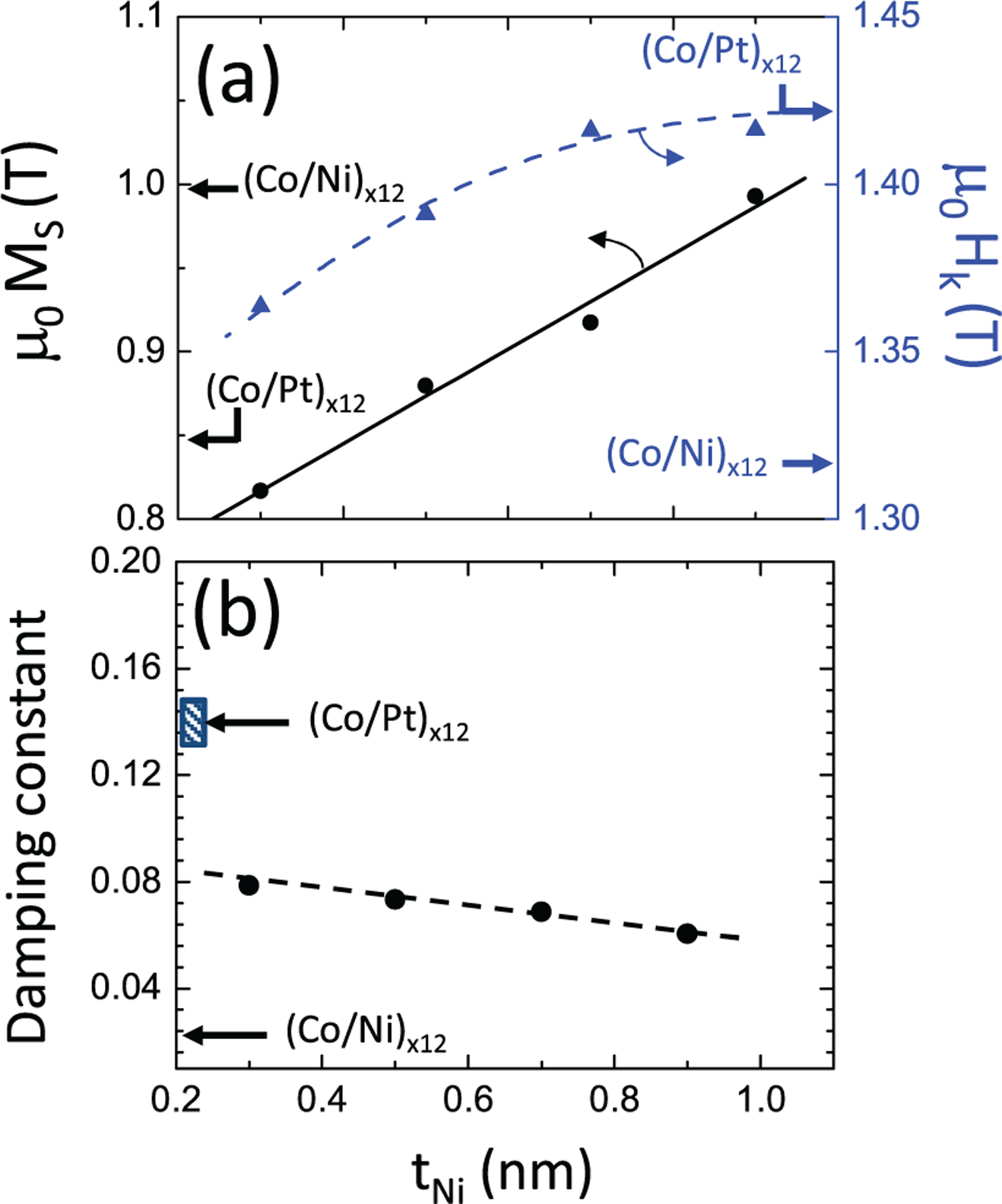
Plots of (a) saturation magnetization and magnetic anisotropy field and (b) damping constant as a function of Ni thickness in (Co/Ni/Co/Pt) multilayer. The black and blue arrows indicate the values of MS, Hk and α for (Co/Pt) and (Co/Ni) multilayers with 12 repeats. The dashed region is the range of damping constant values for (Co/Pt) multilayer using the two fitting lines used in figure 3(b).
To evaluate the magnetic anisotropy field for the samples, MS was measured by magnetometry and by using Meff values reported in table 1, Hk was obtained and plotted in figure 4(a). A clear improvement of Hk with Ni thickness can be seen.
There is a linear dependence of μ0Hk with Ni thickness starting from 1.36 T for t = 0.3 nm Ni to about 1.41 T for t = 0.9 nm. This latter value of μ0Hk is closer to (Co/Pt)×12 with 1.42 T. For comparison, Hk values for (Co/Pt) and (Co/Ni) multilayers are shown in figure 4(a). The second key parameter of interest in this study is the damping constant. From the fit of equations (1) and (2) to the experimental data, α could be obtained and plotted as shown in figure 4(b). For t = 0.3 nm, α of 0.07 was measured for (Co/Ni/Co/Pt) multilayer and decreased monotonically to 0.06 for t = 0.9 nm. This value is between those obtained for (Co/Ni) multilayer (α = 0.02) and (Co/Pt) multilayer (α = 0.15). The dashed region shown in figure 4(b) indicates the values of α for (Co/Pt) using the two linear fits in figure 3(b). From figure 4, it can be seen that it is possible to have both high Hk and low α using (Co/Ni/Co/Pt) multilayer. These materials could be useful for perpendicular magnetic tunnel junction with good stability and low switching current. Still further optimization of (Co/Ni/Co/Pt) is possible by adjusting the thickness of each sub-layer.
4. Conclusion
[Co/Ni(t)/Co/Pt]×8 multilayers with different Ni thickness values were investigated by MFM, magnetometry and FMR measurements. It was found that μ0MS improves with Ni thickness, changing from 0.81 T (MS = 650 emu cm−3) for t = 0.3 nm to 0.99 T (MS = 790 emu cm−3) for t = 0.9 nm. FMR measurements and MFM imaging revealed that these multilayers exhibit an out-of-plane magnetic anisotropy. The anisotropy field for the sample with thicker Ni reached a value of 1.41 T which is comparable to (Co/Pt)×12. For (Co/Ni)×12 multilayers case, the measured μ0Hk was about 1.32 T. Furthermore, the damping constant shows a decrease with Ni thickness and reached a value of 0.06 for t = 0.9 nm which is 2.5 times lower than (Co/Pt). Although this value is still larger than (Co/Ni)×12, a combination of both larger Hk and low α makes these multilayers attractive as a free layer in spin torque based magnetoresistive devices with perpendicular anisotropy.
Acknowledgments
R Sbiaa would like to thank the Sultan Qaboos University for the financial support under Grant number IG/SCI/PHYS/14/09. Support from the Swedish Foundation for Strategic Research (SSF), the Swedish Research Council (VR), and the Knut and Alice Wallenberg foundation (KAW) is gratefully acknowledged.
References
- [1].Mangin S, Ravelosona D, Katine JA, Carey MJ, Terris BD and Fullerton EE 2006. Science 5 210. [DOI] [PubMed] [Google Scholar]
- [2].Law R, Sbiaa R, Liew T and Chong TC 2008. IEEE Trans. Magn 44 2612 [Google Scholar]
- [3].Yakushiji K. et al. Appl. Phys. Lett. 2010;97:c232508. [Google Scholar]
- [4].Ikeda S. et al. Nat. Mater. 2010;9:721. doi: 10.1038/nmat2804. [DOI] [PubMed] [Google Scholar]
- [5].Amiri PK. et al. Appl. Phys. Lett. 2011;98:1125071. [Google Scholar]
- [6].Meng H, Sbiaa R, Lua SYH, Wang CC, Akhtar MAK, Wong SK, Luo P, Carlberg CJP and Ang KSA 2011. J. Phys. D: Appl. Phys 44 405001 [Google Scholar]
- [7].Wang CC, Bin Akhtar MAK, Sbiaa R, Meng H, Sunny LYH, Wong SK, Ping L, Carlberg P and Arthur AKS 2012. Japan. J. Appl. Phys 51 013101 [Google Scholar]
- [8].Gan H. et al. Appl. Phys. Lett. 2014;105:192403. [Google Scholar]
- [9].Fang B, Zhang X, Zhang BS, Zeng ZM and Cai JW 2015. AIP Adv. 5 067116 [Google Scholar]
- [10].Yun SJ, Lim SH and Lee SR 2015. Appl. Phys. Lett 106 132401 [Google Scholar]
- [11].Houssameddine D. et al. Nat. Mater. 2007;6:447. doi: 10.1038/nmat1905. [DOI] [PubMed] [Google Scholar]
- [12].Taniguchi T, Tsunegi S, Kubota H and Imamura H 2014. Appl. Phys. Lett 104 152411 [Google Scholar]
- [13].Tamaru S, Kubota H, Yakushiji K, Yuasa S and Fukushima A 2015. Sci. Rep 5 18134. [DOI] [PMC free article] [PubMed] [Google Scholar]
- [14].Carpentieri M and Lattarulo F 2013. IEEE Trans. Magn 49 3151 [Google Scholar]
- [15].Rippard WH, Deac AM, Pufall MR, Shaw JM, Keller MW, Russek SE and Serpico C 2010. Phys. Rev. B 81 014426 [Google Scholar]
- [16].Mohseni SM, Sani SR, Dumas RK, Persson J, Anh Nguyen TN, Chung S, Pogoryelov Y and Åkerman J 2011. Phys. Status Solidi 5 432 [Google Scholar]
- [17].Mohseni SM. et al. Science. 2013;339:1295. doi: 10.1126/science.1230155. [DOI] [PubMed] [Google Scholar]
- [18].Mohseni SM. et al. Physica B. 2014;435:84. [Google Scholar]
- [19].Chung S. et al. J. Appl. Phys. 2014;115:172612. [Google Scholar]
- [20].Macià F, Backes D and Kent AD 2014. Nat. Nanotechnol 9 992. [DOI] [PubMed] [Google Scholar]
- [21].Lendínez S, Statuto N, Backes D, Kent AD and Macià F 2015. Phys. Rev. B 92 174426 [Google Scholar]
- [22].Pal S, Rana B, Hellwig O, Thomson T and Barman A 2011. Appl. Phys. Lett 98 082501 [Google Scholar]
- [23].Sabino MPR, Tran M, Sim CH, Feng YJ and Eason K 2014. J. Appl. Phys 115 17C51 [Google Scholar]
- [24].Akbulut S, Akbulut A, Özdemir M and Yildiz F 2015. J. Magn. Magn. Mater 390 137 [Google Scholar]
- [25].Sbiaa R, Ranjbar M and Akerman J 2015. J. Appl. Phys 117 17C102 [Google Scholar]
- [26].Sbiaa R, Bilin Z, Ranjbar M, Tan HK, Wong SJ, Piramanayagam SN and Chong TC 2010. J. Appl. Phys 107 103901 [Google Scholar]
- [27].Nembach HT, Silva TJ, Shaw JM, Schneider ML, Carey MJ, Maat S and Childress JR 2011. Phys. Rev. B 84 054424 [Google Scholar]
- [28].Heinrich B, Cochran JF and Hasegawa R 1985. J. Appl. Phys 57 3690 [Google Scholar]
- [29].Farle M. Rep. Prog. Phys. 1998;61:755. [Google Scholar]
- [30].McMichael RD, Twisselmann DJ and Kunz A 2003. Phys. Rev. Lett 90 227601. [DOI] [PubMed] [Google Scholar]
- [31].Shaw JM, Nembach HT and Silva TJ 2014. Appl. Phys. Lett 105 062406 [Google Scholar]