Abstract
Polyetheretherketone (PEEK) constitutes a preferred alternative material for orthopedic implants owing to its good mechanical properties and biocompatibility. However, the poor osseointegration property of PEEK implants has limited their clinical applications. To address this issue, in this study, we investigated the mechanical and biological properties of fully porous PEEK scaffolds with different pore sizes both in vitro and in vivo. PEEK scaffolds with designed pore sizes of 300, 450, and 600 μm and a porosity of 60% were manufactured via fused deposition modeling (FDM) to explore the optimum pore size. Smooth solid PEEK cylinders (PEEK-S) were used as the reference material. The mechanical, cytocompatibility, proliferative, and osteogenic properties of PEEK scaffolds were characterized in comparison to those of PEEK-S. In vivo dynamic contrast-enhanced magnetic resonance imaging, microcomputed tomography, and histological observation were performed after 4 and 12 weeks of implantation to evaluate the microvascular perfusion and bone formation afforded by the various PEEK implants using a New Zealand white rabbit model with distal femoral condyle defects. Results of in vitro testing supported the good biocompatibility of the porous PEEK scaffolds manufactured via FDM. In particular, the PEEK-450 scaffolds were most beneficial for cell adhesion, proliferation, and osteogenic differentiation. Results of in vivo analysis further indicated that PEEK-450 scaffolds exhibited preferential potential for bone ingrowth and vascular perfusion. Together, our findings support that porous PEEK implants designed with a suitable pore size and fabricated via three-dimensional printing constitute promising alternative biomaterials for bone grafting and tissue engineering applications with marked potential for clinical applications.
1. Introduction
Orthopedic implants are widely utilized in clinical practice to repair or reconstruct bone systems damaged by trauma or tumor resection. Nevertheless, potential drawbacks of the most commonly used implant materials, titanium and titanium alloys, include elastic modulus mismatch, stress shielding, and strong interference with standard imaging modalities used to evaluate the repaired bone systems.1−4 As an alternative, polyetheretherketone (PEEK) has gained popularity owing to its comparable elastic modulus to that of human bone, superior mechanical properties, and excellent biocompatibility.5 However, the hydrophobicity and bioinertness of PEEK have limited its clinical application as such poor bioactivity and osteointegration properties led to implant dislocation and eventually result in implant failure.6,7
Numerous attempts have been made to improve the osteointegration of PEEK implants. One common approach is to apply a bioactive coating such as hydroxyapatite, calcium silicate, or bioglass.8−10 However, degradation of the coatings and poor binding force between the coating and implant resulting from the layer of fibrous connective tissue usually lead to osteolysis and implant loosening. Another strategy is to introduce three-dimensional (3D) porous structures during the shape-forming process of bone implant materials, as such structures exhibit an architecture mimicking that of human bone and facilitate cell spreading and differentiation functions. Moreover, the porous structure can provide space for new bone tissue ingrowth and transportation of nutrients, oxygen, and waste.11 Several methods to create surface-porous PEEK scaffolds have been reported. Yuan et al.12 established porous PEEK scaffolds using a chemical method (acid sulfonation treatment and biomimetic mineralization via simulated body fluid incubation), which exhibited better osteointegration and mechanical stability than dense PEEK scaffolds. In turn, Evans et al.13 produced a surface-porous PEEK scaffold via a physical method (melt extrusion and salt-leaching), affording enhanced osteointegration in a rat femoral defect model. However, these traditional techniques cannot precisely control the pore size, porosity, or scaffold interconnectivity. In addition, issues of residual impurities or dead space have also been noted.14 Therefore, the effects of the pore structure on the mechanical and biological properties of porous PEEK scaffolds remain to be clarified.
Recently, additive manufacturing, also known as 3D printing, has been widely used in clinical treatment for bone repair. The 3D-printed materials generated through computer-aided design manufacturing exhibit customized shape along with tailored pore size/porosity and pore interconnectivity to provide the most favorable conditions for cell migration and proliferation to regenerate bone tissue and address patient-specific demands.15,16 However, 3D-printed PEEK scaffolds were rarely reported owing to their properties of high-temperature performance, chemical resistance, and durability.17,18 Recently, the fabrication of PEEK scaffolds using fused deposition modeling (FDM) technology has been described, which provides many advantages such as less material wastage, increased cost-effectiveness, easy operator training, faster implant production, and enhanced patient specificity.19 Specifically, scaffolds prepared using FDM are created by depositing the filament, which often comprises a mixture of PEEK and a binder that is melted and extruded from a hot nozzle, onto the workbench layer-by-layer.20
Previous studies demonstrated that 40–70% porosity is optimal for cell growth and nutrient exchange in bone scaffolds.21 However, the complements of favorable parameters including the pore size, porous structure, and composition of the scaffolds have not yet been investigated. Extensive exploration of the biological performance of porous titanium scaffolds with different pore sizes22,23 has revealed that 200–600 μm pore size presents the highest capacity for cell growth and bone formation.24 Alternatively, smaller pores may inhibit cell proliferation or lead to insufficient vascularization and nutrient transport in vivo, whereas larger pores may decrease scaffold load-bearing capacity and have a greater effect on fatigue lifetime.25,26 Nevertheless, the optimum pore size of PEEK implants for bone ingrowth, particularly 3D-printed implants, remains undefined. A systematic investigation regarding the effects of the pore size of 3D-printed porous PEEK scaffolds on their mechanical and biological properties is, therefore, urgently needed in order to improve the reliability and safety of these scaffolds in clinical applications. Accordingly, in the present study, porous PEEK scaffolds with porosity of 60–70% and defined pore dimensions (300, 450, and 600 μm) were designed and prepared using the FDM approach with the aim of investigating their mechanical and biological properties with respect to bone defect remodeling.
2. Materials and Methods
2.1. Preparation of Porous PEEK Scaffolds by 3D-Printing
A medical-grade PEEK filament with a diameter of 1.75 mm was purchased from Evonik Industries AG (Germany). PEEK scaffolds (Φ = 5 mm, H = 10 mm) with a 3D-porous macrostructure were fabricated layer-by-layer employing FDM. For fabricating porous PEEK scaffolds, 3D models and different pore sizes were designed using CAD modeling software (Mimics; Materialise, Belgium), which was utilized to compile the DICOM data into axial, sagittal, and coronal planes, after which the data were converted into STL files that were used to control the FDM 3D printing machine (Medvance MediPK300, Germany). The PEEK filament used as the 3D-printing ink was supplied to the 3D-printing machine through a feeding tube, then injected into nozzles by melting at 480 °C and deposited layer-by-layer following a specific laydown pattern. Fixative spray was applied to the “cold” print bed for adhesion prior to printing. The 3D structures were printed layer-by-layer (0.1 mm), fusing the layers together. The process was finished within hours. Finally, all the printed scaffolds were subjected to ultrasonic cleaning for 15 min to remove loose pollutants. Porous PEEK scaffolds with average 3D pore sizes of 300, 450, and 600 μm were defined as PEEK-300, PEEK-450, and PEEK-600, respectively. Smooth solid PEEK cylinders (PEEK-S) were also printed using these parameters as controls. Cylinder-shaped samples (Φ5 mm × 10 mm) were used for compression tests and in vivo experiments, whereas disk-shaped samples (Φ5 mm × 2 mm) were used for in vitro assays.
2.2. Characterization of the Scaffolds
Macroscopic morphologies of the different scaffolds were observed using optical microscopy. The microstructures were observed via a scanning electron microscope (JSM-6700F, Japan). Layer thickness and the distance between layers were manually measured using the scanning electron microscopy (SEM) images. The porosity was measured according to the Archimedes method. In brief, the total volume of the scaffolds was marked as V1 and the volume of water in the beaker was marked as V2. Then, the scaffolds were immersed in water for more than 5 min until bubbles no longer emerged. The volume of scaffolds with water-filled pores was marked as V3. The porosity (P) was calculated using following formula 1.
| 1 |
2.3. Mechanical Properties and Water Contact Angle
The mechanical properties of the scaffolds (n = 3 per group) were tested using an all-electric dynamic test instrument (ElectroPuls E1000; INSTRON, Britain). Cylindrical-shaped scaffolds (Φ5 mm × 10 mm) were prepared for compressive strength analysis and tested at 37 °C with a constant displacement rate of 1 mm/min. The compressive stiffness was calculated as described previously.27 For each group, three samples were tested and the load–displacement curves were obtained.
A contact angle goniometer (DSA25; KRUSS, Germany) was used to measure the water contact angle of different PEEK scaffolds. In brief, a liquid droplet was dropped onto the scaffolds vertically using an automatic control syringe, then the shape of the liquid drop was captured by the attached camera and analyzed using the associated software; three samples were measured for each group.
2.4. Isolation and Culture of Human Bone Marrow Mesenchymal Stem Cells
Human bone marrow mesenchymal stem cells (hBMSCs) were obtained from young people who had suffered fractures. All individuals provided signed informed consent. The isolation and identification of hBMSCs were based on our previous studies.28 Cells were then placed in an incubator with 5% carbon dioxide at 37 °C and cultured in basal medium with 10% fetal bovine serum plus 1% antibiotics. Culture passage was conducted when the cell density reached 70 to 80%. Second or third passage cells at 80% confluence were used in the subsequent experiments.
2.5. Morphology of hBMSCs Cultured on Different Scaffolds
To investigate the biocompatibility of PEEK scaffolds, the cytoskeleton and morphology of hBMSCs cultured on the PEEK scaffolds were observed using a confocal laser scanning microscope and a scanning electron microscope. After three days of cell culture, we used a laser scanning confocal microscope (LSM780; ZEISS, Germany) to observe the activity and morphology of the cells using the Live/Dead assay according to the manufacturer’s protocol. In brief, cells were washed twice with phosphate buffered saline (PBS) and then the prepared working fluid was added to the orifice plate. After 30 min of incubation, the excess working fluid was gently aspirated and the cells were washed with PBS prior to observation.
In addition, we further evaluated the morphology of hBMSCs using SEM. First, the cells were fixed with 2.5% paraformaldehyde for 30 min, following which different concentrations of alcohol were utilized for gradient dehydration. Then, the cells were observed before coating with gold.
2.6. Cell Seeding Efficiency and Proliferation
Cell suspension (80,000 cells/100 μL) was added dropwise onto the scaffolds and statically incubated for 1 h at 37 °C to facilitate cell adhesion. Then, the samples were transferred onto a 3D rotator overnight to perform dynamic seeding. The overnight cell-seeding efficiency and proliferation of hBMSCs on the scaffolds were detected using a commercial CCK-8 kit according to our previous study.29 In brief, 5000 cells/well were dropped onto the scaffolds in a 96-well plate and the cell viability was estimated after 7, 14, and 21 days using a spectrophotometer (BioTek, USA) at a wavelength of 450 nm.
2.7. Bone-Related Gene Expression and Alkaline Phosphatase Activity
To evaluate the mRNA transcript levels in the different groups of bone-related genes including those encoding alkaline phosphatase (ALP), runt-related transcription factor-2 (RUNX2), collagen type I (COL-1), and bone morphogenetic protein-2 (BMP-2), total RNA was extracted from hBMSCs using an RNAprep Micro Kit (TaKaRa, Japan) at days 7, 14, and 21. Briefly, the total RNA was extracted using the TRIzol reagent (Invitrogen, USA) and cDNA synthesis was performed using PrimeScript RT Master Mix (TaKaRa). Quantitative real-time polymerase chain reaction (PCR) was performed using the SYBR Green QPCR Master Mix (TaKaRa) with a Light Cycler apparatus (CFX Touch; Bio-rad, USA). Cycling conditions were as follows: reverse transcription at 60 °C for 20 min; activation of HotStarTaq DNA polymerase/inactivation of reverse transcriptase at 95 °C for 1 min; and 40 cycles of 95 °C for 15 s, 60 °C for 15 s, and 72 °C for 45 s. Relative expression level of each target gene was calculated using the 2–ΔΔCt method. The primer sequences for glyceraldehyde 3 phosphate dehydrogenase (GAPDH), ALP, RUNX2, COL1, and OCN are listed in Table 1.
Table 1. Primers Used in Real-Time PCR.
| gene | forward primer sequence (5′–3′) | reverse primer sequence (5′–3′) |
|---|---|---|
| GAPDH | GGAGCGAGATCCCTCCAAAAT | GGCTGTTGTCATACTTCTCATGG |
| ALP | ACCACCACGAGAGTGAACCA | CGTTGTCTGAGTACCAGTCCC |
| RUNX2 | TGGTTACTGTCATGGCGGGTA | TCTCAGATCGTTGAACCTTGCTA |
| COL1 | GAGGGCCAAGACGAAGACATC | CAGATCACGTCATCGCACAAC |
| BMP2 | CAACACCGTGCTCAGCTTCC | TTCCCACTCATTTCTGAAAGTTCC |
For detecting ALP activity, the cells on the porous PEEK were digested and collected at days 7 and 14. Then, the ALP activity levels were evaluated using an ALP Activity Colorimetric Assay Kit (BioVision, USA) and normalized by the total protein content as determined using a MicroBCA protein assay kit (Thermo Scientific Pierce, USA). Furthermore, the ALP levels were also assessed by the BCIP/NBT color reaction using a BCIP/NBT ALP color development kit (Beyotime, China). The collected cells from porous PEEK at day 14 were planted on cell slides. After 48 h, the BCIP/NBT color reaction was performed according to the manufacturerʼs instructions.
2.8. Animal Experiments and Evaluation of Microvascular Perfusion Function by Dynamic Contrast-Enhanced Magnetic Resonance Imaging
All animal surgical procedures were approved by the Animal Experimentation Committee of Huazhong University of Science and Technology. A total of 12 New Zealand white rabbits (male, 2.5–3 kg, 6–7 months old) were used to detect bone regeneration ability. Prior to surgery, the rabbits were anesthetized with ketamine (35 mg/kg) and xylazine (5 mg/kg). Two defects (Φ = 5 mm, H = 10 mm) were created using a drill on critical-sized femoral defect in each rabbit and the different scaffolds were implanted into these defects; samples comprising the solid PEEK scaffolds were considered as the control. Antibiotics were administered continuously for the first three days after surgery to prevent bacterial infection in the wound.
At 4 and 12 weeks after surgical implantation, each anesthetized rabbit was placed in the prone position with limbs fixed using medical elastic bandages. Prior to dynamic contrast-enhanced magnetic resonance imaging (DCE-MRI) (7T MAGNETOM Trio, Siemens, Germany), a T1-weighted sequence (TR = 425 ms; TE = 13 ms; and section thickness = 3 mm) was employed to define the region of interest (ROI). After 30 baseline imagines were acquired, the contrast agent gadopentetate dimeglum (0.8 mmol/kg, MedChemExpress, USA) was injected into the ear vein of the rabbits following which 5 mL saline was administered to flush the ear vein. A total of 500 images were acquired. The maximum enhancement (ME) was defined as the maximum percentage increase (SImax – SIbase) in signal intensity (SI) from the baseline.15,30
2.9. Bone Regeneration Ability of Different Scaffolds In vivo
The rabbits were sacrificed at 4 and 12 weeks after surgery via air embolism. Microcomputed tomography (CT) (Bruker, Belgium) was performed to investigate the bone regeneration of different scaffolds. In brief, the bone samples were scanned using the parameters of 100 kV and 100 μA power and 9 μm per pixel. CT Vol Realistic 3D Visualization software was used for reconstruction of the 3D images and analysis of new bone. CTAn analysis software was used to calculate the bone volume/tissue volume ratio (BV/TV). Subsequently, the fixed implants were embedded in paraffin and 6 mm sections were placed on a slide and stained with hematoxylin & eosin (H&E).
2.10. Statistical Analysis
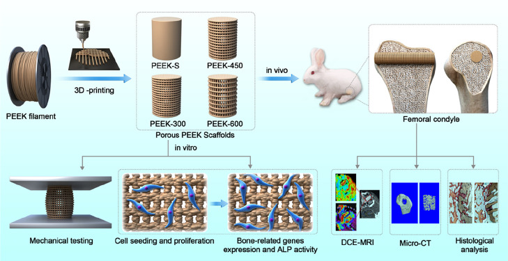
All analysis results are expressed as the means ± standard deviation and generated using GraphPad Prism 7 software (La Jolla, USA). Differences between group means were evaluated using the Studentʼs t-test and one-way analysis of variance (ANOVA) followed by Tukey post hoc tests. P-values <0.05 and <0.01 were considered statistically significant. All experiments were carried out in triplicate (Figure 1).
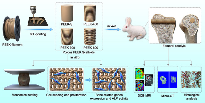
Figure 1.
Schematic illustration of the fabrication of porous PEEK scaffolds and their bioapplication.
3. Results
3.1. Porous PEEK Scaffold Fabrication and Characterization
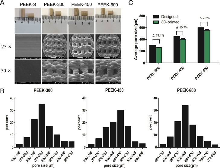
Macroscopic analysis revealed that cylindrical PEEK scaffolds with Φ = 5 mm and H = 10 mm were successfully fabricated using FDM technology (Figure 2A). The SEM images showed that the pore morphology could be reliably controlled without impurities or cracks and that the interconnecting pores were distributed throughout the porous scaffolds (Figure 2A). Pore size distribution analyzed using Mimics 14.11 indicated that over 80% pores were in the range of 200–350, 300–550, and 500–700 μm, respectively, for PEEK-300, PEEK-450, and PEEK-600 (Figure 2B). Porous PEEK samples presented square pore shapes consistent with the designed patterns albeit accompanied by the decreased pore sizes. Specifically, the average 3D pore size of the three porous PEEK scaffold groups was smaller than the design specifications (Figure 2C), with actual pore sizes of 260 ± 26, 401 ± 24, and 556 ± 33 μm, respectively, for PEEK-300, PEEK-450, and PEEK-600 samples. The difference between the average 3D-printed and designed values decreased from 13.1 to 7.3% with the increase of the pore size (Figure 2C).
Figure 2.
Morphological characterization of porous PEEK scaffolds. (A) Macrographs and SEM images of the 3D-printed porous PEEK samples. (B) The actual pore size distribution as analyzed by MIMICS 14.11. (C) Average pore sizes of 3D-printed porous PEEK scaffolds; Δ represents the deviation of the average actual 3D-printed values from those of the designed values.
3.2. Water Contact Angle and Mechanical Properties
The static sessile drop method was used to evaluate the wettability of the samples. The average water contact angles of PEEK-450 and PEEK-600 were smaller than those of PEEK-S and PEEK-300, which had nonwettable surfaces with water contact angles >90° (Figure 3A). With the increase in the pore size, the hydrophilicity of PEEK-450 and PEEK-600 became stronger than that of PEEK-S and PEEK-300. No significant difference was observed in the water contact angle between PEEK-S and PEEK-300 (Figure 3B).
Figure 3.
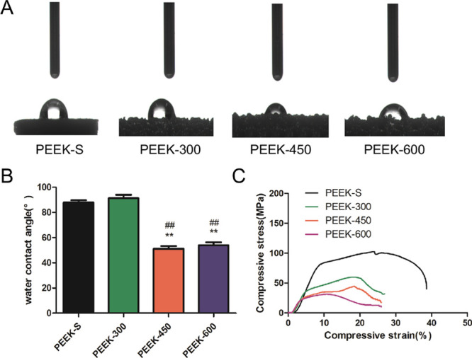
Water contact angle and static mechanical properties of the porous PEEK scaffolds. (A) Water contact angle measurement. (B) Average water contact angle analysis. (C) Static mechanical properties of PEEK scaffolds: stress–strain curves for samples with varying pore sizes. Water contact angle was assessed and evaluated by one-way analysis of variance and Tukey’s post hoc tests. *P < 0.05 and **P < 0.01 compared with PEEK-S; #P < 0.05 and ##P < 0.01 compared with PEEK-300. For each group, n = 3.
Compression test results showed that the features of stress–strain curves were analogous among the different samples. However, the compressive Youngʼs modulus and compressive strength of the samples decreased with the increase in the pore size (Figure 3C). The compressive strength for PEEK-S, PEEK-300, PEEK-450, and PEEK-600 was 102.7 ± 7.5, 59.9 ± 8.3, 44.6 ± 6.4, and 31.2 ± 4.4 MPa, respectively, being lower than the related value of natural bone (130–180 MPa). The elastic modulus for the three groups of porous PEEK scaffolds was 1006.5 ± 84.4, 367.8 ± 63.2, 260.8 ± 45.1, and 231.1 ± 28.2 MPa, respectively (Table 2). The results indicated that the porous PEEK scaffolds were able to withstand partial strength, allowing them to alleviate the stress shielding effect under physiological loading.
Table 2. Quantitation of the Morphological and Mechanical Properties of the PEEK Scaffolds as Determined by Micro-CT Imaging, Sessile Drop Method, Optical Proflometry, and Static Compression Testing.
| PEEK-S | PEEK-300 | PEEK-450 | PEEK-600 | ||
|---|---|---|---|---|---|
| designed | pore size (μm) | 300 | 450 | 600 | |
| porosity (%) | 70 | 70 | 70 | ||
| actual | pore size (μm) | 260 ± 26 | 401 ± 24 | 556 ± 33 | |
| porosity (%) | 59.3 ± 2.5 | 61.5 ± 3.2 | 62.3 ± 2.4 | ||
| interconnectivity (%) | 97.6 ± 0.15 | 98.4 ± 0.12 | 98.6 ± 0.24 | ||
| Young’s modules (MPa) | 1006.5 ± 84.4 | 367.8 ± 63.2 | 260.8 ± 45.1 | 231.1 ± 28.2 | |
| compressive strength (MPa) | 102.7 ± 7.5 | 59.9 ± 8.3 | 44.6 ± 6.4 | 31.2 ± 4.4 |
Pore size is defined as the average diameter of the largest nonoverlapping spheres in the pores. Porosity is the ratio of void volume and total volume. For each group, n = 3. P-values correspond to comparison with the as-designed values.
3.3. Cell Adhesion and Proliferation
The biocompatibility of the porous PEEK scaffolds was evaluated by determining the cell viability of hBMSCs on different scaffolds after three days using Live/Dead staining and SEM. Live cells expressing green fluorescence were used to observe the cells adhered to different porous PEEK scaffolds. During three days of in vitro culture, all scaffolds presented strong green fluorescence, indicating that most cells on the scaffolds were alive (Figure 4A). In addition, the morphologies of hBMSCs on PEEK scaffolds observed via a scanning electron microscope (Figure 4A) revealed that the cells were well attached and distributed on the scaffolds. Together, these results suggested that all the PEEK scaffolds exhibited good cytocompatibility.
Figure 4.
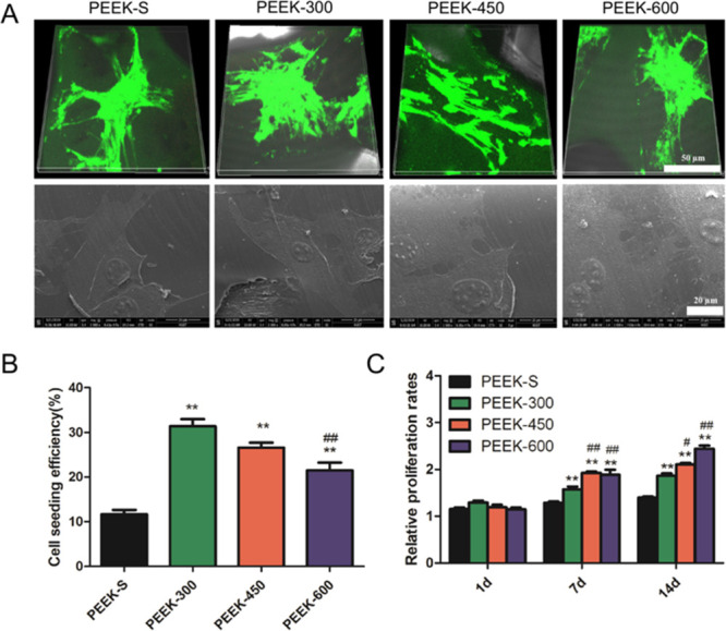
SEM image and fluorescence staining of the morphology of cells on the PEEK scaffold surface. Cell adhesion and proliferation within the PEEK scaffold measurement. (A) Live/Dead staining and SEM images of cells attached to the different PEEK scaffolds after three days of culture (live cells: green and dead cells: red). (B) Cell-seeding efficiency on the different PEEK scaffolds. (C) Relative proliferation rates of cells incubated with different PEEK scaffolds for 1, 7, and 14 days as examined by CCK-8. *P < 0.05 and **P < 0.01 compared with PEEK-S; #P < 0.05 and ##P < 0.01 compared with PEEK-300. The upper images share 50 μm scale bar and the lower images share 20 μm scale bar (A). For each group, n = 3.
In comparison, PEEK-300 displayed the highest cell-seeding efficiency after 24 h culture, with the order of PEEK-300 > PEEK-450 > PEEK-600 > PEEK-S (Figure 4B). Furthermore, the difference between PEEK-300 and PEEK-600 was significant P < 0.01), suggesting that the cell-seeding efficiency decreased with increasing pore size.
Quantitative CCK-8 assessment indicated that hBMSCs continued to grow on all scaffolds from day 7 to day 21 (Figure 4C). At day 7, no difference could be detected between the four groups. However, more cells were loaded within the porous PEEK scaffolds than PEEK-S from day 14 (P < 0.01). In addition, cells on PEEK-450 and PEEK-600 scaffolds exhibited higher viability than those on PEEK-300 (P < 0.05).
3.4. Osteogenic Gene Expression and ALP Staining of hBMSCs in PEEK Scaffolds
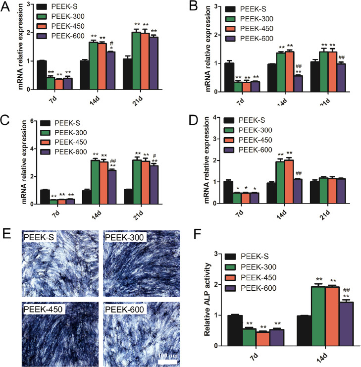
Evaluation of the expression of osteogenesis-related genes (Figure 5A–D) revealed that at day 7, the expression levels of all tested genes (ALP, RUNX2, COL1, and BMP2) on porous PEEK were less than those on PEEK-S with no significant difference among the porous PEEK groups. At day 14, the expression levels of the porous PEEK groups were higher than those of PEEK-S except the levels of RUNX2 and BMP2 on PEEK-600. Among the porous PEEK groups, the expression levels of almost all the genes for PEEK-600 were lower than those for PEEK-300 and PEEK-450 (Figure 5A–D). At day 21, no obvious difference could be determined regarding ALP and BMP2 expression among the porous PEEK groups although the expression of RUNX2 and COL1 for PEEK-300 and PEEK-450 was higher than that of PEEK-600 (Figure 5A–D).
Figure 5.
Osteogenic differentiation as evaluated by osteogenesis-related gene expression and ALP activity. (A–D) Relative expression levels of ALP, RUNX2, COL1, and BMP2 at day 7, 14, and 21. (E) ALP staining results of the cells after culturing with different PEEK scaffolds for 14 days. (F) Relative ALP activity of cells on the different PEEK scaffolds at days 7 and 14. *P < 0.05 and **P < 0.01 compared with PEEK-S; #P < 0.05 and ##P < 0.01 compared with PEEK-300. The images share 100 μm scale bar (E). For each group, n = 3.
As a marker of early osteogenic differentiation, ALP activity was detected at day 7 and day 14 (Figure 5E,F). The ALP activity of the porous PEEK groups was upregulated from day 7 to day 14 in contrast to that of the PEEK-S group. At day 7, the ALP activity of the porous PEEK groups was significantly lower than that of PEEK-S; no significant difference was observed among the porous PEEK groups. Conversely, the ALP activity of the porous PEEK scaffolds was significantly enhanced at day 14 with that of PEEK-300 and PEEK-450 being nearly 2-fold the level of PEEK-S, whereas that of PEEK-600 was approximately 1.5-fold. Furthermore, the ALP activity of PEEK-600 was significantly lower than that of PEEK-300 (Figure 5F). The results of staining for ALP production at day 14 also confirmed this finding (Figure 5E).
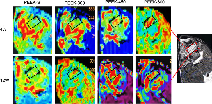
3.5. Microvascular Perfusion Ability
DCE-MRI was used to evaluate vascular perfusion of the porous PEEK scaffolds within the bone defect regions at 4 and 12 weeks following implantation. The MRI images revealed the maximum SI of each group based on the time–signal curves acquired in the ROI. Little blood perfusion was observed in the PEEK-S group at 4 and 12 weeks, whereas this increased with the healing time in the three porous groups; furthermore, the blood perfusion of the PEEK-450 group was significantly higher than that of the PEEK-300 and PEEK-600 groups (Figure 6). The average ME of the PEEK-600 and PEEK-450 groups at 4 weeks was 1.70 ± 0.13 and 1.66 ± 0.08, respectively; these did not significantly differ but were significantly greater than that of PEEK-300 (0.84 ± 0.06). The average ME of the PEEK-450 group at 12 weeks was 2.41 ± 0.26, which was significantly greater than that of PEEK-300 (0.94 ± 0.05) and PEEK-600 (1.96 ± 0.09) (Figure S1).
Figure 6.
MRI images of SI in this distal femur of the rabbits at 4 and 12 weeks after implantation with different PEEK scaffolds. Red represents blood perfusion; black rectangle represents the bone defect site.
3.6. In vivo Bone Regeneration Ability
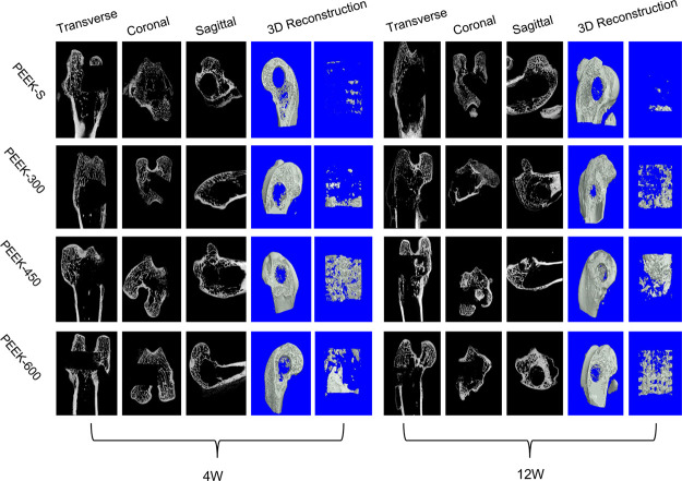
Micro-CT was utilized to evaluate new bone formation of the porous PEEK scaffolds within the bone defect regions at 4 and 12 weeks following scaffold implantation in the distal femoral defect rabbit model. The 2D (transverse, coronal, and sagittal) and 3D reconstruction images of the bone defect tunnel demonstrated that the bone formation of PEEK scaffolds increased with time except for the PEEK-S group (Figure 7). Furthermore, the PEEK-450 group exhibited more bone formation compared to that of the other two groups at 4 and 12 weeks after surgery. The percentage of bone volume (BV/TV), which represents the total new bone formation of the porous scaffolds, demonstrated the same tendency (Figure S2). All porous scaffolds exhibited a markedly higher percentage of BV/TV than that of PEEK-S after implantation for 4 weeks. Among the porous scaffolds, the percentage of BV/TV of the PEEK-450 (4.3 ± 0.3%) and PEEK-600 (3.6 ± 0.2%) groups did not differ significantly but was higher than that of the PEEK-300 group (0.9 ± 0.1%). As the healing time advanced to 12 weeks, all porous scaffold groups still exhibited significantly a higher percentage of BV/TV than that of the PEEK-S group (P < 0.05). Nevertheless, the PEEK-450 showed superior bone ingrowth ability compared to that of the other groups, with the average BV/TV (10.6 ± 1.5%) being 81.1% greater than that in PEEK-300 (2.0 ± 0.2%) and 33.0% greater than that in PEEK-600 (7.1 ± 0.4%).
Figure 7.
New bone formation of the different PEEK scaffolds as evaluated by micro-CT. 2D (transverse, coronal, and sagittal) radiographs and 3D micro-CT images within a central ROI of 5 mm in diameter of the bone tunnel are shown at 4 and 12 weeks after surgery.
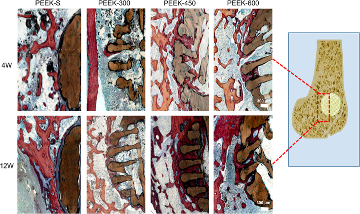
Scaffold osseointegration investigated by histological analysis using H&E staining (Figure 8) revealed the direct bone-to-scaffold contact and that newly formed bone tissues grew into the pore space from the surrounding bone tissue. At 4 and 12 weeks following scaffold implantation, the volume of regenerated bone increased with healing time except in the PEEK-S group, in which the defect was filled with fibrous tissue. Little new bone tissue was formed at the exterior and interior of PEEK-300 scaffolds. In the PEEK-600 group, the external pore spaces were filled with some new bone, whereas little new bone had formed in the inner pores even at 12 weeks. In comparison, the PEEK-450 group exhibited a higher degree of new bone formation at the exterior and interior of the scaffolds. These results suggested that PEEK-450 was favorable for bone ingrowth, which was consistent with the micro-CT results.
Figure 8.
Histological analysis of bone regeneration after implantation of different PEEK scaffolds for 4 and 12 weeks: representative images show new bone formation around and within the scaffolds as evaluated by H&E staining. Red color represents new (regenerative) bone tissues and dark blue represents fibrous tissue. The images share 300 μm scale bar.
4. Discussion
A major concern of using PEEK in biomedical applications is the lack of biocompatibility and bioactivity.31−33 Several studies have confirmed that surface modification constituted an effective strategy to improve the biological performance of PEEK implants, with introduction of a 3D porous network on the surface able to promote cell adhesion and differentiation. However, the induced residual chemical reagent impeded cell growth and migration.34 In comparison, 3D printing could achieve a porous structure without impeding cell viability and proliferation. Nevertheless, the osteogenic effects of fully porous 3D-printed PEEK scaffolds have not yet been reported. Moreover, the mechanical properties of porous PEEK scaffolds as loadbearing orthopedic implants should be considered. In this study, we investigated the mechanical and biological performance of PEEK scaffolds with three different pore sizes generated using 3D-printing technology with the goal of maintaining a balance between the pore size and the physical and biological properties. Porous PEEK scaffolds with porosity of 60–70% and pore size of 300–600 μm, which covered the range of clinical recommendations, were successfully fabricated using FDM.35 The difference between the designed and measured pore size was 7.3–13.1%, suggesting that the 3D printing approach achieved better control of the porous structure than traditional manufacturing processes. Moreover, FDM-based 3D printing permits modification and fabrication of the PEEK scaffold structure to yield different pore sizes, which is important for clinical application as osseous integration of PEEK depends on the surface composition, surface roughness, and pore structure.36 Finally, the features of low cost, rapid prototyping, high accuracy, and a low error rate of this process are obviously advantageous over those of the traditional technology.
Mechanical characterization revealed that the pore size influenced the mechanical properties of porous PEEK scaffolds. The mean stiffness was significantly reduced with the increase in the pore size. The loadbearing capacity of porous PEEK scaffolds was decreased compared with that of PEEK-S, whereas the Young’s modulus and compressive stress of the three porous groups closely matched that of human trabecular bone, being in the range of 0.01–3 GPa and 2–70 MPa, respectively.14 These values are relevant to the structural application of the scaffolds and constitute an important consideration in PEEK implant design. Specifically, PEEK-600 exhibited a slightly lower fatigue strength than PEEK-300, consistent with the report that larger pores produce more and larger fatigue cracks than small pores and, therefore, might have a negative effect on the fatigue lifespan.26 Notably, these results indicated that the pore size could alter the compressive stress and elastic modulus at similar porosity. Together, the mechanical properties of the porous PEEK scaffolds verified that PEEK-300 and PEEK-450 have the potential to bear greater physiological loads with less risk of failure than PEEK-600. However, our analyses had some limitations. In particular, all mechanical tests were performed in air at room temperature rather than in a more physiological environment.
In vitro experiments confirmed the ability of porous PEEK scaffolds to facilitate cell proliferation and differentiation. Previous reports have shown that the pore size of 300–600 μm was suitable for cell ingrowth in metal implants owing to the requirements of cell size, migration, and transport.37,38 In addition, we considered that the cell ingrowth may be further related to the pore size and the water contact angle. PEEK-450 and PEEK-600 present a smaller water contact angle and higher permeability than PEEK-300 and PEEK-S, which may be beneficial for cell and body fluid suspension. Determination of the cell morphology and viability on the PEEK scaffolds by Live/Dead staining and SEM after three days of cell culture revealed that cell pseudopodia adhesion to the surface could be observed on all porous scaffolds. Furthermore, numerous green-stained live cells and few red-stained dead cells were present on the surface, suggesting that all of the tested PEEK scaffolds were biocompatible. Quantitative CCK-8 analysis revealed that scaffolds with large pores exhibited higher permeability but lower cell-seeding efficiency, likely because the large pores allowed the cells to take less time to attach to the surface because of the high average fluid velocity.39 These results may also result from the “curvature-driven growth” mechanism, by which cells can sense the surface tension and tend to maximally reduce the curvature.40 Finally, with regard to cell migration to an inner space, a porous structure with a more surface area will exhibit higher cell viability.41 In our study, porous scaffolds of PEEK-300 provided a larger surface area for cell adhesion. However, the proliferation rates of PEEK-450 and PEEK-600 were significantly higher than that of PEEK-300 after 14 days, suggesting that a larger pore size is more appropriate for cell penetration and proliferation. This may arise because a larger open space is conducive to cell ingrowth and substantial transport of nutrients and oxygen.39,42 Taking these findings into consideration, we suggest that the moderate pore size of approximately 450 μm provides optimal parameters for clinical implants balanced with beneficial mechanical properties and favorable cytocompatibility.
We also evaluated osteogenic differentiation on porous PEEK scaffolds. The ALP activity of the porous PEEK scaffolds was lower than that of the PEEK-S at day 7, in accordance with the expression of bone-related genes, which suggested that osteogenic differentiation of the cells within the porous PEEK scaffolds may be delayed in the initial stage. This may occur because although cell differentiation is caused by mechanical biological stimulation, cell sensing of the stimulation afforded by porous PEEK may be delayed because of the excessive space.43,44 However, the ALP activity and expression of osteogenic differentiation-associated genes were higher for porous PEEK scaffolds than those for PEEK-S at day 14, suggesting that cells on the porous PEEK scaffolds began to differentiate, whereas those on PEEK-S progressed into the late differentiation phase. For the three porous groups, the ALP activity and expression of osteogenic genes in PEEK-600 were lower than those for PEEK-300 and PEEK-450 at day 14, revealing that PEEK-600 may delay the osteogenic differentiation of hBMSCs, consistent with the results of ALP staining. The observation that a relatively small pore size is beneficial for osteogenic differentiation may also be explained by the mechanobiological stimuli hypothesis. Furthermore, the scaffolds with small pore sizes offered an advantage with respect to higher surface area and higher curvature, which were shown to induce higher tissue amplification in vitro.40
Investigation of the bone ingrowth of the porous PEEK scaffolds in vivo revealed that more new bones were formed in the PEEK-450 compared with the PEEK-300 and PEEK-600 groups according to micro-CT together with histological data, with the ranking of newly formed bones being PEKK-S < PEKK-300 < PEEK-600 < PEEK-450 following implantation for 12 weeks. Previous reports indicated that the optimal pore size for attachment, differentiation, and growth of osteoblasts and vascularization is approximately 300–400 μm in vivo.45 Our study also confirmed that an interconnected porous structure could promote bone ingrowth; furthermore, a suitable pore size and high interconnectivity could enhance the bone ingrowth of the PEEK materials, which was consistent with the previous studies.46 Moreover, it has been reported that pore features (size and depth) have a greater effect than smooth surfaces on cell growth and osteogenic capacity.47 In our study, less new bone was regenerated in PEEK-300 although this scaffold exhibited higher bone-related gene expression in vitro at day 14, which indicated that the pore size of 300 μm may be more appropriate for earlier osseointegration, whereas the larger pore sizes of 450 and 600 μm supported more bone regeneration at a later stage. This may suggest that larger pore sizes (>300 μm) are more conducive to nutrient and oxygen exchange, which could promote the process of bone ingrowth and vascularization.48 Together, these observations indicated that PEEK-300 promotes cell attachment and proliferation, which may lead to early osseointegration on the surface whereas PEEK-450 and PEEK-600 allow more bone formation and vascular ingrowth to the inner scaffold.
Vascular ingrowth and sufficient blood flow play an important role during the healing process of bone defects.49 High blood perfusion supports the provision of more nutrition for bone regeneration. PEEK-450 and PEEK-600 scaffolds exhibited a pore size exceeding 300 μm and high inner connectivity of 60% porosity, which are similar to the characteristics of human trabecular bone and is favorable for new vessel ingrowth. The data of DCE-MRI further confirmed that PEEK-450 and PEEK-600 scaffolds mediated better blood perfusion in the early stage than the PEEK-300 scaffold, with the blood perfusion level in the PEEK-450 group being higher than that in both PEEK-300 and PEEK-600 groups at 12 weeks. Consistent with the micro-CT results, the porous architecture together with the appropriate pore size of the PEEK-450 group mediated good vessel function. The sufficient blood flow and nutrition supply would be expected to stimulate cell proliferation and differentiation, ultimately promoting new bone formation.50
5. Conclusions
In summary, three types of porous PEEK scaffolds with different pore sizes were designed and fabricated using a 3D-printing technique. SEM analysis revealed the well-defined pore distribution and inherent interconnectivity throughout the scaffolds. Compression tests demonstrated that the mechanical properties could closely match those of human trabecular bone. In vitro results suggested that the proliferation and differentiation of hBMSCs on the scaffolds were related to pore size, with porous PEEK scaffolds with relatively small pores (PEEK-300 and PEEK-450) being beneficial for cell adhesion and osteogenic differentiation, whereas those with relatively large pores (PEEK-450 and PEEK-600) were more inclined to promote cell proliferation. In vivo findings indicated that PEEK-450 scaffolds with a pore size of approximately 450 μm showed preferential potential for bone ingrowth and vascular perfusion. Thus, although numerous additional geometric parameters (e.g., pore shape and porosity) likely influence the bone ingrowth of porous PEEK implants, these findings provide a sound basis to support patient-specific design and fabrication of porous PEEK implants with suitable geometries to promote bone ingrowth for clinical applications.
Acknowledgments
This work was supported by the National Key Research and Development Program of China (2018YFB1105700), National Natural Science Foundation of China (81772401, 81902260, and U1603121), and Natural Science Foundation of Hubei Province (WJ2017Z016).
Glossary
Abbreviations
- 3D
three-dimensional
- ALP
alkaline phosphatase
- BMP-2
bone morphogenetic protein-2
- BV/TV
bone volume/tissue volume
- COL-1
collagen type I
- CT
computed tomography
- DCE-MRI
dynamic contrast-enhanced magnetic resonance imaging
- FDM
fused deposition modeling
- GAPDH
glyceraldehyde 3 phosphate dehydrogenase
- H&E
hematoxylin & eosin
- hBMSC
human bone marrow mesenchymal stem cell
- ME
maximum enhancement
- PBS
phosphate buffered saline
- PCR
polymerase chain reaction
- PEEK
polyetheretherketone
- PEEK-S
smooth solid polyetheretherketone cylinder
- ROI
region of interest
- RUNX2
runt-related transcription factor-2
- SEM
scanning electron microscopy
Supporting Information Available
The Supporting Information is available free of charge at https://pubs.acs.org/doi/10.1021/acsomega.0c03489.
The average ME of the PEEK-600 and PEEK-450 groups at 4 weeks showed no significant difference, and both of them were significantly greater than that of PEEK-300. The average ME of the PEEK-450 group at 12 weeks was significantly greater than those of PEEK-300 and PEEK-600. The PEEK-450 group exhibited more bone formation compared to that of PEEK-300 and PEEK-600 groups at 4 and 12 weeks after surgery (PDF)
Author Contributions
§ X.F., L.M., and H.L. co-first authors.
Author Contributions
The manuscript was written through contributions of all authors. All authors have given approval to the final version of the manuscript. C.Y. designed and supported the research. X.F., L.M., and H.L. carried out the scaffold fabrication and characterization; X.F., L.M., X.L., J.L., W.L., K.W., Y.S., B.W., Rongjin Luo, Zhiwei Liao, G.L., and S.L. conducted the cell experiments and performed the animal surgeries. X.F. and L.M. drafted the manuscript.
The authors declare no competing financial interest.
Supplementary Material
References
- Chen G.; Matsuhisa N.; Liu Z.; Qi D.; Cai P.; Jiang Y.; Wan C.; Cui Y.; Leow W. R.; Liu Z.; et al. Plasticizing Silk Protein for On-Skin Stretchable Electrodes. Adv. Mater. 2018, 30, 1800129. 10.1002/adma.201800129. [DOI] [PubMed] [Google Scholar]
- Arreaga-Salas D. E.; Avendaño-Bolívar A.; Simon D.; Reit R.; Garcia-Sandoval A.; Rennaker R. L.; Voit W. Integration of High-Charge-Injection-Capacity Electrodes onto Polymer Softening Neural Interfaces. ACS Appl. Mater. Interfaces 2015, 7, 26614–26623. 10.1021/acsami.5b08139. [DOI] [PubMed] [Google Scholar]
- Takizawa T.; Nakayama N.; Haniu H.; Aoki K.; Okamoto M.; Nomura H.; Tanaka M.; Sobajima A.; Yoshida K.; Kamanaka T.; et al. Titanium Fiber Plates for Bone Tissue Repair. Adv. Mater. 2018, 30, 1703608. 10.1002/adma.201703608. [DOI] [PubMed] [Google Scholar]
- Nardi C.; Borri C.; Regini F.; Calistri L.; Castellani A.; Lorini C.; Colagrande S. Metal and motion artifacts by cone beam computed tomography (CBCT) in dental and maxillofacial study. Radiol. Med. 2015, 120, 618–626. 10.1007/s11547-015-0496-2. [DOI] [PubMed] [Google Scholar]
- Han X.; Yang D.; Yang C.; Spintzyk S.; Scheideler L.; Li P.; Li D.; Geis-Gerstorfer J.; Rupp F. Carbon Fiber Reinforced PEEK Composites Based on 3D-Printing Technology for Orthopedic and Dental Applications. J. Clin. Med. 2019, 8, 240. 10.3390/jcm8020240. [DOI] [PMC free article] [PubMed] [Google Scholar]
- Wang S.; Yang Y.; Li Y.; Shi J.; Zhou J.; Zhang L.; Deng Y.; Yang W. Strontium/adiponectin co-decoration modulates the osteogenic activity of nano-morphologic polyetheretherketone implant. Colloids Surf., B 2019, 176, 38–46. 10.1016/j.colsurfb.2018.12.056. [DOI] [PubMed] [Google Scholar]
- Phan K.; Hogan J. A.; Assem Y.; Mobbs R. J. PEEK-Halo effect in interbody fusion. J. Clin. Neurosci. 2016, 24, 138–140. 10.1016/j.jocn.2015.07.017. [DOI] [PubMed] [Google Scholar]
- Baştan F. E.; Atiq Ur Rehman M.; Avcu Y. Y.; Avcu E.; Üstel F.; Boccaccini A. R. Electrophoretic co-deposition of PEEK-hydroxyapatite composite coatings for biomedical applications. Colloids Surf., B 2018, 169, 176–182. 10.1016/j.colsurfb.2018.05.005. [DOI] [PubMed] [Google Scholar]
- Johansson P.; Barkarmo S.; Hawthan M.; Peruzzi N.; Kjellin P.; Wennerberg A. Biomechanical, histological, and computed X-ray tomographic analyses of hydroxyapatite coated PEEK implants in an extended healing model in rabbit. J. Biomed. Mater. Res., Part A 2018, 106, 1440–1447. 10.1002/jbm.a.36345. [DOI] [PubMed] [Google Scholar]
- Zhang J.; Wei W.; Yang L.; Pan Y.; Wang X.; Wang T.; Tang S.; Yao Y.; Hong H.; Wei J. Stimulation of cell responses and bone ingrowth into macro-microporous implants of nano-bioglass/polyetheretherketone composite and enhanced antibacterial activity by release of hinokitiol. Colloids Surf., B 2018, 164, 347–357. 10.1016/j.colsurfb.2018.01.058. [DOI] [PubMed] [Google Scholar]
- Bai H.; Wang D.; Delattre B.; Gao W.; De Coninck J.; Li S.; Tomsia A. P. Biomimetic gradient scaffold from ice-templating for self-seeding of cells with capillary effect. Acta Biomater. 2015, 20, 113–119. 10.1016/j.actbio.2015.04.007. [DOI] [PMC free article] [PubMed] [Google Scholar]
- Yuan B.; Cheng Q.; Zhao R.; Zhu X.; Yang X.; Yang X.; Zhang K.; Song Y.; Zhang X. Comparison of osteointegration property between PEKK and PEEK: Effects of surface structure and chemistry. Biomaterials 2018, 170, 116–126. 10.1016/j.biomaterials.2018.04.014. [DOI] [PubMed] [Google Scholar]
- Evans N. T.; Torstrick F. B.; Lee C. S. D.; Dupont K. M.; Safranski D. L.; Chang W. A.; Macedo A. E.; Lin A. S. P.; Boothby J. M.; Whittingslow D. C.; et al. High-strength, surface-porous polyether-ether-ketone for load-bearing orthopedic implants. Acta Biomater. 2015, 13, 159–167. 10.1016/j.actbio.2014.11.030. [DOI] [PMC free article] [PubMed] [Google Scholar]
- Li F.; Li J.; Xu G.; Liu G.; Kou H.; Zhou L. Fabrication, pore structure and compressive behavior of anisotropic porous titanium for human trabecular bone implant applications. J. Mech. Behav. Biomed. Mater. 2015, 46, 104–114. 10.1016/j.jmbbm.2015.02.023. [DOI] [PubMed] [Google Scholar]
- Lai Y.; Li Y.; Cao H.; Long J.; Wang X.; Li L.; Li C.; Jia Q.; Teng B.; Tang T.; et al. Osteogenic magnesium incorporated into PLGA/TCP porous scaffold by 3D printing for repairing challenging bone defect. Biomaterials 2019, 197, 207–219. 10.1016/j.biomaterials.2019.01.013. [DOI] [PubMed] [Google Scholar]
- Ma H.; Feng C.; Chang J.; Wu C. 3D-printed bioceramic scaffolds: From bone tissue engineering to tumor therapy. Acta Biomater. 2018, 79, 37–59. 10.1016/j.actbio.2018.08.026. [DOI] [PubMed] [Google Scholar]
- Zhakeyev A.; Wang P.; Zhang L.; Shu W.; Wang H.; Xuan J. Additive Manufacturing: Unlocking the Evolution of Energy Materials. Adv. Sci. 2017, 4, 1700187. 10.1002/advs.201700187. [DOI] [PMC free article] [PubMed] [Google Scholar]
- Stansbury J. W.; Idacavage M. J. 3D printing with polymers: Challenges among expanding options and opportunities. Dent. Mater. 2016, 32, 54–64. 10.1016/j.dental.2015.09.018. [DOI] [PubMed] [Google Scholar]
- Zhao F.; Li D.; Jin Z. Preliminary Investigation of Poly-Ether-Ether-Ketone Based on Fused Deposition Modeling for Medical Applications. Materials 2018, 11, 288. 10.3390/ma11020288. [DOI] [PMC free article] [PubMed] [Google Scholar]
- Deng X.; Zeng Z.; Peng B.; Yan S.; Ke W. Mechanical Properties Optimization of Poly-Ether-Ether-Ketone via Fused Deposition Modeling. Materials 2018, 11, 216. 10.3390/ma11020216. [DOI] [PMC free article] [PubMed] [Google Scholar]
- Ramu M.; Ananthasubramanian M.; Kumaresan T.; Gandhinathan R.; Jothi S. Optimization of the configuration of porous bone scaffolds made of Polyamide/Hydroxyapatite composites using Selective Laser Sintering for tissue engineering applications. Bio Med. Mater. Eng. 2018, 29, 739–755. 10.3233/bme-181020. [DOI] [PubMed] [Google Scholar]
- Wieding J.; Lindner T.; Bergschmidt P.; Bader R. Biomechanical sility of novel mechanically adapted open-porous titanium scaffolds in metatarsal bone defects of sheep. Biomaterials 2015, 46, 35–47. 10.1016/j.biomaterials.2014.12.010. [DOI] [PubMed] [Google Scholar]
- Chang B.; Song W.; Han T.; Yan J.; Li F.; Zhao L.; Kou H.; Zhang Y. Influence of pore size of porous titanium fabricated by vacuum diffusion bonding of titanium meshes on cell penetration and bone ingrowth. Acta Biomater. 2016, 33, 311–321. 10.1016/j.actbio.2016.01.022. [DOI] [PubMed] [Google Scholar]
- Tan K. H.; Chua C. K.; Leong K. F.; Naing M. W.; Cheah C. M. Fabrication and characterization of three-dimensional poly(ether- ether- ketone)/-hydroxyapatite biocomposite scaffolds using laser sintering. Proc. Inst. Mech. Eng., Part H 2005, 219, 183–194. 10.1243/095441105x9345. [DOI] [PubMed] [Google Scholar]
- Oh S. H.; Park I. K.; Kim J. M.; Lee J. H. In vitro and in vivo characteristics of PCL scaffolds with pore size gradient fabricated by a centrifugation method. Biomaterials 2007, 28, 1664–1671. 10.1016/j.biomaterials.2006.11.024. [DOI] [PubMed] [Google Scholar]
- Ishihara S.; McEvily A. J.; Goshima T.; Kanekasu K.; Nara T. On fatigue lifetimes and fatigue crack growth behavior of bone cement. J. Mater. Sci.: Mater. Med. 2000, 11, 661–666. 10.1023/a:1008978302196. [DOI] [PubMed] [Google Scholar]
- Xu K.; Ganapathy K.; Andl T.; Wang Z.; Copland J. A.; Chakrabarti R.; Florczyk S. J. 3D porous chitosan-alginate scaffold stiffness promotes differential responses in prostate cancer cell lines. Biomaterials 2019, 217, 119311. 10.1016/j.biomaterials.2019.119311. [DOI] [PubMed] [Google Scholar]
- Ma L.; Feng X.; Wang K.; Song Y.; Luo R.; Yang C. Dexamethasone promotes mesenchymal stem cell apoptosis and inhibits osteogenesis by disrupting mitochondrial dynamics. FEBS Open Bio 2019, 10, 211–220. 10.1002/2211-5463.12771. [DOI] [PMC free article] [PubMed] [Google Scholar]
- Song Y.; Li S.; Geng W.; Luo R.; Liu W.; Tu J.; Wang K.; Kang L.; Yin H.; Wu X.; et al. Sirtuin 3-dependent mitochondrial redox homeostasis protects against AGEs-induced intervertebral disc degeneration. Redox Biol. 2018, 19, 339–353. 10.1016/j.redox.2018.09.006. [DOI] [PMC free article] [PubMed] [Google Scholar]
- Wang K.; Zha Y.; Lei H.; Xu X. MRI Study on the Changes of Bone Marrow Microvascular Permeability and Fat Content after Total-Body X-Ray Irradiation. Radiat. Res. 2018, 189, 205–212. 10.1667/rr14865.1. [DOI] [PubMed] [Google Scholar]
- Zhang J.; Tian W.; Chen J.; Yu J.; Zhang J.; Chen J. The application of polyetheretherketone (PEEK) implants in cranioplasty. Brain Res. Bull. 2019, 153, 143–149. 10.1016/j.brainresbull.2019.08.010. [DOI] [PubMed] [Google Scholar]
- Zhu Y.; Cao Z.; Peng Y.; Hu L.; Guney T.; Tang B. Facile Surface Modification Method for Synergistically Enhancing the Biocompatibility and Bioactivity of Poly(ether ether ketone) That Induced Osteodifferentiation. ACS Appl. Mater. Interfaces 2019, 11, 27503–27511. 10.1021/acsami.9b03030. [DOI] [PubMed] [Google Scholar]
- Lu T.; Wen J.; Qian S.; Cao H.; Ning C.; Pan X.; Jiang X.; Liu X.; Chu P. K. Enhanced osteointegration on tantalum-implanted polyetheretherketone surface with bone-like elastic modulus. Biomaterials 2015, 51, 173–183. 10.1016/j.biomaterials.2015.02.018. [DOI] [PubMed] [Google Scholar]
- Torstrick F. B.; Evans N. T.; Stevens H. Y.; Gall K.; Guldberg R. E. Do Surface Porosity and Pore Size Influence Mechanical Properties and Cellular Response to PEEK?. Clin. Orthop. Relat. Res. 2016, 474, 2373–2383. 10.1007/s11999-016-4833-0. [DOI] [PMC free article] [PubMed] [Google Scholar]
- Karageorgiou V.; Kaplan D. Porosity of 3D biomaterial scaffolds and osteogenesis. Biomaterials 2005, 26, 5474–5491. 10.1016/j.biomaterials.2005.02.002. [DOI] [PubMed] [Google Scholar]
- Zhao Y.; Wong H. M.; Lui S. C.; Chong E. Y. W.; Wu G.; Zhao X.; Wang C.; Pan H.; Cheung K. M. C.; Wu S.; et al. Plasma Surface Functionalized Polyetheretherketone for Enhanced Osseo-Integration at Bone-Implant Interface. ACS Appl. Mater. Interfaces 2016, 8, 3901–3911. 10.1021/acsami.5b10881. [DOI] [PubMed] [Google Scholar]
- Fukuda A.; Takemoto M.; Saito T.; Fujibayashi S.; Neo M.; Pattanayak D. K.; Matsushita T.; Sasaki K.; Nishida N.; Kokubo T.; et al. Osteoinduction of porous Ti implants with a channel structure fabricated by selective laser melting. Acta Biomater. 2011, 7, 2327–2336. 10.1016/j.actbio.2011.01.037. [DOI] [PubMed] [Google Scholar]
- Taniguchi N.; Fujibayashi S.; Takemoto M.; Sasaki K.; Otsuki B.; Nakamura T.; Matsushita T.; Kokubo T.; Matsuda S. Effect of pore size on bone ingrowth into porous titanium implants fabricated by additive manufacturing: An in vivo experiment. Mater. Sci. Eng. C 2016, 59, 690–701. 10.1016/j.msec.2015.10.069. [DOI] [PubMed] [Google Scholar]
- Van Bael S.; Chai Y. C.; Truscello S.; Moesen M.; Kerckhofs G.; Van Oosterwyck H.; Kruth J.-P.; Schrooten J. The effect of pore geometry on the in vitro biological behavior of human periosteum-derived cells seeded on selective laser-melted Ti6Al4V bone scaffolds. Acta Biomater. 2012, 8, 2824–2834. 10.1016/j.actbio.2012.04.001. [DOI] [PubMed] [Google Scholar]
- Knychala J.; Bouropoulos N.; Catt C. J.; Katsamenis O. L.; Please C. P.; Sengers B. G. Pore geometry regulates early stage human bone marrow cell tissue formation and organisation. Ann. Biomed. Eng. 2013, 41, 917–930. 10.1007/s10439-013-0748-z. [DOI] [PubMed] [Google Scholar]
- Di Santo R.; Digiacomo L.; Palchetti S.; Palmieri V.; Perini G.; Pozzi D.; Papi M.; Caracciolo G. Microfluidic manufacturing of surface-functionalized graphene oxide nanoflakes for gene delivery. Nanoscale 2019, 11, 2733–2741. 10.1039/c8nr09245a. [DOI] [PubMed] [Google Scholar]
- Chimutengwende-Gordon M.; Dowling R.; Pendegrass C.; Blunn G. Determining the porous structure for optimal soft-tissue ingrowth: An in vivo histological study. PLoS One 2018, 13, e0206228 10.1371/journal.pone.0206228. [DOI] [PMC free article] [PubMed] [Google Scholar]
- Park S. H.; Park S. A.; Kang Y. G.; Shin J. W.; Park Y. S.; Gu S. R.; Wu Y. R.; Wei J.; Shin J.-W. PCL/β-TCP Composite Scaffolds Exhibit Positive Osteogenic Differentiation with Mechanical Stimulation. Tissue Eng. Regener. Med. 2017, 14, 349–358. 10.1007/s13770-017-0022-9. [DOI] [PMC free article] [PubMed] [Google Scholar]
- Zhao L.; Hu L.; Huo K.; Zhang Y.; Wu Z.; Chu P. K. Mechanism of cell repellence on quasi-aligned nanowire arrays on Ti alloy. Biomaterials 2010, 31, 8341–8349. 10.1016/j.biomaterials.2010.07.036. [DOI] [PubMed] [Google Scholar]
- Murphy C. M.; Haugh M. G.; OʼBrien F. J. The effect of mean pore size on cell attachment, proliferation and migration in collagen-glycosaminoglycan scaffolds for bone tissue engineering. Biomaterials 2010, 31, 461–466. 10.1016/j.biomaterials.2009.09.063. [DOI] [PubMed] [Google Scholar]
- Mullen L.; Stamp R. C.; Fox P.; Jones E.; Ngo C.; Sutcliffe C. J. Selective laser melting: a unit cell approach for the manufacture of porous, titanium, bone in-growth constructs, suile for orthopedic applications. II. Randomized structures. J. Biomed. Mater. Res., Part B 2010, 92, 178–188. 10.1002/jbm.b.31504. [DOI] [PubMed] [Google Scholar]
- Gui N.; Xu W.; Abraham A. N.; Myers D. E.; Mayes E. L. H.; Xia K.; Shukla R.; Qian M. A comparative study of the effect of submicron porous and smooth ultrafine-grained Ti-20Mo surfaces on osteoblast responses. J. Biomed. Mater. Res., Part A 2018, 106, 2020–2033. 10.1002/jbm.a.36402. [DOI] [PubMed] [Google Scholar]
- Xue W.; Krishna B. V.; Bandyopadhyay A.; Bose S. Processing and biocompatibility evaluation of laser processed porous titanium. Acta Biomater. 2007, 3, 1007–1018. 10.1016/j.actbio.2007.05.009. [DOI] [PubMed] [Google Scholar]
- Matsumoto T.; Goto D. Effect of low-intensity whole-body vibration on bone defect repair and associated vascularization in mice. Med. Biol. Eng. Comput. 2017, 55, 2257–2266. 10.1007/s11517-017-1664-4. [DOI] [PubMed] [Google Scholar]
- Li T.; Peng M.; Yang Z.; Zhou X.; Deng Y.; Jiang C.; Xiao M.; Wang J. 3D-printed IFN-γ-loading calcium silicate-β-tricalcium phosphate scaffold sequentially activates M1 and M2 polarization of macrophages to promote vascularization of tissue engineering bone. Acta Biomater. 2018, 71, 96–107. 10.1016/j.actbio.2018.03.012. [DOI] [PubMed] [Google Scholar]
Associated Data
This section collects any data citations, data availability statements, or supplementary materials included in this article.


