Abstract
An experimental and theoretical study is reported to investigate the influence of bromine doping on CH3NH3Pb(I1–xBrx)3 perovskite for Br compositions ranging from x = 0 to x = 0.1, in which the material remains in the tetragonal phase. The experimental band gap is deduced from UV–vis absorption spectroscopy and displays a linear behavior as a function of bromine concentration. Density functional theory calculations are performed for five different series of randomly doped structures in order to simulate the disorder in bromine doping sites. The computations predict a linear variation of the lattice parameters, supercell volume, density, band gap, and formation energy in the considered doping range. The calculated evolution of the band gap as the function of Br doping is in excellent agreement with the experimental data, provided that different Br doping configurations are included in the simulations. The analysis of the structural and electronic properties shows a correlation between the increase of the band gap and the increased distortion of the Pb(I1–xBrx)6 octahedrons. Additionally, the simulations suggest that in CH3NH3Pb(I1–xBrx)3 bromine doping is likely to occur at both the equatorial and apical positions of the octahedrons.
1. Introduction
Hybrid organic–inorganic perovskites form a light, low-cost, and easy-to-fabricate class of semiconductor materials.1−3 In 2009, Kojima et al. used for the first time methylammonium lead iodine (MAPbI3) and methylammonium lead bromine (MAPbBr3) as visible-light sensitizers in photoelectrochemical cells, reaching power conversion efficiencies (PCEs) equal to 3.81 and 3.13%, respectively.4 In the following decade, an exceptional increase of the solar cell efficiency has been obtained with these materials, attaining PCE of about 15–20% using MAPbI3,1,5,6 of 4–8% using MAPbBr3,7,8 and in general up to 26% for perovskite-based solar cells.9
One of the most important differences between MAPbI3 and MAPbBr3 is their band gap width. Both materials show a direct band gap,10,11 but MAPbI3 has a band gap narrower than MAPbBr3, with values of about 1.6 eV11,12 and 2.0–2.2 eV,12,13 respectively. This difference makes mixed lead halide perovskite MAPb(I1–xBrx)3 a highly tunable material, in which the band gap can be modulated by changing the percentage of bromine doping.12,13 The simplicity in tuning the band gap makes this material interesting for applications in tandem solar cells.14,15 Besides, bromine doping leads to increased chemical stability.12 At room temperature, MAPbI3 has a tetragonal phase, whereas MAPbBr3 has a cubic phase.16 As a consequence, MAPb(I1–xBrx)3 is known to undergo a phase transition from the tetragonal phase to the cubic phase for bromine doping larger than 20%.12 It can be mentioned that Br doping shows a behavior opposite to that of Sn doping (replacing Pb atoms), which produces a decrease of the band gap in comparison to the MAPbI3 material.17 This illustrates how easily the MAPbI3 band gap can be tuned by small material changes like doping,18 which is one of the reasons why this class of material is so popular and is widely used in solar cell applications.
Being able to predict the changes in band gap values induced by structural modifications or doping is very important for the design of efficient perovskite materials and can be performed employing computational methods.19 For example, in a previous study on MAPbI3, we investigated the effects of changes in the inorganic frame geometry and the MA cation orientations.11 Considering an ensemble of more than 3000 structures, standard deviations of about 0.1–0.2 eV were estimated for the band gap. Moreover, time-dependent density functional theory (DFT) calculations of the absorption spectrum provided an assignment of three experimental bands, and the impact of structural modifications on the transition energies and intensities was described. In particular, some structures presented a much weaker absorption in the 600–700 nm region compared to structures with nearly similar total energies. Tuning the band gap as well as the electronic and optical properties of MAPbI3 can be achieved by different structural modifications and doping concentrations; in particular, computational investigations have considered: (i) the replacement of the organic MA cation, for example, by formamidinium, Cs+ or Rb+,20−24 (ii) the substitution of Pb, for example, by Sn,25−27 and (iii) the change of iodine by bromine or chlorine.21,28−31
The simulation of the electronic properties of MAPb(I1–xBrx)3 in the tetragonal phase presents a great computational challenge due to the combined organic–inorganic character of this material and due to numerous configurations in which Br doping can occur. Only a few theoretical studies investigated the effects of Br doping on the band gap and the material structure.21,28,30 In particular, Mosconi et al.30 performed DFT calculations on MAPbI2Br and found a good correlation between theory and experiment for the band gap. This study also suggested that bromine atoms are likely to occupy both the apical and equatorial positions of the octahedrons. Moreover, Brivio et al.28 performed a statistical mechanical study of MAPb(I1–xBrx)3 alloys by considering seven different compositions (0 ≤ x ≤ 1) in order to predict the phase diagram. To our knowledge, no study has investigated theoretically the effects of bromine doping on the band gap and the structural properties in the tetragonal phase of MAPb(I1–xBrx)3 for compositions x < 0.2.
In this work, the band gap values are first determined experimentally using absorption spectroscopy for material compositions ranging from x = 0 to x = 0.1. Then, the lattice parameters, band gap, and formation energies are calculated for five different series of doping configurations in the same range of compositions. Such calculations are computationally expensive and require the use of large unit cells (384 atoms in our case) to realistically simulate the disorder in bromine doping sites. This leads to an accurate prediction of the band gap evolution and allows for an investigation of the structure/property relations in this material.
2. Results and Discussion
2.1. Experimental Results
All the perovskite samples were prepared using perovskite precursor solutions with the same concentrations. Therefore, the thicknesses of all perovskite layers are the same and are equal to approximately 470 nm. The structural characterization of the samples is done using the X-ray diffraction (XRD) measurement technique. Figure 1 shows the diffraction patterns for MAPb(I1–xBrx)3, with the Br concentration from 0 to 10%. The highest intensity diffraction peak is (110), which suggests the I4cm tetragonal phase of the perovskite layer.32 The secondary phase of PbI2 is negligible and only observed at 13°, which confirms a very good quality of the crystallized perovskite. It is also observed that the intensity of this peak gradually disappears with an increase of bromine concentration. Also, a higher bromine concentration leads to a change of the perovskite phase from tetragonal to cubic. Noh et al. have shown that this phase transition occurs at approximately 13% of bromine concentration.12 The inset of Figure 1 shows the slight shift of highest intensity peaks (110) and (220) for different perovskite compositions. The gradual substitution of I atoms with smaller Br atoms decreases the lattice spacing, which is visible as the shift of diffraction peak.12 This has other implications in the optical or electrical properties of the material.33 However, this shift would be much larger for a phase transition, which is not observed here.
Figure 1.
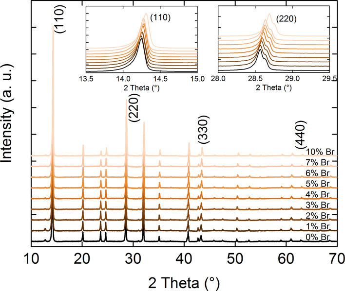
XRD characterization of perovskite samples.
Figure 2 shows the UV–vis absorption spectrum for different bromine atom concentrations. In our last work, Martynow et al.11 assigned the maximum absorption peaks for MAPbI3 without bromine atoms. It is observed that the overall shape of the spectrum is not changed for different doping compositions. However, in Figure 2, it is observed that by increasing the bromine concentration the absorption spectrum is shifted toward higher energies. The addition of bromine atoms is a well-known way of tuning the band gap, which results in the shift of absorption.34 Using the Tauc plot for the calculation of the optical band gaps, it gives values comprised between 1.598 and 1.642 eV for bromine concentrations of 0–10%, respectively. The change of band gap in this range is linear with a step of about 4 meV per percent of bromine concentration.
Figure 2.
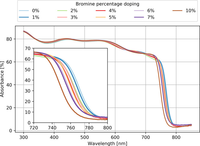
Experimental absorbance of UV–vis light for nine different bromine-doped MAPb(I1–xBrx)3 samples.
2.2. Theoretical Results
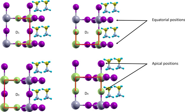
Bromine doping in the hybrid organic–inorganic MAPb(I1–xBrx)3 material has a significant impact on the physical properties, including the lattice parameters (a, b, c), the volume V, the density ρ (Figure 3), the band gap (Figure 6), and the formation energy (Figure 7). The effects of bromine doping were simulated using five different series (S0, S1, S2, S3, and S4) of random Br doping. The behavior of the computed material properties was analyzed by linearly fitting all data series together and of each series separately. The linear fit parameters m and n are reported in Table 1. Moreover, the number of bromine atoms, located in equatorial position (Figure 4) in the Pb(I1–xBrx)6 octahedrons, is given in Table 2 for each series at different doping concentrations. The effects induced by Br doping on the inorganic frame are quantified by four dihedral angles D1, D2, D3, and D4 (Figure 4). The angles D1 and D3 describe the rotations of the octahedrons along the Z crystal axis, whereas D2 and D4 describe the rotations related to the tilting of the octahedrons.11 The mean dihedral angle values (Figure 5) are obtained by averaging over the nine octahedrons in the supercell plane defined by the (−1, 1, 0) Miller index.
Figure 3.
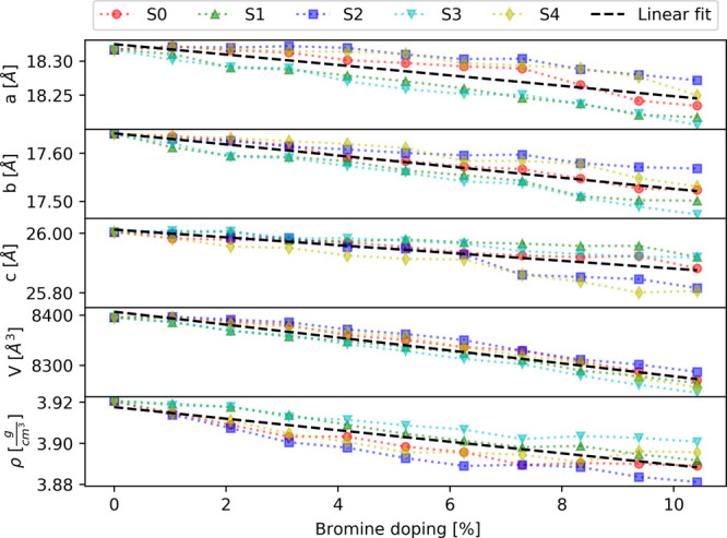
Lattice parameters (a, b, c), volume (V), and density (ρ) of the MAPb(I1–xBrx)3 supercell as the function of bromine doping. The five series of doped structures are indicated by red, green, blue, cyan, and yellow markers. The linear fit is presented by a black dashed line.
Figure 6.
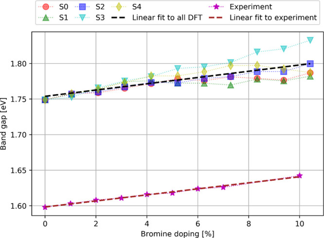
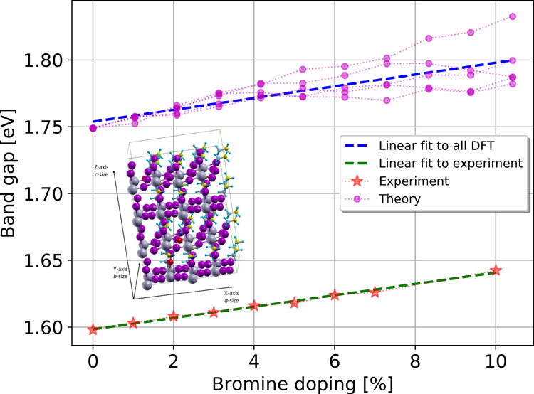
Experimental and theoretical band gap values of MAPb(I1–xBrx)3 as the function of bromine doping. The five calculated series of doped structures are indicated by red, green, blue, cyan, and yellow markers, whereas the experimental values are indicated by magenta stars. The linear fits to theoretical and experimental values are presented by black and brown dashed lines, respectively.
Figure 7.
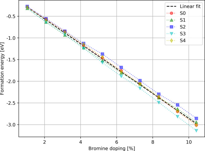
Theoretical formation energies of MAPb(I1–xBrx)3 as the function of bromine doping. The five series of doped structures are indicated by red, green, blue, cyan, and yellow markers. The linear fit is presented by a black dashed line.
Table 1. Linear Fit Parameters m and n (Equation 2) for Each Separate Series of Doped Structures (S0, S1, S2, S3, and S4), and for Their Average (Saverage)a.
|
Saverage |
S0 |
S1 |
S2 |
S3 |
S4 |
|||||||
|---|---|---|---|---|---|---|---|---|---|---|---|---|
| property | m | n | m | n | m | n | m | n | m | n | m | n |
| band gap [eV] | 0.0044 (0.0043) | 1.7538 (1.5983) | 0.0032 | 1.7545 | 0.0024 | 1.7577 | 0.0044 | 1.7516 | 0.0079 | 1.7482 | 0.0042 | 1.7574 |
| a [Å] | –0.008 | 18.325 | –0.008 | 18.333 | –0.010 | 18.318 | –0.005 | 18.330 | –0.010 | 18.315 | –0.006 | 18.330 |
| b [Å] | –0.012 | 17.642 | –0.012 | 17.647 | –0.013 | 17.633 | –0.007 | 17.639 | –0.015 | 17.637 | –0.010 | 17.653 |
| c [Å] | –0.013 | 26.013 | –0.010 | 26.003 | –0.007 | 26.009 | –0.019 | 26.026 | –0.010 | 26.017 | –0.020 | 26.008 |
| volume [Å3] | –12.9 | 8406.0 | –12.4 | 8410.2 | –12.6 | 8398.2 | –11.3 | 8412.1 | –14.5 | 8401.5 | –13.5 | 8413.0 |
| density [g/cm3] | –0.003 | 3.918 | –0.003 | 3.916 | –0.003 | 3.922 | –0.004 | 3.915 | –0.002 | 3.920 | –0.003 | 3.915 |
| formation energy [eV] | –0.287 | 0.010 | –0.291 | 0.044 | –0.277 | –0.057 | –0.275 | 0.024 | –0.300 | 0.005 | –0.289 | 0.036 |
| dihedral 1 [deg] (D1) | –0.027 | 7.647 | –0.034 | 7.490 | –0.046 | 7.600 | 0.008 | 7.701 | –0.054 | 7.861 | –0.006 | 7.586 |
| dihedral 2 [deg] (D2) | 0.023 | 21.061 | 0.005 | 21.253 | –0.018 | 21.360 | 0.050 | 20.784 | 0.045 | 20.990 | 0.033 | 20.916 |
| dihedral 3 [deg] (D3) | –0.014 | 20.180 | 0.0479 | 19.899 | –0.020 | 20.317 | –0.052 | 20.282 | 0.003 | 20.000 | –0.049 | 20.401 |
| dihedral 4 [deg] (D4) | 0.154 | 12.718 | 0.190 | 12.718 | 0.123 | 13.069 | 0.095 | 12.958 | 0.197 | 12.769 | 0.166 | 12.263 |
The experimental values for the band gap are indicated in brackets.
Figure 4.
Definition of the four considered dihedral angles D1, D2, D3, and D4 as well as of the equatorial and apical positions, where Br doping can occur.
Table 2. Number of Bromine Atoms Located in Equatorial Position for the Five Series of Doped Structures.
| number
of Br atoms in equatorial position |
|||||
|---|---|---|---|---|---|
| total number of Br atoms in a series | S0 | S1 | S2 | S3 | S4 |
| 1 | 0 | 1 | 0 | 1 | 0 |
| 2 | 1 | 2 | 1 | 2 | 0 |
| 3 | 1 | 2 | 1 | 2 | 0 |
| 4 | 2 | 3 | 1 | 3 | 0 |
| 5 | 2 | 4 | 2 | 4 | 1 |
| 6 | 3 | 5 | 2 | 5 | 2 |
| 7 | 4 | 6 | 2 | 5 | 2 |
| 8 | 4 | 7 | 3 | 6 | 3 |
| 9 | 5 | 8 | 4 | 7 | 4 |
| 10 | 5 | 8 | 4 | 8 | 5 |
Figure 5.
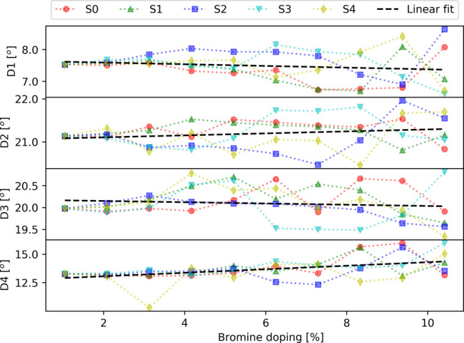
Mean dihedral angles (D1, D2, D3, and D4) as the function of bromine doping. The five series of doped structures are indicated by red, green, blue, cyan, and yellow markers. The linear fit is presented by a black dashed line.
Following the optimization of the supercell with variable-cell relaxation, it is observed that the doped MAPb(I1–xBrx)3 structures remain nearly tetragonal with a ≈ b ≠ c (Figure 3). Overall, the lattice parameters, volume, and density show a linear decrease as the function of bromine doping concentration. This can be understood from the fact that Br doping replaces I–Pb bonds by shorter Br–Pb bonds, which produces a decrease in the supercell volume. These results are in agreement with the shift of the diffraction peak observed in the experiment (see the previous section). Additionally, this effect leads to different evolutions between the series. Thus, series S1 and S3 present a stronger decrease of the a and b parameters, whereas the series S2 and S4 display a faster decrease of the lattice parameter c (Figure 3 and Table 1). This behavior can be explained by the large number of bromine atoms located in equatorial positions (8 atoms out of 10) in the series S1 and S3 (Table 2), which consequently reduces the a and b lattice parameters more in comparison to the other series. The opposite behavior is obtained for the series S2 and S4 due to the significant number of Br atoms located in apical positions (6 and 5 atoms out of 10). The supercell volume presents a larger decrease for series S3, and the smallest decrease is obtained for series S2 (Figure 3 and Table 1), which indicates that Br doping in equatorial positions has a larger effect on the volume. Consequently, the inverse trend is observed for the density. The mean dihedral angles (Figure 5 and Table 1) present different behaviors as the function of bromine doping. Indeed, on average, the dihedral angles D2 and D4 increase with a larger Br doping, whereas D1 and D3 show a slight decrease. However, the different series display a significant dispersion in the dihedral angle values, which increases with the percentage of Br doping. This indicates that the mean dihedral angles are very sensitive to the choice of a particular doping site as well as to the overall configuration of Br atom positions.
Figure 6 presents the evolution of the experimental and theoretical band gaps as the function of bromine doping. The calculated band gap is slightly overestimated by about 0.15 eV in comparison to the experimental results. Such an accuracy is expected at this level of theory for MAPb(I1–xBrx)3 and stays in agreement with our previous results on MAPbI3.11 Both experimental and theoretical results show that the band gap increases linearly for bromine doping ranging from 0 to 10%. It can be mentioned that previous experimental results12 have demonstrated that the band gap displays a quadratic behavior as a function of bromine composition in the entire 0–100% doping range. However, in the 0–10% doping range, which corresponds to the tetragonal phase, the band gap evolution is nearly linear. As seen from Figure 6, the evolution of the calculated average band gap as a function of Br doping is in excellent agreement with the experimental results. This is illustrated by the calculated average slope m equal to 0.0044 eV/% (see Table 1), which agrees almost perfectly with the experimental value of 0.0043 eV/%. However, significant differences are observed for each series separately, in particular with slopes ranging from 0.0024 eV/% for S1 to 0.0079 eV/% for S3, as shown in Table 1. This highlights the importance of averaging over several doping configurations to properly reproduce the experimental trend. The series S1 and S3 present the largest deviations from the average slope, with S3 overestimating and S1 underestimating the band gap slope. These two series also possess the largest number of Br atoms in equatorial positions (Table 2), which shows that (i) bromine doping at the equatorial positions can lead to an opposite effect on the band gap value and (ii) structures with a dominant proportion of equatorial Br atoms do not reproduce the correct band gap evolution. In contrast, structures with a nearly equal proportion of equatorial and apical bromine atoms display a better agreement with the experimental band gap evolution, as illustrated in particular by the series S2 and S4 having slopes of 0.0044 and 0.0042 eV/%, respectively (Table 1). Furthermore, the data reveal a correlation between the band gap and the variation of the mean dihedral angles describing the distortion of the octahedron. In particular, a larger tilting of the octahedrons (estimated by D2 and D4) leads to larger band gap values. Such correlation was already mentioned in previous works concerning other perovskite materials (see e.g., ref (22)). This effect can be interpreted by the fact that the distortion of the octahedrons affects the stabilities of the highest occupied p(I/Br)s(Pb) and the lowest unoccupied p(Pb) orbitals,11 which consequently leads to an increase of the band gap values.
Figure 7 presents the evolution of the formation energy as the function of bromine doping. The series S3 leads to more stable structures, whereas the series S2 to the less stable. This indicates that doping at the equatorial positions produces more stable structures than doping at the apical position. However, the values of the formation energies are very close to the other series, which suggests that the mixing of apical and equatorial doping is more likely to occur in the real material. This observation is in agreement with the theoretical study of Mosconi et al.30
3. Conclusions
The effects of bromine doping on MAPb(I1–xBrx)3 were investigated experimentally and theoretically for Br compositions ranging from x = 0 to x = 0.1. The structural characterization performed with XRD measurements confirmed the tetragonal phase of MAPb(I1–xBrx)3 in this doping range. The effect of doping on the band gap was obtained from UV–vis absorption spectroscopy, which demonstrated a linear increase of the band gap as the function of bromine concentration, with an estimated slope of 0.0043 eV/%. DFT calculations were performed using a large supercell of 384 atoms in order to simulate the disorder in bromine doping. To this aim, five different series of random doping configurations were computed. The calculations predict a linear evolution of the lattice parameters (a, b, c), volume, density, band gap, and formation energy in the considered doping range. The differences between the series for the lattice parameters, volume, and density can be related to doping of Br atoms at the apical or equatorial positions (i.e., doping at the equatorial position has a stronger impact on the a and b parameters, whereas doping at the apical position leads to a larger decrease of the c parameter). A systematic overestimation of about 0.15 eV is obtained for the band gap in comparison to the experimental values. However, the evolution of the average band gap as the function of Br doping (calculated slope of 0.0044 eV/%) is in excellent agreement with the experimental results (slope of 0.0043 eV/%). This demonstrates that the employed computational methods are suitable to predict the effects of Br doping on this material. In particular, the differences in band gap values between the series show the importance of including several doping configurations in the simulation in order to correctly reproduce the experimental behavior. Moreover, the analysis of the band gap values and formation energies for the different series suggests that the mixing of Br doping at both the apical and equatorial positions is more likely in the MAPb(I1–xBrx)3 material. Finally, the calculation of the dihedral angles reveals a correlation between the band gap and the distortion of the Pb(I1–xBrx)6 octahedrons.
4. Experimental and Computational Methods
4.1. Experimental Section
MAPb(I1–xBrx)3 precursors with 0–10% bromine concentration were prepared using commercial lead iodide (PbI2) from TCI (99.99%), methylammonium iodine (MAI) powder from GreatCell Solar, methylammonium bromine (MABr) from Lintec (99.5%), dimethylformamide (DMF) solvent from Sigma-Aldrich (99.8%), and 1-methyl-2-pyrrolidinone (NMP) solvent from Acros Organics (99.5%). Two stock precursors were prepared by mixing PbI2 and MAI and also PbI2 and MABr. The mixtures were further dissolved in DMF/NMP (9:1) solvents with an equimolar ratio of 1.2 M. The 0–10% bromine concentration precursors were made by mixing these two stock solutions.
The glass substrates were cleaned in an ultrasonic bath using soap water, deionized water, and isopropanol and also UV–ozone-treated for 30 min. The samples were spin-coated inside a N2 glovebox, with the oxygen and moisture levels at approximately 1 ppm. The perovskite layers were prepared using the gas quenching method.6,11 The precursor was dynamically spin-coated by starting with a rotational speed of 2000 rpm for 10 s with an acceleration of 200 rpm s–1, which was further accelerated to 5000 rpm for 30 s with 2000 rpm s–1. After 15 s, a nitrogen gun was used to quench the perovskite layer for 15 s. After quenching, the samples were annealed on the hot-plate at 100 °C for 10 min.
The layer thickness was measured with a Bruker DektakXT profiler. The structural analysis was performed using an X-ray diffractometer from PANalytical Empyrean. The UV–vis measurements were done with a spectrophotometer (Agilent Cary 5000), where the transmittance (T) and the reflectance (R) were measured using an integrating sphere to find the absorbance of the samples (100% = A + T + R).
4.2. Theoretical Methods
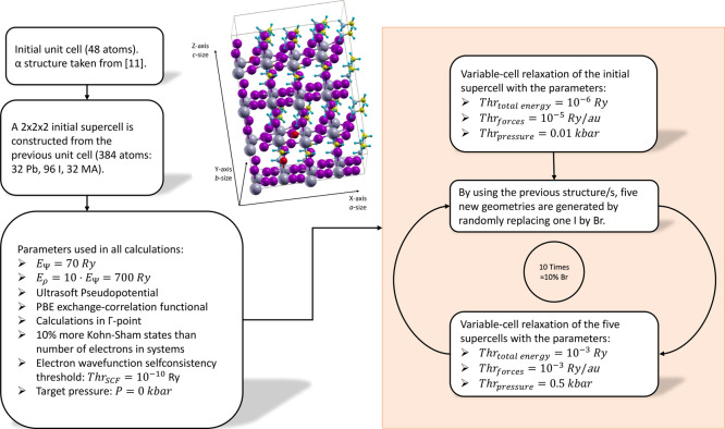
The computational procedure employed to construct and optimize the MAPb(I1–xBrx)3 structures is summarized in Figure 8. A 2 × 2 × 2 supercell containing 384 atoms (32 Pb, 96 I, 32 MA) is constructed using an initial tetragonal unit cell (48 atoms) optimized in our previous study11 (denoted as α structure). The α structure provides the lowest total energy, with the band gap close to the experimental value, and it gives a good reproduction of the absorption spectrum.11 The geometry of the initial 2 × 2 × 2 supercell is then optimized using DFT variable-cell relaxation by applying the computational parameters summarized in Figure 8. These input parameters were chosen to obtain a good compromise between computational cost and accuracy. Indeed, benchmark calculations have shown that computational errors on the total energy and band gap are lower than 10–3 Ry and 10–3 eV, respectively, which give a sufficient accuracy for the prediction of structures and band gaps. The initial supercell relaxation was performed with tight thresholds on the total energy, forces, and pressure (see the right column of Figure 8). This provides a well-optimized structure, on which further calculations will be based on.
Figure 8.
Diagram describing the computational process. Left column: initial unit cell and summary of the calculation parameters. Right column: DFT optimization of MAPb(I1–xBrx)3 structures.
Then, an iterative procedure was employed to generate five series of doped structures. Starting from the initial supercell, five new structures are generated by randomly replacing one I atom with one Br atom. These five structures are then optimized with variable-cell relaxation using the thresholds reported in Figure 8. As the initial supercell contains 96 iodine atoms, the replacement of one I with Br provides doping of approximately 1%. In the next iterations, an additional I atom is randomly substituted by a Br atom in the five previously optimized structures, and variable-cell relaxations are performed. The process is repeated 10 times to cover a doping range from 0% to about 10%. The use of this iterative approach is important because it reduces the computational cost of the geometry optimizations and avoids convergence problems, which occur when the initial supercell is doped with more than one Br atom at a time.
The theoretical investigation was performed with the open-source Quantum ESPRESSO (QE) package, version 6.4.1.,35 which provides well-parallelized plane-wave basis set DFT programs. In general, all calculations use the same computational parameter framework. The Perdew–Burke–Ernzerhof generalized gradient approximation to the exchange–correlation functional36 was employed. The kinetic energy cutoffs for the wave function (EΨ) and charge density (Eρ) were set to 70 and 700 Ry, respectively. The self-consistency of the electronic wave function was achieved with the Davidson algorithm37 using a threshold of 10–10 Ry. Variable-cell relaxations (in which the lattice parameters a, b, and c are optimized) of the supercell structures were performed with the Broyden–Fletcher–Goldfarb–Shanno38 method. Thresholds for the total energy, forces, and pressure were equal to 10–6 Ry, 10–5 Ry/au, and 0.01 kbar for the initial supercell, whereas they were chosen as 10–3 Ry, 10–3 Ry/au, and 0.50 kbar for the doped supercells (Figure 8). The target pressure during variable-cell relaxation was set to 0.00 kbar.
Additionally, the computational costs of the Blöchl projector augmented wave (PAW)39 method and of the Vanderbilt ultrasoft pseudopotentials40 (USPP) were compared. Furthermore, similar tests were performed with the van der Waals exchange-hole dipole moment (XDM) model,41,42 as it is available for both PAW and USPP methods43 from version 6.4.1 of QE. The test calculations realized on the initial supercell show that the PAW method is ≈40 and ≈20% faster than the USPP method with and without the XDM model, respectively. Moreover, the USPP method uses approximately twice more memory in both cases. Finally, the XDM model was not used for the doped structures because its contribution to the total energy was lower than 10–4% in both cases. Unfortunately, the better computational performance of the PAW method could not be exploited for the bromine-doped calculations because it led to instabilities in the convergence process of the variable-cell relaxation. Such instability might be related to the strongly localized 3d orbitals of bromine atoms.44
Moreover, the formation energy of each doped MAPb(I1–xBrx)3 was calculated using eq 1(45,46)
| 1 |
where Etotbulk is the total energy of the nondoped structure (i.e., x = 0), Etotn is the total energy of the doped structure, in which n is the number of Br atoms in the supercell (i.e., x = n/96), and μBr and μI are the chemical potentials of single bromide and iodide. The chemical potentials were calculated from the DFT total energies of single I– and Br– anions47 using the same plane wave computational framework like the one obtained in the variable-cell relaxations of the supercell.
Linear fitting of several properties of MAPb(I1–xBrx)3 (i.e., lattice parameters, volume, density, band gap, dihedral angles, and formation energies) was performed using the five series of doped structures according to the relation
| 2 |
Acknowledgments
The calculations were performed at the Academic Computer Centre TASK in Gdańsk. The work has been supported by Solliance, a partnership of R&D organizations from the Netherlands, Belgium, and Germany, working in thin-film photovoltaic solar energy. This work is part of the research program CLEARPV, grant M-ERA.NET 2017 CW with project number 732.017.105, which is (partly) financed by the Netherlands Organisation for Scientific Research (NWO). The present study was supported by the Ministry of Science and Technology, Taiwan, through grant nos. MOST109-3116-F-002-001-CC2 and MOST108-2119-M-002-005.
The authors declare no competing financial interest.
References
- Yang W. S.; Noh J. H.; Jeon N. J.; Kim Y. C.; Ryu S.; Seo J.; Seok S. I. Il. High-Performance Photovoltaic Perovskite Layers Fabricated through Intramolecular Exchange. Science 2015, 348, 1234–1237. 10.1126/science.aaa9272. [DOI] [PubMed] [Google Scholar]
- Xiang W.; Tress W. Review on Recent Progress of All-Inorganic Metal Halide Perovskites and Solar Cells. Adv. Mater. 2019, 31, 1902851. 10.1002/adma.201902851. [DOI] [PubMed] [Google Scholar]
- Urbina A. The Balance between Efficiency, Stability and Environmental Impacts in Perovskite Solar Cells: A Review. J. Phys.: Energy 2020, 2, 022001. 10.1088/2515-7655/ab5eee. [DOI] [Google Scholar]
- Kojima A.; Teshima K.; Shirai Y.; Miyasaka T. Organometal Halide Perovskites as Visible-Light Sensitizers for Photovoltaic Cells. J. Am. Chem. Soc. 2009, 131, 6050–6051. 10.1021/ja809598r. [DOI] [PubMed] [Google Scholar]
- Brenner T. M.; Egger D. A.; Kronik L.; Hodes G.; Cahen D. Hybrid Organic - Inorganic Perovskites: Low-Cost Semiconductors with Intriguing Charge-Transport Properties. Nat. Rev. Mater. 2016, 1, 15007. 10.1038/natrevmats.2015.7. [DOI] [Google Scholar]
- Głowienka D.; Zhang D.; Di Giacomo F.; Najafi M.; Veenstra S.; Szmytkowski J.; Galagan Y. Role of Surface Recombination in Perovskite Solar Cells at the Interface of HTL/CH3NH3PbI3. Nano Energy 2020, 67, 104186. 10.1016/j.nanoen.2019.104186. [DOI] [Google Scholar]
- Falk L. M.; Goetz K. P.; Lami V.; An Q.; Fassl P.; Herkel J.; Thome F.; Taylor A. D.; Paulus F.; Vaynzof Y. Effect of Precursor Stoichiometry on the Performance and Stability of MAPbBr3 Photovoltaic Devices. Energy Technol. 2020, 8, 1900737. 10.1002/ente.201900737. [DOI] [PMC free article] [PubMed] [Google Scholar]
- Ding Y.; Chen J.; Chen H.; Yang Y.; Xu J.; Yao J. Atmosphere Dependent Gas-Solid Reaction for High-Quality MAPbBr3 Perovskite Solar Cells. Appl. Surf. Sci. 2020, 510, 145356. 10.1016/j.apsusc.2020.145356. [DOI] [Google Scholar]
- National Renewable Energy Laboratory (NREL) . Chart of best research-cell efficiencies. https://www.nrel.gov/pv/assets/images/efficiency-chart.png (accessed July 29, 2020).
- Sarritzu V.; Sestu N.; Marongiu D.; Chang X.; Wang Q.; Masi S.; Colella S.; Rizzo A.; Gocalinska A.; Pelucchi E.; et al. Direct or Indirect Bandgap in Hybrid Lead Halide Perovskites?. Adv. Opt. Mater. 2018, 6, 1701254. 10.1002/adom.201701254. [DOI] [Google Scholar]
- Martynow M.; Głowienka D.; Szmytkowski J.; Galagan Y.; Guthmuller J. Influence of Orientational Disorder on the Optical Absorption Properties of the Hybrid Metal-Halide Perovskite CH3NH3PbI3. ChemPhysChem 2019, 20, 3228–3237. 10.1002/cphc.201900824. [DOI] [PubMed] [Google Scholar]
- Noh J. H.; Im S. H.; Heo J. H.; Mandal T. N.; Seok S. I. Il. Chemical Management for Colorful, Efficient, and Stable Inorganic-Organic Hybrid Nanostructured Solar Cells. Nano Lett. 2013, 13, 1764–1769. 10.1021/nl400349b. [DOI] [PubMed] [Google Scholar]
- Ezealigo B. N.; Nwanya A. C.; Ezugwu S.; Offiah S.; Obi D.; Osuji R. U.; Bucher R.; Maaza M.; Ejikeme P.; Ezema F. I. Method to Control the Optical Properties: Band Gap Energy of Mixed Halide Organolead Perovskites. Arabian J. Chem. 2020, 13, 988–997. 10.1016/j.arabjc.2017.09.002. [DOI] [Google Scholar]
- Suarez B.; Gonzalez-Pedro V.; Ripolles T. S.; Sanchez R. S.; Otero L.; Mora-Sero I. Recombination Study of Combined Halides (Cl, Br, I) Perovskite Solar Cells. J. Phys. Chem. Lett. 2014, 5, 1628–1635. 10.1021/jz5006797. [DOI] [PubMed] [Google Scholar]
- Edri E.; Kirmayer S.; Kulbak M.; Hodes G.; Cahen D. Chloride Inclusion and Hole Transport Material Doping to Improve Methyl Ammonium Lead Bromide Perovskite-Based High Open-Circuit Voltage Solar Cells. J. Phys. Chem. Lett. 2014, 5, 429–433. 10.1021/jz402706q. [DOI] [PubMed] [Google Scholar]
- Poglitsch A.; Weber D. Dynamic Disorder in Methylammoniumtrihalogenoplumbates (II) Observed by Millimeter-Wave Spectroscopy. J. Chem. Phys. 1987, 87, 6373–6378. 10.1063/1.453467. [DOI] [Google Scholar]
- Im J.; Stoumpos C. C.; Jin H.; Freeman A. J.; Kanatzidis M. G. Antagonism between Spin-Orbit Coupling and Steric Effects Causes Anomalous Band Gap Evolution in the Perovskite Photovoltaic Materials CH3NH3Sn1-xPbxI3. J. Phys. Chem. Lett. 2015, 6, 3503–3509. 10.1021/acs.jpclett.5b01738. [DOI] [PubMed] [Google Scholar]
- Liu Y.; Yang Z.; Cui D.; Ren X.; Sun J.; Liu X.; Zhang J.; Wei Q.; Fan H.; Yu F.; et al. Two-Inch-Sized Perovskite CH3NH3PbX3 (X = Cl, Br, I) Crystals: Growth and Characterization. Adv. Mater. 2015, 27, 5176–5183. 10.1002/adma.201502597. [DOI] [PubMed] [Google Scholar]
- Yin W.-J.; Yanga J.-H.; Kanga J.; Yan Y.; Wei S.-H. Halide Perovskite Materials for Solar Cells: A Theoretical Review. J. Mater. Chem. A 2015, 3, 8926. 10.1039/c4ta05033a. [DOI] [Google Scholar]
- Amat A.; Mosconi E.; Ronca E.; Quarti C.; Umari P.; Nazeeruddin M. K.; Grätzel M.; De Angelis F. Cation-Induced Band-Gap Tuning in Organohalide Perovskites: Interplay of Spin-Orbit Coupling and Octahedra Tilting. Nano Lett. 2014, 14, 3608–3616. 10.1021/nl5012992. [DOI] [PubMed] [Google Scholar]
- Saidaminov M. I.; Kim J.; Jain A.; Quintero-Bermudez R.; Tan H.; Long G.; Tan F.; Johnston A.; Zhao Y.; Voznyy O.; et al. Suppression of Atomic Vacancies via Incorporation of Isovalent Small Ions to Increase the Stability of Halide Perovskite Solar Cells in Ambient Air. Nat. Energy 2018, 3, 648–654. 10.1038/s41560-018-0192-2. [DOI] [Google Scholar]
- Whalley L. D.; Frost J. M.; Jung Y.-K.; Walsh A. Perspective: Theory and Simulation of Hybrid Halide Perovskites. J. Chem. Phys. 2017, 146, 220901. 10.1063/1.4984964. [DOI] [PMC free article] [PubMed] [Google Scholar]
- Yi C.; Luo J.; Meloni S.; Boziki A.; Ashari-Astani N.; Grätzel C.; Zakeeruddin S. M.; Röthlisberger U.; Grätzel M. Entropic Stabilization of Mixed A-Cation ABX3 Metal Halide Perovskites for High Performance Perovskite Solar Cells. Energy Environ. Sci. 2016, 9, 656–662. 10.1039/c5ee03255e. [DOI] [Google Scholar]
- Fadla M. A.; Bentria B.; Benghia A.; Dahame T.; Goumri-Said S. Insights on the Opto-Electronic Structure of the Inorganic Mixed Halide Perovskites γ-CsPb(I1-XBrx)3 with Low Symmetry Black Phase. J. Alloys Compd. 2020, 832, 154847. 10.1016/j.jallcom.2020.154847. [DOI] [Google Scholar]
- Mosconi E.; Umari P.; De Angelis F. Electronic and Optical Properties of Mixed Sn-Pb Organohalide Perovskites: A First Principles Investigation. J. Mater. Chem. A 2015, 3, 9208–9215. 10.1039/c4ta06230b. [DOI] [Google Scholar]
- Tang Z.; Bessho T.; Awai F.; Kinoshita T.; Maitani M. M.; Jono R.; Murakami T. N.; Wang H.; Kubo T.; Uchida S.; et al. Hysteresis-Free Perovskite Solar Cells Made of Potassium-Doped Organometal Halide Perovskite. Sci. Rep. 2017, 7, 12183. 10.1038/s41598-017-12436-x. [DOI] [PMC free article] [PubMed] [Google Scholar]
- Guedes-Sobrinho D.; Guilhon I.; Marques M.; Teles L. K. Relativistic DFT-1/2 Calculations Combined with a Statistical Approach for Electronic and Optical Properties of Mixed Metal Hybrid Perovskites. J. Phys. Chem. Lett. 2019, 10, 4245–4251. 10.1021/acs.jpclett.9b01499. [DOI] [PubMed] [Google Scholar]
- Brivio F.; Caetano C.; Walsh A. Thermodynamic Origin of Photoinstability in the CH3NH3Pb(I1-xBrx)3 Hybrid Halide Perovskite Alloy. J. Phys. Chem. Lett. 2016, 7, 1083–1087. 10.1021/acs.jpclett.6b00226. [DOI] [PMC free article] [PubMed] [Google Scholar]
- Oranskaia A.; Yin J.; Bakr O. M.; Brédas J.-L.; Mohammed O. F. Halogen Migration in Hybrid Perovskites: The Organic Cation Matters. J. Phys. Chem. Lett. 2018, 9, 5474–5480. 10.1021/acs.jpclett.8b02522. [DOI] [PubMed] [Google Scholar]
- Mosconi E.; Amat A.; Nazeeruddin M. K.; Grätzel M.; De Angelis F. First-Principles Modeling of Mixed Halide Organometal Perovskites for Photovoltaic Applications. J. Phys. Chem. C 2013, 117, 13902–13913. 10.1021/jp4048659. [DOI] [Google Scholar]
- Ornelas-Cruz I.; Trejo A.; Oviedo-Roa R.; Salazar F.; Carvajal E.; Miranda A.; Cruz-Irisson M. DFT-Based Study of the Bulk Tin Mixed-Halide CsSnI3-xBrx Perovskite. Comput. Mater. Sci. 2020, 178, 109619. 10.1016/j.commatsci.2020.109619. [DOI] [Google Scholar]
- Głowienka D.; Miruszewski T.; Szmytkowski J. The Domination of Ionic Conductivity in Tetragonal Phase of the Organometal Halide Perovskite CH3NH3PbI3-xClx. Solid State Sci. 2018, 82, 19–23. 10.1016/j.solidstatesciences.2018.05.009. [DOI] [Google Scholar]
- Tombe S.; Adam G.; Heilbrunner H.; Apaydin D. H.; Ulbricht C.; Sariciftci N. S.; Arendse C. J.; Iwuoha E.; Scharber M. C. Optical and Electronic Properties of Mixed Halide (X = I, Cl, Br) Methylammonium Lead Perovskite Solar Cells. J. Mater. Chem. C 2017, 5, 1714–1723. 10.1039/c6tc04830g. [DOI] [Google Scholar]
- Kulkarni S. A.; Baikie T.; Boix P. P.; Yantara N.; Mathews N.; Mhaisalkar S. Band-Gap Tuning of Lead Halide Perovskites Using a Sequential Deposition Process. J. Mater. Chem. A 2014, 2, 9221–9225. 10.1039/c4ta00435c. [DOI] [Google Scholar]
- Giannozzi P.; Baroni S.; Bonini N.; Calandra M.; Car R.; Cavazzoni C.; Ceresoli D.; Chiarotti G. L.; Cococcioni M.; Dabo I.; et al. QUANTUM ESPRESSO: A Modular and Open-Source Software Project for Quantum Simulations of Materials. J. Phys.: Condens. Matter 2009, 21, 395502. 10.1088/0953-8984/21/39/395502. [DOI] [PubMed] [Google Scholar]
- Perdew J. P.; Burke K.; Ernzerhof M. Generalized Gradient Approximation Made Simple. Phys. Rev. Lett. 1996, 77, 3865–3868. 10.1103/physrevlett.77.3865. [DOI] [PubMed] [Google Scholar]
- Singh D. Simultaneous Solution of Diagonalization and Self-Consistency Problems for Transition-Metal Systems David. Phys. Rev. B: Condens. Matter Mater. Phys. 1989, 40, 5428–5431. 10.1103/physrevb.40.5428. [DOI] [PubMed] [Google Scholar]
- Shanno D. F. Conditioning of Quasi-Newton Methods for Function Minimization. Math. Comput. 1970, 24, 647. 10.1090/s0025-5718-1970-0274029-x. [DOI] [Google Scholar]
- Blöchl P. E. Projector Augmented-Wave Method. Phys. Rev. B: Condens. Matter Mater. Phys. 1994, 50, 17953–17979. 10.1103/physrevb.50.17953. [DOI] [PubMed] [Google Scholar]
- Vanderbilt D. Soft Self-Consistent Pseudopotentials in a Generalized Eigenvalue Formalism. Phys. Rev. B: Condens. Matter Mater. Phys. 1990, 41, 7892–7895. 10.1103/physrevb.41.7892. [DOI] [PubMed] [Google Scholar]
- Otero-De-La-Roza A.; Johnson E. R. Van der Waals Interactions in Solids Using the Exchange-Hole Dipole Moment Model. J. Chem. Phys. 2012, 136, 174109. 10.1063/1.4705760. [DOI] [PubMed] [Google Scholar]
- Tkatchenko A.; Scheffler M. Accurate Molecular Van Der Waals Interactions from Ground-State Electron Density and Free-Atom Reference Data. Phys. Rev. Lett. 2009, 102, 073005. 10.1103/physrevlett.102.073005. [DOI] [PubMed] [Google Scholar]
- Giannozzi P.; Andreussi O.; Brumme T.; Bunau O.; Buongiorno Nardelli M.; Calandra M.; Car R.; Cavazzoni C.; Ceresoli D.; Cococcioni M.; et al. Advanced Capabilities for Materials Modelling with Quantum ESPRESSO. J. Phys.: Condens. Matter 2017, 29, 465901. 10.1088/1361-648x/aa8f79. [DOI] [PubMed] [Google Scholar]
- Kresse G.; Joubert D. From Ultrasoft Pseudopotentials to the Projector Augmented-Wave Method. Phys. Rev. B: Condens. Matter Mater. Phys. 1999, 59, 1758. 10.1103/physrevb.59.1758. [DOI] [Google Scholar]
- Freysoldt C.; Grabowski B.; Hickel T.; Neugebauer J.; Kresse G.; Janotti A.; Van De Walle C. G. First-Principles Calculations for Point Defects in Solids. Rev. Mod. Phys. 2014, 86, 253–305. 10.1103/revmodphys.86.253. [DOI] [Google Scholar]
- Zhang S.; Northrup J. Chemical Potential Dependence of Defect Formation Energies In. Phys. Rev. Lett. 1991, 67, 2339–2342. 10.1103/physrevlett.67.2339. [DOI] [PubMed] [Google Scholar]
- Emery A. A.; Wolverton C. High-Throughput DFT Calculations of Formation Energy, Stability and Oxygen Vacancy Formation Energy of ABO3 Perovskites. Sci. Data 2017, 4, 170153. 10.1038/sdata.2017.153. [DOI] [PMC free article] [PubMed] [Google Scholar]


