

Abstract
3D bioprinting becomes one of the popular approaches in the tissue engineering. In this emerging application, bioink is crucial for fabrication and functionality of constructed tissue. The use of cell spheroids as bioink can enhance the cell-cell interaction and subsequently the growth and differentiation of cells in the 3D printed construct with the minimum amount of other biomaterials. However, the conventional methods of preparing the cell spheroids have several limitations, such as long culture time, low-throughput, and medium modification. In this study, the formation of cell spheroids by SSAW was evaluated both numerically and experimentally in order to overcome the aforementioned limitations. The effects of excitation frequencies on the cell accumulation time, diameter of the formed cell spheroids, and subsequently, the growth and viability of cell spheroids in the culture medium over time were studied. Using the high-frequency (23.8 MHz) excitation, cell accumulation time to the pressure nodes could be reduced in comparison to that of the low-frequency (10.4 MHz) excitation, but in a smaller spheroid size. SSAW excitation at both frequencies does not affect the cell viability up to 7 days, > 90% with no statistical difference compared with the control group. In summary, SSAW can effectively prepare the cell spheroids as bioink for the future 3D bioprinting and various biotechnology applications (e.g., pharmaceutical drug screening and tissue engineering).
Keywords: standing surface acoustic wave (SSAW), cell spheroid, cell viability, bioink, interdigital transducer (IDT)
1. Introduction
3D bioprinting has attracted great attention in the field tissue engineering and regenerative medicine; different types of cells and extracellular matrix (ECM) proteins can be deposited simultaneously to form complex tissue-engineered constructs for skin[1,2] perfusable blood vessels[3], cartilage[4], bone[5], neuronal[6] and cardiac tissue[7]. 3D bioprinting has a capability to fabricate complicated structures in high accuracy and reproducibility in the aspect of the shape, size, internal porosity, and interconnectivity[8–10]. One of the essential components of 3D bioprinting is the use of bioink which consists of multiple types of cells and various biomaterials. The requirements for appropriate and excellent bioink include printability, biocompatibility, and bioactivity[11]. Cells suspension in the gelatin is usually used as the bioink. However, the cells in the monolayer condition were found to grow slowly and loss functionality after culture for a long time[12–15]. In contrast, cell viability and differentiated functions in a cell spheroid, accumulation of hundreds of cells in the shape of a sphere, could be maintained for prolonged periods of time. Retention in 3D structure, establishment of cell-cell contacts, and presence of extracellular matrix (ECM) are important reasons for spheroidal aggregation[16–18]. Currently, cell spheroids are used extensively in the study of tissue anatomy, drug screening[19,20], toxicology[21], and cell proliferation and differentiation[22,23] because they represent more similar in vivo biological behaviors. Therefore, cell spheroids could be an alternative format of the bioink. More importantly, such novel bioink enhances cell-cell interaction, growth, differentiation, and resistance to the environment because of the high cell density in the construct. As a result, the printed vascular construct shows a better cell-cell interaction and differentiation[24,25]. Additionally, tissue construct printed using the cell spheroids could minimize the inclusion of biomaterials[26], enhance the growth in the natural condition, and reduce the potential biodegradation which may release the toxic or unnatural byproducts[25].
The current methods of forming cell spheroids, such as using the U-bottom plate, cell hanging drop[27], dielectrophoresis[28] and magnetic-assisted assembly[29], require additional chemicals to modify the cell culture medium or the use of a complex device or complicated fabrication process, but in low throughput. Although rotating cell culture[30], using non-adhesive surface[31], and cell culturing in scaffold[32] can improve the throughput, they are still time-consuming and tedious with inconsistent production of cell spheroids in size. Microvalve-based printer is another high-throughput method to form cell spheroids, but low cell viability and inhomogeneity were found[33,34]. In comparison, microparticle manipulation by the acoustic wave has been utilized in the field of lab-on-a-chip because of its advantages of non-invasiveness, low power consumption, free labeling, biocompatibility, and high throughput. Standing wave generated from the bulk acoustic wave (BAW) could trap the individual cells loaded into a certain device to the pressure nodes and then form cell spheroids[35]. However, excitation frequency for BAW is quite low (mostly below 4 MHz), resulting in weak acoustic radiation force, low throughput, and domination of acoustic streaming and temperature instability at the high power. In the recent year, surface acoustic wave (SAW) was introduced in the microparticle manipulation[36]. In comparison to BAW, SAW has the advantages of high excitation frequency, high throughput, low power consumption, less excessive heat and disturbance of acoustic streaming, simple manufacture of device in arbitrary design, and large range of operating parameters. However, the effect of excitation frequency on the formation of cell spheroids by standing surface acoustic wave (SSAW) and their biological characteristics has not been explored. As the distance between pressure nodes in the standing acoustic field is half of the wavelength, which is inversely proportional to the excitation frequency, and the acoustic radiation force applied to the microparticles is proportional to the frequency, the preparation time and size of cell spheroids is highly dependent on the excitation frequency. In addition, acoustic exposure at high intensity may produce significant biological effects, such as damages to the cell membrane[37], apoptosis, and necrosis for the reduced cell viability. Furthermore, the fluid medium may also be heated up by the acoustic exposure due to the energy absorption, especially in a small cavity at high power output and high acoustic frequency, which may harm biological cells[38,39].
In this study, the effects of excitation frequency on the formation of cell spheroids (accumulation time and size) and their biological characteristics (growth and cell viability) in the culturing afterward were studied. The motion of cells by SSAW for the formation of cell spheroids was simulated and then compared with the experimental results. It is hypothesized that the high-frequency excitation could reduce the accumulation time, but size of cell spheroids as well. The potential damage of acoustic exposure to the formed cell spheroids was evaluated up to 7 days after the production. Our study may be able to provide the guideline for the preparation of cell spheroids by SSAW as bioink for the future biotechnical applications.
2. Materials and Methods
2.1 Governing Equation
In the fluid, the motion of cells in the acoustic field depends on the resultant forces from acoustophoresis and Stroke drag. The Stokes drag force applied to the cells is due to the velocity differences between fluid and cells[40].

where r is the radius of cell in the shape of a sphere, vf and vp are the velocities of fluid and cells, respectively, μ is the dynamic viscosity. As cells have different physical properties from fluid media, the propagation of an acoustic wave causes the cells to oscillate and pulsate, which leads to monopole and dipole scattering expressed in the resultant acoustic radiation force[41].

where ρp and ρf are the density of cell and fluid, kp and kf are the compressibility of particle and fluid, fmonoand fdipare the dimensionless scattering coefficients for the monopole and dipole, respectively, and k0 is the acoustic wave number. In the acoustic standing wave field, the acoustic radiation force acting on the cell is simplified as

where p0 is an acoustic pressure, φ is an acoustic contrast factor given by

The transverse motion of cells across the channel width under the action of the acoustic radiation force is governed by Newton’s second law. As the cells are much smaller than the dimension of the microchannel, their longitudinal motion is assumed to follow the fluid streamlines. Particle motion was simulated by solving the ordinary differential equation (ODE) above using the fourth order Runge-Kutta method in Matlab (MathWorks, Natick, MA, USA). Material properties used in the simulation are listed in Table 1, and the schematic diagram is same as that in our previous study[42].
Table 1.
Material properties used in simulation at the temperature of 27 °C
| density, ρw | 997 kg/m3 | |
| Water | speed of sound, Cw | 1497 m/s |
| viscosity, μw | 0.890 mPa.s | |
| compressibility, Kw | 448 TPa-1 | |
| density, ρp | 1075 kg/m3 | |
| Biological cells | speed of sound, Cp | 1600 m/s |
| compressibility, Kp | 428 TPa-1 | |
| Poly-dimethylsiloxane (PDMS, 10:1) | density,ρPDMS | 920 kg/m3 |
| speed of sound, CPDMS | 1076.5 m/s | |
| Lithium niobate (LiNbO3) | density ρ.LNB | 4650 kg/m3 |
| speed of sound, CLNB | 3997 m/s | |
2.2 Device Fabrication
Two pairs of identical interdigital transducers (IDTs) aligned perpendicular to each other were fabricated by positive photoresist lift-off process. The process started with hexamethyldisilazane (HMDS) treatment followed by coating the photoresist (AZ9260, MicroChemicals GmbH, Germany) in the thickness of about 5-μm on the surface of the LiNbO3 wafer in the thickness of 500-μm (Y-128° propagating, University Wafer, Boston, MA, USA). The LiNbO3 wafer was cured with UV to weaken the photoresist which was further developed with AZ-developer (400K, MicroChemicals GmbH, Germany). After that, the wafer was sputtered with a layer of 20 nm-Cr and 400 nm-Au, and the photoresist was removed by acetone (Aik Moh, Singapore). There are 20 strips in the width of 150 μm in each IDT with an aperture size of 2 cm.
The poly-dimethylsiloxane (PDMS) microfluidic cavity was fabricated using the soft-lithography and mould-replica techniques. PDMS (Sylgard 184, Dow Corning, Midland, MI, USA) was fixed with elastomer base in a ratio of 10:1 and then poured on the mould in the length of 3 mm, the width of 3 mm, and the height of 100 μm. The PDMS cavity was degassed in a vacuum chamber (3608-1CE, ThermoFisher Scientific, Waltham, MA, USA) at 60 °C for 4 h. Then the PDMS cavity was bonded directly on LiNbO3 by oxygen plasma (Harrick Plasma, Ithaca, NY, USA) treatment and then rest at 60 °C in the vacuum chamber for 10 min.
2.3 Experimental Setup
The PDMS cavity was punched with two holes for inlet and outlet. Prior to loading cells, the PDMS cavity was filled with 2% bovine serum albumin (BSA, Thermo Fisher Scientific) for 15 min to coat the cavity surface in order to reduce the cell adhesion. Many pressure nodes in the shape of grid with the size of half wavelength, which is determined by the excitation frequency of SAW and speed of sound propagating in the LiNbO3 wafer, are generated inside the PDMS cavity after SAW excitation. The cells suspension was filled into a 3 mL syringe that was driven by a syringe pump (NE-1000, New era pump systems, Farmingdale, NY, USA) to the PDMS cavity through the inlet. The accumulation of cells and formation of cell spheroids in the cavity was observed under an optical microscope (CKX-41, Olympus, Tokyo, Japan) at 40× magnification and captured by a digital camera (QIC-F-CLR-12-C, QImaging, Surrey, BC, Canada), and the size of formed cell spheroid was quantitatively determined using digital image software (ImageJ, National Institute of Health, Bethesda, MD, USA). A sinusoidal signal of at the frequency of 10.4 or 23.8 MHz was generated (AFG3000, Tektronix, Beaverton, OR, USA), amplified (25A250A, Amplifier Research, Souderton, PA, USA) and supplied to these two pairs of IDTs at an output power of 0.7 Watt for the acoustic excitation. During the excitation of SSAW for about 30 min, the device (PDMS cavity on the LiNbO3 wafer) was placed on a lab-made cooling plate to reduce the generated excessive heat. The cooling plate consists of a Peltier plate (thermoelectric cooler in the size of 4×4 cm, Robot R Us, Singapore), heat sink, and 5V DC brushless fan (Robot R Us). After the formation, the cell spheroids were transferred out from the PDMS cavity by pumping 1×phosphate-buffered saline (PBS) solution through the inlet at a flow rate of 2 μL/min. Then the collected cell spheroids from the outlet were observed under the same optical microscope.
2.4 Cell Preparation
HepG2 cells, immortalized human liver carcinoma cell line (HB-8065™, ATCC®, Manassas, VA, USA), were cultured in HyClone™ Dulbecco’s modified eagle’s medium (DMEM, GE Healthcare Life Sciences, HyClone Laboratories, Logan, UT, USA) containing 10% fetal bovine serum (FBS, Gibco, Waltham, MA, USA) and 1% antibiotic-antimycotic solution, including 10,000 units/mL of penicillin, 10,000 μg/mL of streptomycin, and 25 μg/mL of amphotericin B (Gibco), in a cell culture flask (t75, ThermoFisher Scientific). The cells were incubated at 37 °C in a humidified incubator (Heracell 150i, ThermoFisher Scientific) under the condition of 5% CO2. The culture medium was changed every two or three days depending on the initial seeding. Achieving 80% confluence, the cell was dissociated using 0.25% Trypsin 1 mM EDTA.4Na (Lonza, Basel, Switzerland), centrifuged at 1,000 RPM (SL 8 small benchtop centrifuge, ThermoFisher Scientific) for 5 min at room temperature, and subsequently re-suspended in the culture medium in a concentration of 2 × 10⁶ cells/mL and a volume of about 400 μL Cell density was estimated using hemocytometer (Hausser scientific hemocytometer, ThermoFisher Scientific). Live/dead cell viability assays (L3224, L/D kit for mammalian cells, ThermoFisher Scientific) consisting of calcein-AM and ethidium homodimer-1 were used to stain the cells. The samples in 5 random areas were captured by the optical microscope and processed with ImageJ using the established protocols[43,44] to count the live and dead cells stained in green and red, respectively. The cell spheroids were then cultured in ultralow attachable culture dish (#3262 Corning®, Thermo Fisher Scientific) to minimize the cell attachment. The spheroid size and cell viability were measured daily for 7 days[36,45].
3. Results and Discussion
3.1 Numerical Simulation of Cell Motion by SSAW
Using a network analyzer (HP8510B, Agilent Technologies, Santa Clara, CA, USA), the S12 frequency response of IDTs (transmission coefficient) shows several peaks[42]. Trajectories of biological cells excited by low-frequency (10.4 MHz) and high-frequency (23.8 MHz) were simulated and compared. It is assumed that all individual cells were distributed uniformly across the PDMS cavity and do not gather before reaching the pressure node. In this simulation, the motion of cells and the time required to reach the equilibrium state are highly dependent on the equivalent force applied to them and their initial location. It is found that the trajectory motion of cells in the SSAW field can be fitted by an exponential rise curve and the rising rate is dependent on the initial distance to the pressure node and acoustic operating parameters, such as the excitation frequency and power (see Figure 2). The correlationbetween acoustics parameters (e.g., excitation frequency, power output) and cell motion by SSAW was listed in Table 2. Firstly, the cell motion across the cavity by either low- and high-frequency SSAW at different initial positions is shown in Figures 2A and B. It is clear that using the high-frequency excitation could accumulate the cells much more quickly. The effects of output power and cell diameter on the trajectory motion of cell were also investigated if the distance between the initial position and pressure node is fixed as 42 μm which is one-quarter of wavelength or the distance from anti-pressure node to adjacent pressure node at the high-frequency excitation. Referring to Eq.2, acoustic radiation force is proportional to the volume of the cell (or cube of cell diameter in the shape of a sphere) and the power (or square of acoustic pressure). Large cells reach the pressure node in a short time because of large acoustic radiation force applied to them (see Figure 2C). At the high-frequency excitation, the cells in a diameter of 8 μm, 10 μm, and 15 μm at the acoustic excitation power of 1.0 W reach the pressure node after 6.26 s, 4.01 s, and 1.78 s, respectively. In comparison, the corresponding values at the low-frequency excitation are 13.58 s, 8.70 s, and 3.87 s, respectively, almost twice as those at the high frequency. In addition, the motion time required to reach the pressure node also decreases with the output power (see Figure 2D). At the high frequency, cells in the diameter of 10 μm reach the pressure node at 37.79 s, 8.00 s, and 4.01 s at the output power of 0.1W, 0.5W, and 1.0W, respectively. In comparison, the corresponding values at the low-frequency excitation are 89.27s, 17.37s, and 8.70s, respectively. The enhancement of high-frequency excitation for cells in different sizes at varied output power is similar, ~2.2 fold, which is slightly lower than the ratio of excitation frequency (2.4 fold).
Figure 2.
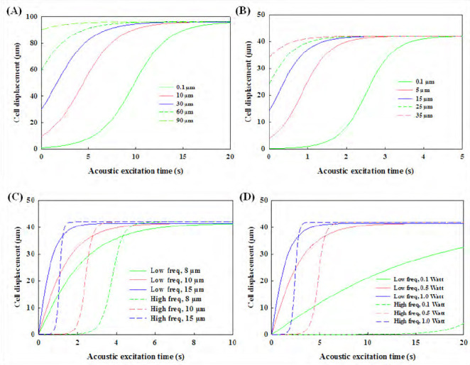
Numerical simulation of (A) 10 μm-cell trajectory excited by low- (10.4 MHz) and (B) high- (23.8 MHz) frequency standing surface acoustic wave across the cavity at the power of 0.5 W from different initial positions to the pressure nodes, and (C) the effect of thediameter of cell (8 μm, 10 μm, and 15 μm) at the excitation power of 1.0 W and (D) the effect of excitation power (0.1 W, 0.5 W, and 1.0 W) on motion of 10-μm diameter cellat thelow and high frequency with the same initial distance to the corresponding pressure node of 42 μm.
Table 2.
Correlation between acoustic parameters and cell motion by SSAW
| Parameters | Distance between pressure nodes | Cell motion velocity | Cell motion Time to reach velocity pressure node | Size of cell spheroid |
|---|---|---|---|---|
| Excitation frequency | Decrease | Increase | Decrease | Decrease |
| Power output | Constant | Increase | Decrease | Constant |
| Cell diameter | Constant | Increase | Decrease | Increase |
Figure 1.
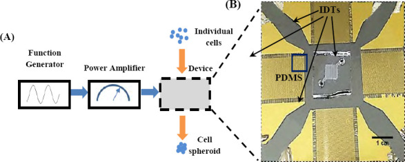
(A) Schematic diagram of experimental setup of forming cell spheroids by SSAW and (B) zoomed photo showing two pairs of interdigital transducers (IDTs) and PDMS cavity.
The trajectory motion of microparticles, either solid microspheres or cells, by the SSAW is able to be calculated and validated[46,47]. The high output power and large size of microparticles have already been found to enhance the motion velocity of microparticles[42,48]. In comparison to the solid microparticles in the similar size, cells usually have lower compressibility and density so that their motion speed is slower[49,50]. In order to reduce the time of reaching the pressure node higher output power is required, which leads to high temperature elevation of the substrate during the IDTs excitation. Another potential side effect of acoustic manipulation of cells is due to the mechanical impact. However, previous studies show that acoustic excitation at the power of about 0.87 W does not decrease the cell viability significantly, but occasionally could even enhance the cell activities[38,51]. Moreover, the initial location is one of the important factors for the cell accumulation time. The distribution of an acoustic radiation force from the standing waves is not uniform across the microchannel width[52], pointing from the anti-pressure node toward the pressure node. Both pressure nodes and anti-pressure node locations have the lowest magnitude of acoustic radiation force in the standing wave field. Thus, cells located nearby the antipressure node have the low initial acceleration, especially at the high-frequency excitation and low output power in comparison to that at the low-frequency excitation and the same output power input (see 0.1 W in Figure 2D).
It is noted that if the height of PDMS cavity is larger than the half wavelength of SSAW excitation multiple pressure nodes will be generated in the vertical direction. The magnitude and distribution of these pressure nodes in the central region of the cavity are quite uniform, but not at the edge[53]. Those cells accumulated at the middle region of pressure nodes are in the suspension and may have low possibility of attachment to the cavity. However, higher PDMS cavity may not allow the accurate measurement of the size of cell spheroids aligned vertically, but increase the production, which will be evaluated later.
3.2 Formation of Cell Spheroids by SSAW
Cell spheroids were gathered and formed from suspended individual cells under acoustic excitation, usually within 30 sec. The diameter of spheroids relies on the number of cells in the adjacent region of pressure nodes. The distance between pressure nodes in the PDMS cavity, which is the half wavelength and inverse proportional to the excitation frequency, is one of the important factors for the size of produced cell spheroids. In this experiment, both lowand high-frequency excitations could accumulate cells at the pressure nodes successfully (see Figure 3). However, the size of cell spheroids and number of accumulated cells at each pressure nodes are not exactly same. The main reason may be non-uniform cell distribution in the PDMS cavity[54] with low Reynold number, <20 (see Figure 3C). Accumulation of cells and subsequently, the formation of cell spheroids is a quite complicated phenomenon involving several factors, such as cell aggregation[55], lateral shear force[56], and culture medium (e.g., nutrients[57], growth factor[58], and waste[57]). Initial average size of cell spheroids generated by the low-frequency excitation is slightly larger than the reported value in the previous study[36] at the same cell density (2×10⁶ cells/mL), 32.8 ± 4.3 μm vs. 18.8 ± 3.0 μm. Low-frequency could gather more cells from a wide region due to its large wavelength for the generation of larger cell spheroids. Overall, it is a tradeoff between the size and accumulation speed of cell spheroids. New strategies or techniques are desired to produce large uniform cell spheroids in a short time. It is noted that low power output (e.g., 0.1 W) was applied after the cell spheroid formation for 30–90 min in order to allow sufficient ECM being secreted to hold them in place and avoid the sedimentation. No mergence of cell spheroids was found inside the PDMS cavity at the cell density used in this study. Afterwards, the spheroids are stable enough for handling and transferring.
Figure 3.
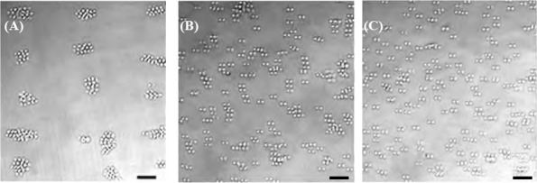
Accumulation of HepG2 cells by SSAW at the frequency of (A) 10.4 MHz, (B) 23.8 MHz, and (C) distribution of suspended cells without excitation, scale bar of 50 μm.
During the excitation, most cells initially move toward and gather with the others at the nearby pressure nodes. However, it is found that some cells locate slightly away from the pressure nodes, which may be due to attachment of cells on the surface of PDMS cavity or LiNbO3 wafer and curved wave front of SSAW inside the cavity. Cells attachment on the surface of microchannel is a common issue due to complicated surface properties[59,60]. Briefly, the attractive forces from the surface are stronger than the combination of electrostatic repulsion force and acoustic streaming forces applied to the cell[61]. Subsequently, cells could not move and follow the acoustic radiation force. When the waves travel through PDMS and fluid medium at a long distance, acoustic attenuates particularly at the high frequency is not spatially uniform because of the heterogeneous properties distribution of each medium. The diffraction waves generated from the flat IDTs lead to the slightly curved wave front, but the flat grid in the numerical simulation. In addition, cell density may also determine the magnitude of force required to tightly pack cells into spheroid. In the recent study, during of cells High cell density results in the formation of large cell were found located away from the pressure node at high cells density[36]. Furthermore, cell density is an important issue. spheroids, but also high possibility of cell attachment and cell spheroid may also be possible using SSAW at the excitation frequency of 7.4 MHz at the cell density of clogging at the outlet of cavity when collecting them. Some cell spheroids generated are about 200 μm. Such a large 30×106 cells/mL.
3.3 Growth of Cell Spheroids
After the acoustic excitation, cell spheroids were collected and cultured in the incubator for up to 7 days to monitor their growth. All formed cell spheroids grow quite well (see Figure 4). After 7 days of culture, the cell spheroids prepared by the low-frequency excitation increase from 32.8±4.3 μm to 58.7±9.2 μm (1.79 fold) while those prepared by the high-frequency excitation increase from 18.8±3.0 μm to 38.5±7.9 μm (2.05 fold) as shown in Figure 4A. In addition, the collected cell spheroids in the petri dish were not found to merge with each other during the 7-day culturing.
Figure 4.
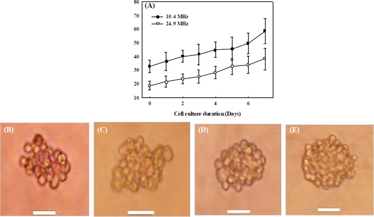
Progressive growth of the cell spheroids after the formation by SSAW (A) at 10.4 MHz (solid circle) and 23.8 MHz (hollow circle) over seven days of culture, and representative photo of cell spheroid of 10.4 MHz at (B) hour 0 (immediately after the formation), (C) hour 4, on (D) day 1, and (E) day 3 with a scale bar of 20 μm.
Overall, growth trends of cell spheroids generated by both low-frequency and high-frequencyexcitations are similar. The slope of growth seems slightly steeper after 5 days of cell culture. The cell spheroids generated by the highfrequency excitation have a slightly faster growth rate (2.05 fold in 7 days) than that by the low-frequency excitation (1.79 fold in 7 days). For large cell spheroids, the cells at the center may be less exposed to the nutrient and oxygen from the culture medium[62–64], which may slow down cell growth and lead to necrotic death[65]. After being transferred out of the PDMS cavity and collected in a culture dish, the fresh cell spheroids have clear outlines of individual cells. After 4 h, the cells in the formed spheroids start to merge with the adjacent cells. Within a day, the cell outlines in the spheroid become blurred, showing the significant cell mergence. On day 3, all cells inside the spheroid merge almost completely with the disappearance of cell outlines, especially those at the center. After that, there are no more significant changes in the morphology of the formed cell spheroids.
3.4 Cell Vability
Cell viability of HepG2 was measured on day 1, 3, 5, and 7 to investigate the influence of acoustic excitation on the formed cell spheroids. The cells undergone SSAW excitation showed a clear accumulation with adjacent cells comparing with those wihtout acosutic excitation, but without significant difference on the cell viabilities (see red fluorescent intensity in Figure 5). On day 0, the cell outlines in the cell spheroids were still clear. After 7 days of cell culture, cell spheroids became more compact and round with cell viability of 94% (see Figure 5C). Although the cell viability decreased slightly over such a period, there are always no significant differences between the cells in acoustically formed cell spheroids and suspended HepG2 the control group (p = 0.492, 0.849, 0.566, and 0.492 on day 1, 3, 5, 7, respectively, all p> 0.05, see Figure 5D). Both experimental and control group had high cell viability over 90% which represents healthy cell condition and suggests the safety of our approach. It is found that the cell viability by the high-frequency excitation was slightly lower than that by the low-frequency excitation despite without statistical difference (p< 0.05), which may be due to greater acoustic radiation force applied to the cells. The slight decrease of cell viability over time is due to the cell spheroids being cultured in non-attachable environment. If transferred to a scaffold, cell spheroids will be able to grow into a stable construct.
Figure 5.
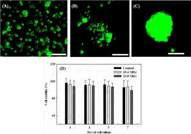
Cells stained with live/dead assay, (A) individual HepG2 cellswithout acoustic excitation in the control group, in the formed cell spheroids by the acoustic excitation on (B) day 0, (C) day 7, and (D) thepercentage of cell viability of cells with and without acoustic excitation on day 1, 3, 5, and 7.
There are two major contributions to the death of cell spheroids formed after acoustic manipulation: temperature and magnitude of acoustic radiation force applied to the cells during the acoustic excitation for approximately 30 min continuously. As the cell viability is highly sensitive to the environment temperature, a lab-built cooling plate was placed underneath the LiNbO3 substrate to release the excessive heat and control the temperature in order to reduce the thermal effects on the viability of the formed cell spheroids. The temperature of PDMS cavity was measured to be around 26 °C by an infrared thermometer (MAX IR Thermometer, Fluke, Everett, WA USA). Nevertheless, the acoustic radiation force at the pressure node for the generation of cell spheroid has a theoretical magnitude of 0. In this experiment, the cell spheroids in the diameter range of about 15 μm to 70 μm were over 90% in viability after at least 7 days of cell culture. This result is in good agreement with previous studies[36,66,67] where the cell spheroids in diameter below 100 μm could survive at a very high percentage (over 85%). However, large cell spheroids may also result in some dead cells at the center after incubation for a long time. Such limitation of spheroid size is dependent on the type of cells and the conditions of cell culture. As for hepatocyte, the mostly viable spheroid diameter could reach about 120-180 μm[66– 70]. Since oxygen is difficult to permeate through the thick cell structure, further increase in size results in a depletion of oxygen (hypoxic conditions) and causes cell necrosis in the core of large spheroids[65,71].
4. Conclusion
In this study, the device with PDMS cavity and IDTs to form cell spheroids by SSAW was developed, and its performance was evaluated. The effects of excitation frequency on the accumulation time and the size of cell spheroids immediately after the formation and growth and cell viability after culturing for up to 7 days were studied. The cell accumulation time by SSAW using the high-frequency (23.8 MHz) excitation could be reduced by ~2.5 fold compared to that using the low-frequency (10.4 MHz) frequency excitation in the simulation. Size of cell spheroids formed by the high-frequency excitation is smaller than that by the low-frequency excitation by about 43% on day 0 and 34% on day 7, respectively. The viability of HepG2 cell spheroids is over 90% up to 7 days of cell culture and similar to the control group, which illustrates no influence of acoustic manipulation and suggests the acoustically prepared cell spheroids as good candidate of bioink. In the future, this technology could be applied for various biotechnology applications (e.g., drug testing, tissue engineering, and 3D bioprinting).
Conflict of Interest
No conflict of interest was reported by all the authors.
Acknowledgments
This study was partially funded by Academic Research Fund (AcRF) Tier 1 (RG171/15), Ministry of Education, Singapore, and A*STAR-P&G Biomedical Research Council Strategic Positioning Fund (BMRC SPF, APG 2013/045A).
References
- 1.Ng W L, Wang S, Yeong W Y, et al. Skin bioprinting:Impending reality or fantasy? Trends Biotechnol. 2016;35(3):278. doi: 10.1016/j.tibtech.2016.08.009. http://dx.doi.org/10.1016/j.tibtech.2016.04.006. [DOI] [PubMed] [Google Scholar]
- 2.Ng W L, Tan J, Yeong W Y, et al. Proof-ofconcept:3D bioprinting of pigmented human skin constructs. Biofabrication. 2018:10. doi: 10.1088/1758-5090/aa9e1e. [DOI] [PubMed] [Google Scholar]
- 3.Suntornnond R, Tan E Y S, An J, et al. A highly printable and biocompatible hydrogel composite for direct printing of soft and perfusable vasculature-like structures. Sci Rep. 2017;7(1):16902. doi: 10.1038/s41598-017-17198-0. http://dx.doi.org/10.1038/s41598-017-17198-0. [DOI] [PMC free article] [PubMed] [Google Scholar]
- 4.Olubamiji A D, Izadifar Z, Si J L, et al. Modulating mechanical behaviour of 3D-printed cartilage -mimetic PCL scaffolds:Influence of molecular weight and pore geometry. Biofabrication. 2016;8(2):025020. doi: 10.1088/1758-5090/8/2/025020. http://dx.doi.org/10.1088/1758-5090/8/2/025020. [DOI] [PubMed] [Google Scholar]
- 5.Sing S L, An J, Yeong W Y, et al. Laser and electron-beam powder-bed additive manufacturing of metallic implants:A review on processes, materials and designs. J Orthop Res. 2016;34(3):369–385. doi: 10.1002/jor.23075. http://dx.doi.org/10.1002/jor.23075. [DOI] [PubMed] [Google Scholar]
- 6.Zhuang P, Sun A X, An J, et al. 3D neural tissue models:From spheroids to bioprinting. Biomaterials. 2018;154:113–133. doi: 10.1016/j.biomaterials.2017.10.002. http://dx.doi. org/ 10.1016/j.biomaterials.2017. 10.002. [DOI] [PubMed] [Google Scholar]
- 7.Lee J M, Sing S L, Tan E Y S, et al. Bioprinting in cardiovascular tissue engineering:A review. Int J Bioprint. 2016;2:27–36. http://dx.doi.org/10.18063/Ijb.2016.02.006. [Google Scholar]
- 8.Kolesky D B, Truby R L, Gladman A, et al. 3D bioprinting of vascularized, heterogeneous cell-laden tissue constructs. Adv Mater. 2014;26(19):3124–3130. doi: 10.1002/adma.201305506. http://dx.doi.org/10.1002/adma.201305506. [DOI] [PubMed] [Google Scholar]
- 9.Murphy S V, Atala A. 3D bioprinting of tissues and organs. Nat Biotechnology. 2014;32(8):773–785. doi: 10.1038/nbt.2958. http://dx.doi.org/10.1038/nbt.2958. [DOI] [PubMed] [Google Scholar]
- 10.Mehrban N, Teoh G Z, Birchall M A. 3D bioprinting for tissue engineering:Stem cells in hydrogels. Int J Bioprint. 2016;2:6–19. http://dx.doi.org/10.18063/Ijb.2016.01.006. [Google Scholar]
- 11.Ji S, Guvendiren M. Recent advances in bioink design for 3D bioprinting of tissues and organs. Front BioengBiotechnol. 2017;5:23. doi: 10.3389/fbioe.2017.00023. http://dx.doi.org/10.3389/fbioe.2017.00023. [DOI] [PMC free article] [PubMed] [Google Scholar]
- 12.Lin R Z, Chang H Y. Recent advances in threedimensional multicellular spheroid culture for biomedical research. Biotechnol J. 2008;3(9-10):1172–1184. doi: 10.1002/biot.200700228. http://dx.doi.org/10. 1002/biot.200700228. [DOI] [PubMed] [Google Scholar]
- 13.Page H, Flood P, Reynaud E G. Three-dimensional tissue cultures:Current trends and beyond. Cell Tissue Res. 2013;352(1):123–131. doi: 10.1007/s00441-012-1441-5. http://dx.doi.org/10.1007/s00441-012-1441-5. [DOI] [PubMed] [Google Scholar]
- 14.LeCluyse E L, Bullock P L, Parkinson A. Strategies for restoration and maintenance of normal hepatic structure and function in long-term cultures of rat hepatocytes. Adv Drug Deliv Rev. 1996;22(1):133–186. http://dx.doi.org/10.1016/S0169-409x(96)00418-8. [Google Scholar]
- 15.Shepherd J A, Kerlikowske K, Ma L, et al. Volume of mammographic density and risk of breast cancer. Cancer Epidemiol Biomarkers Prev. 2011;20(7):1473–1482. doi: 10.1158/1055-9965.EPI-10-1150. http://dx.doi.org/10.1158/1055-9965.EPI-10-1150. [DOI] [PMC free article] [PubMed] [Google Scholar]
- 16.Yuasa C, Tomita Y, Shono M, et al. Importance of cell aggregation for expression of liver functions and regeneration demonstrated with primary cultured hepatocytes. J Cell Physiol. 1993;156(3):522–530. doi: 10.1002/jcp.1041560311. http://dx.doi.org/10.1002/jcp.1041560311. [DOI] [PubMed] [Google Scholar]
- 17.Takabatake H, Koide N, Tsuji T. Encapsulated multicellular spheroids of rat hepatocytes produce albumin and urea in a spouted bed circulating culture system. Artif Organs. 1991;15(6):474–80. [PubMed] [Google Scholar]
- 18.Landry J, Bernier D, Ouellet C, et al. Spheroidal aggregate culture of rat liver cells:Histotypic reorganization, biomatrix deposition, and maintenance of functional activities. J Cell Biol. 1985;101(3):914–923. doi: 10.1083/jcb.101.3.914. http://dx. doi. org/https://doi.org/10.1083/jcb.101.3.914. [DOI] [PMC free article] [PubMed] [Google Scholar]
- 19.Edmondson R, Broglie J J, Adcock A F, et al. Three-dimensional cell culture systems and their applications in drug discovery and cell-based biosensors. Assay Drug Dev technol. 2014;12(4):207–218. doi: 10.1089/adt.2014.573. http://dx.doi.org/10.1089/adt.2014.573. [DOI] [PMC free article] [PubMed] [Google Scholar]
- 20.Imamura Y, Mukohara T, Shimono Y, et al. Comparison of 2D-and 3D-culture models as drug-testing platforms in breast cancer. Oncol Rep. 2015;33(4):1837–1843. doi: 10.3892/or.2015.3767. http://dx.doi.org/10.3892/or.2015.3767. [DOI] [PubMed] [Google Scholar]
- 21.Xu J S, Ma M W, Purcell W M. Characterisation of some cytotoxic endpoints using rat liver and HepG2 spheroids as in vitro models and their application in hepatotoxicity studies I. Glucose metabolism and enzyme release as cytotoxic markers. Toxicol Appl Pharmacol. 2003;189(2):112–119. doi: 10.1016/s0041-008x(03)00089-9. http://dx.doi.org/10.1016/S0041-008x(03)00089-9. [DOI] [PubMed] [Google Scholar]
- 22.Mandal B B, Kundu S C. Cell proliferation and migration in silk fibroin 3D scaffolds. Biomaterials. 2009;30(15):2956–2965. doi: 10.1016/j.biomaterials.2009.02.006. http://dx.doi.org/10.1016/j.biomate-rials.2009.02.006. [DOI] [PubMed] [Google Scholar]
- 23.Young E W, Beebe D J. Fundamentals of microfluidic cell culture in controlled microenvironments. Chem Soc Rev. 2010;39(3):1036–1048. doi: 10.1039/b909900j. http://dx.doi.org/10.1039/b909900j. [DOI] [PMC free article] [PubMed] [Google Scholar]
- 24.Norotte C, Marga F S, Niklason L E, et al. Scaffold-free vascular tissue engineering using bioprinting. Biomaterials. 2009;30(30):5910–5917. doi: 10.1016/j.biomaterials.2009.06.034. http://dx.doi.org/10.1016/j.biomaterials.2009.06.034. [DOI] [PMC free article] [PubMed] [Google Scholar]
- 25.Ozbolat I T, Yu Y. Bioprinting toward organ fabrication:Challenges and future trends. IEEE Trans Biomed Eng. 2013;60(3):691–699. doi: 10.1109/TBME.2013.2243912. http://dx.doi.org/10.1109/TBME. 2013.2243912. [DOI] [PubMed] [Google Scholar]
- 26.Lee J, Sato M, Kim H, et al. Transplantation of scaffold-free spheroids composed of synovium-derived cells and chondrocytes for the treatment of cartilage defects of the knee. Eur Cell Mater. 2011;22:275–290. doi: 10.22203/ecm.v022a21. http://dx.doi.org/https://doi.org/10.22203/ecm.v022a21. [DOI] [PubMed] [Google Scholar]
- 27.Timmins N E, Dietmair S, Nielsen L K. Hangingdrop multicellular spheroids as a model of tumour angiogenesis. Angiogenesis. 2004;7(2):97–103. doi: 10.1007/s10456-004-8911-7. http://dx.doi.org/10.1007/s10456-004-8911-7. [DOI] [PubMed] [Google Scholar]
- 28.Albrecht D R, Underhill G H, Wassermann T B, et al. Probing the role of multicellular organization in three-dimensional microenvironments. Nat Methods. 2006;3(5):369–375. doi: 10.1038/nmeth873. http://dx.doi.org/10.1038/nmeth873. [DOI] [PubMed] [Google Scholar]
- 29.Souza G R, Molina J R, Raphael R M, et al. Three-dimensional tissue culture based on magnetic cell levitation. Nat Nanotechnol. 2010;5(4):291–296. doi: 10.1038/nnano.2010.23. http://dx.doi.org/10.103 8/nnano .2010.23. [DOI] [PMC free article] [PubMed] [Google Scholar]
- 30.Ingram M, Techy G B, Saroufeem R, et al. Threedimensional growth patterns of various human tumor cell lines in simulated microgravity of a NASA bioreactor. In Vitro Cell Dev Biol Anim. 1997;33(6):459–466. doi: 10.1007/s11626-997-0064-8. http://dx.doi.org/10.1007/s11626-997-0064-8. [DOI] [PubMed] [Google Scholar]
- 31.Napolitano A P, Chai P, Dean D M, et al. Dynamics of the self-assembly of complex cellular aggregates on micromolded nonadhesive hydrogels. Tissue Eng. 2007;13(8):2087–2094. doi: 10.1089/ten.2006.0190. http://dx.doi.org/10.1089/ten.2006.0190. [DOI] [PubMed] [Google Scholar]
- 32.Semino C E, Merok J R, Crane G G, et al. Functional differentiation of hepatocyte-like spheroid structures from putative liver progenitor cells in threedimensional peptide scaffolds. Differentiation. 2003;71(4-5):262–270. doi: 10.1046/j.1432-0436.2003.7104503.x. http://dx.doi.org/10.1046/j.1432-0436.2003.7104503.x. [DOI] [PubMed] [Google Scholar]
- 33.Ng W L, Lee J M, Yeong W Y, et al. Microvalvebased bioprinting-Process, bio-inks and applications. Biomater Sci. 2017;5(4):632–647. doi: 10.1039/c6bm00861e. http://dx.doi.org/10.1039/c6bm00861e. [DOI] [PubMed] [Google Scholar]
- 34.Faulkner-Jones A, Greenhough S, King J A, et al. Development of a valve-based cell printer for the formation of human embryonic stem cell spheroid aggregates. Biofabrication. 2013;5(1):015013. doi: 10.1088/1758-5082/5/1/015013. http://dx.doi.org/10.1088/1758-5082/5/1/015013. [DOI] [PubMed] [Google Scholar]
- 35.Bazou D, Kearney R, Mansergh F, et al. Gene expression analysis of mouse embryonic stem cells following levitation in an ultrasound standing wave trap. Ultrasound Med Biol. 2011;37(2):321–330. doi: 10.1016/j.ultrasmedbio.2010.10.019. http://dx.doi.org/10.1016/j.ultrasmedbio.2010.10.019. [DOI] [PMC free article] [PubMed] [Google Scholar]
- 36.Chen K, Wu M, Guo F, et al. Rapid formation of size-controllable multicellular spheroids via 3D acoustic tweezers. Lab Chip. 2016;16(14):2636–2643. doi: 10.1039/c6lc00444j. http://dx.doi.org/10.103 9/c6lc00444j. [DOI] [PMC free article] [PubMed] [Google Scholar]
- 37.Collins D J, Morahan B, Garcia-Bustos J, et al. Two-dimensional single-cell patterning with one cell per well driven by surface acoustic waves. Nat Commun. 2015;6:8686. doi: 10.1038/ncomms9686. http://dx.doi.org/10.1038/ncomms9686. [DOI] [PMC free article] [PubMed] [Google Scholar]
- 38.Wiklund M. Acoustofuidics 12:Biocompatibility and cell viability in microfuidic acoustic resonators. Lab Chip. 2012;12(11):2018–2028. doi: 10.1039/c2lc40201g. http://dx.doi.org/10.1039/c2lc40201g. [DOI] [PubMed] [Google Scholar]
- 39.Ohlin M, Iranmanesh I, Christakou A E, et al. Temperature-controlled MPa-pressure ultrasonic cell manipulation in a microfuidic chip. Lab Chip. 2015;15(16):3341–3349. doi: 10.1039/c5lc00490j. http://dx.doi.org/10.1039/c5lc00490j. [DOI] [PubMed] [Google Scholar]
- 40.Glynne-Jones P, Hill M. Acoustofluidics 23:Acoustic manipulation combined with other force fields. Lab Chip. 2013;13(6):1003–1010. doi: 10.1039/c3lc41369a. http://dx.doi.org/10.1039/c3lc41369a. [DOI] [PubMed] [Google Scholar]
- 41.Bruus H. Acoustofluidics 7:The acoustic radiation force on small particles. Lab Chip. 2012;12(6):1014–1021. doi: 10.1039/c2lc21068a. http://dx.doi.org/10.1039/c2lc21068a. [DOI] [PubMed] [Google Scholar]
- 42.Sriphutkiat Y, Zhou Y. Particle manipulation using standing acoustic waves in the microchannel at dualfrequency excitation:Effect of power ratio. Sensor Actuat A Phys. 2017;263:521–529. http://dx.doi.org/10.1016/j.sna.2017.07.023. [Google Scholar]
- 43.Burgess A, Vigneron S, Brioudes E, et al. Loss of human Greatwall results in G2 arrest and multiple mitotic defects due to deregulation of the cyclin B-Cdc2/PP2A balance. Pro Nati Acad Sci. 2010;107(28):12564–12569. doi: 10.1073/pnas.0914191107. http://dx.doi.org/10.1073/pnas.0914191107. [DOI] [PMC free article] [PubMed] [Google Scholar]
- 44.McCloy R A, Rogers S, Caldon C E, et al. Partial inhibition of Cdk1 in G2 phase overrides the SAC and decouples mitotic events. Cell Cycle. 2014;13(9):1400–1412. doi: 10.4161/cc.28401. http://dx.doi.org/10.4161/cc.28401. [DOI] [PMC free article] [PubMed] [Google Scholar]
- 45.Cui X, Hartanto Y, Zhang H. Advances in multicellular spheroids formation. J R Soc Interface. 2017;14:20160877. doi: 10.1098/rsif.2016.0877. [DOI] [PMC free article] [PubMed] [Google Scholar]
- 46.Chen Y, Li P, Huang P H, et al. Rare cell isolation and analysis in microfluidics. Lab Chip. 2014;14(4):626–645. doi: 10.1039/c3lc90136j. http://dx.doi.org/10.1039/c3lc90136j. [DOI] [PMC free article] [PubMed] [Google Scholar]
- 47.Ding X, Peng Z, Lin S C, et al. Cell separation using tilted-angle standing surface acoustic waves. Pro Nati Acad Sci USA. 2014;111(36):12992–12997. doi: 10.1073/pnas.1413325111. http://dx.doi.org/10.1073/pnas.1413325111. [DOI] [PMC free article] [PubMed] [Google Scholar]
- 48.Sriphutkiat Y, Zhou Y. Particle accumulation in a microchannel and its reduction by a standing surface acoustic wave (SSAW) Sensors. 2017;17(1):106. doi: 10.3390/s17010106. http://dx.doi.org/10.3390/s17010106. [DOI] [PMC free article] [PubMed] [Google Scholar]
- 49.Hartono D, Liu Y, Tan P L, et al. On-chip measurements of cell compressibility via acoustic radiation. Lab Chip. 2011;11(23):4072–4080. doi: 10.1039/c1lc20687g. http://dx.doi.org/10.1039/c1 lc20687g. [DOI] [PubMed] [Google Scholar]
- 50.Nama N, Barnkob R, Mao Z, et al. Numerical study of acoustophoretic motion of particles in a PDMS microchannel driven by surface acoustic waves. Lab Chip. 2015;15(12):2700–2709. doi: 10.1039/c5lc00231a. http://dx.doi.org/10.1039/c5lc00231a. [DOI] [PMC free article] [PubMed] [Google Scholar]
- 51.Burguillos M A, Magnusson C, Nordin M, et al. Microchannel acoustophoresis does not impact survival or function of microglia, leukocytes or tumor cells. Plos One. 2013;8:e64233. doi: 10.1371/journal.pone.0064233. http://dx.doi.org/10.1371/journal.pone.0064233. [DOI] [PMC free article] [PubMed] [Google Scholar]
- 52.Ding X Y, Shi J J, Lin S C S, et al. Tunable patterning of microparticles and cells using standing surface acoustic waves. Lab Chip. 2012;12(14):2491–2497. doi: 10.1039/c2lc21021e. http://dx.doi.org/10.1039/c2lc21021e. [DOI] [PMC free article] [PubMed] [Google Scholar]
- 53.Devendran C, Albrecht T, Brenker J, et al. The importance of travelling wave components in standing surface acoustic wave (SSAW) systems. Lab Chip. 2016;16(19):3756–3766. doi: 10.1039/c6lc00798h. http://dx.doi.org/10.1039/c6lc00798h. [DOI] [PubMed] [Google Scholar]
- 54.Squires T. Microfluidics:Fluid physics at the nanoliter scale. Rev Mod Phys. 2005;7(3):977–1026. http://dx.doi.org/10.1103/RevModPhys.77.977. [Google Scholar]
- 55.Lee P J, Hung P J, Rao V M, et al. Nanoliter scale microbioreactor array for quantitative cell biology. Biotechnol Bioeng. 2006;94(1):5–14. doi: 10.1002/bit.20745. http://dx.doi.org/10.1002/bit.20745. [DOI] [PubMed] [Google Scholar]
- 56.Wang Z, Kim M C, Marquez M, et al. Highdensity microfuidic arrays for cell cytotoxicity analysis. Lab Chip. 2007;7(6):740–745. doi: 10.1039/b618734j. http://dx.doi.org/10.1039/b61∞j. [DOI] [PubMed] [Google Scholar]
- 57.Melchels F P, Barradas A M, van Blitterswijk C A, et al. Effects of the architecture of tissue engineering scaffolds on cell seeding and culturing. Acta Biomater. 2010;6(11):4208–4217. doi: 10.1016/j.actbio.2010.06.012. http://dx.doi.org/10.1016/j.actbio.2010.06.012. [DOI] [PubMed] [Google Scholar]
- 58.Lichtner R B, Schirrmacher V. Cellular distribution and biological activity of epidermal growth factor receptors in A431 cells are influenced by cell-cell contact. J Cell Physiol. 1990;144(2):303–312. doi: 10.1002/jcp.1041440217. http://dx.doi.org/10.1002/ jcp.1041440217. [DOI] [PubMed] [Google Scholar]
- 59.Henry C, Minier J P, Lefevre G. Towards a description of particulate fouling:From single particle deposition to clogging. Adv Colloid Interface Sci. 2012;185186:34–76. doi: 10.1016/j.cis.2012.10.001. http://dx.doi.org/10.1016/jxis.2012.10.001. [DOI] [PubMed] [Google Scholar]
- 60.Mustin B, Stoeber B. Single layer deposition of polystyrene particles onto planar polydimethylsiloxane substrates. Langmuir. 2016;32(1):88–101. doi: 10.1021/acs.langmuir.5b02914. http://dx.doi.org/10.1021/ acs. langmuir. 5b02914. [DOI] [PubMed] [Google Scholar]
- 61.Devendran C, Albrecht T, Brenker J, et al. The importance of travelling wave components in standing surface acoustic wave (SSAW) systems. Lab Chip. 2016;16(19):3756–3766. doi: 10.1039/c6lc00798h. http://dx.doi.org/10.1039/c6lc00798h. [DOI] [PubMed] [Google Scholar]
- 62.Drasdo D, Hohme S. A single-cell-based model of tumor growth in vitro Monolayers and spheroids. Phys Biol. 2005;2(3):133–147. doi: 10.1088/1478-3975/2/3/001. http://dx.doi.org/10.1088/1478-3975/2/3/001. [DOI] [PubMed] [Google Scholar]
- 63.Engelberg J A, Ropella G E, Hunt C A. Essential operating principles for tumor spheroid growth. BMC Syst Biol. 2008;2:110. doi: 10.1186/1752-0509-2-110. http://dx.doi.org/10.1186/1752-0509-2-110. [DOI] [PMC free article] [PubMed] [Google Scholar]
- 64.Zanoni M, Piccinini F, Arienti C, et al. 3D tumor spheroid models for in vitro therapeutic screening:A systematic approach to enhance the biological relevance of data obtained. Sci Rep. 2016;6:19103. doi: 10.1038/srep19103. http://dx.doi.org/10.1038/srep19103. [DOI] [PMC free article] [PubMed] [Google Scholar]
- 65.Anada T, Fukuda J, Sai Y, et al. An oxygenpermeable spheroid culture system for the prevention of central hypoxia and necrosis of spheroids. Biomaterials. 2012;33(33):8430–8441. doi: 10.1016/j.biomaterials.2012.08.040. http://dx.doi.org/10.1016/j.biomate-rials.2012.08.040. [DOI] [PubMed] [Google Scholar]
- 66.Glicklis R, Merchuk J C, Cohen S. Modeling mass transfer in hepatocyte spheroids via cell viability, spheroid size, and hepatocellular functions. Biotechnol Bioeng. 2004;86(6):672–680. doi: 10.1002/bit.20086. http://dx.doi.org/10.1002/bit.20086. [DOI] [PubMed] [Google Scholar]
- 67.Lee J, Cuddihy M J, Cater G M, et al. Engineering liver tissue spheroids with inverted colloidal crystal scaffolds. Biomaterials. 2009;30(27):4687–4694. doi: 10.1016/j.biomaterials.2009.05.024. http://dx.doi.org/10.1016/j .biomaterials.2009.05. 024. [DOI] [PubMed] [Google Scholar]
- 68.Curcio E, Salerno S, Barbieri G, et al. Mass transfer and metabolic reactions in hepatocyte spheroids cultured in rotating wall gas-permeable membrane system. Biomaterials. 2007;28(36):5487–5497. doi: 10.1016/j.biomaterials.2007.08.033. http://dx.doi.org/10.1016/j .biomaterials.2007.08.033. [DOI] [PubMed] [Google Scholar]
- 69.Fukuda J, Okamura K, Nakazawa K, et al. Efficacy of a polyurethane foam/spheroid artificial liver by using human hepatoblastoma cell line (Hep G2) Cell Transplant. 2003;12(1):51–58. doi: 10.3727/000000003783985151. http://dx.doi.org/10.3727/000000003783985151. [DOI] [PubMed] [Google Scholar]
- 70.Tamura T, Sakai Y, Nakazawa K. Twodimensional microarray of HepG2 spheroids using collagen/polyethylene glycol micropatterned chip. J Mater Sci Mater M. 2008;19(5):2071–2077. doi: 10.1007/s10856-007-3305-1. http://dx.doi.org/10.1007/s10856-007-3305-1. [DOI] [PubMed] [Google Scholar]
- 71.Hirschhaeuser F, Menne H, Dittfeld C, et al. Multicellular tumor spheroids:An underestimated tool is catching up again. JBiotechnol. 2010;148(1):3–15. doi: 10.1016/j.jbiotec.2010.01.012. http://dx.doi.org/10.1016/j.jbiotec.2010.01.012. [DOI] [PubMed] [Google Scholar]