Abstract
The outbreak of the corona virus disease 2019 (COVID-19) infection has spread to a large number of countries worldwide. The early diagnosis of COVID-19 is complicated by its strong transmission characteristics and no obvious symptoms in the incubation period. Due to the relatively sealed indoor environment and the existing ventilation system, the patients and doctors in the fever clinics of the major hospitals are faced with a huge risk of infection. This study aims to investigate the transport of droplet aerosols generated by both doctors and patients to seek measures to reduce the risk of infection. Taking a typical fever clinic as an object of study, two links in the actual diagnosis and treatment process are selected in this manuscript for investigation by experimental and numerical methods. The effects of different cases of coughing and talking, as well as different contact distances, on the inhalation rate of human droplet aerosols are studied. The purification capacity of the ventilation is evaluated by the analysis results of the particle diffusion track and regional concentration of the entire indoor area and breathing zones. The results show that purification of the same number of droplet aerosols and purification by ventilation work better for coughing than for talking. The best ventilation performance appeared for the case of a patient sitting and coughing (PSC), while the case of a patient lying and talking (PLT) was the worst. Corresponding measures are suggested to improve the air purification effect and reduce the risk of cross infection.
Keywords: Droplet aerosols, Ventilation, Numerical simulation, Experiment
Highlights
-
•
The transport of droplet aerosols was investigated in a typical fever clinic.
-
•
Twelve different cases were studied to analyses particle diffusion track and regional concentration.
-
•
Both experiment and numerical method were performed.
-
•
The purification capacity of the ventilation was evaluated in the entire indoor area and breathing zones.
-
•
Expected risk of infection from both patients and doctors.
1. Introduction
In recent years, the health of human beings in China has been threatened by infectious diseases, some of which could be transmitted through the air, such as SARS (2003), Avian Influenza (2004), and H1N1 (2009). In particular, a recent cluster of pneumonia was caused by COVID-19, which has spread worldwide, and more than 10 million people have been infected [1]. Many studies have shown that the spread of infectious diseases is related to the distribution of air flow indoors [[2], [3], [4], [5], [6]]. The droplets, which are produced by patients with infectious diseases with diameters less than 10 μm, are emitted through respiratory exhalation processes [7,8], such as breathing [9], coughing [10] and sneezing [11]. Droplets carrying pathogens are spread indoors under the influence of airflow and self-diffusion, causing others who remain indoors to be easily infected by inhaling airborne particles [12]. Therefore, early diagnosis and treatment are important to control the spread of disease. Although the major medical institutions have established independent fever clinics, both patients and doctors are facing a very high risk of infection because of the indoor environment. Research on the transmission characteristics of particles in fever clinics plays an important role in establishing a safe indoor environment to control the outbreak of infectious diseases.
Many studies have focused on the isolation room and operation room in hospitals as their targets. Yin et al. [13] proposed that a tracer gas (SF6) and 1- or 3-μm particles can be used to simulate contaminants breathed out by a patient, which can be validated by a computational fluid. Chen et al. [14] used a multiregion model combined with two-way flow to simulate pollutant transport in the 8A ward of Hong Kong. Knibbs et al. used CO2 as a tracer gas to measure the number of air changes, and the infection risk of patients was predicted by the infection prediction model developed by Gammaitoni and Nucci [15]. A movable superclean laminar ventilation device was added by Friberg on the basis of traditional operating room ventilation [16], and the results showed that the introduction of a superclean laminar ventilation device in a traditional ventilation operating room could reduce the number of colonies to the level of using a superclean laminar ventilation operating room. The air temperature, air velocity and volumetric flow rate entering and leaving the room were chosen by Alhamid [17] to observe the pressure distribution in the hospital operating room.
However, the clinical room is researched less often than other hospital rooms, as mentioned above. Fever clinics have the characteristics of high mobility and high risk of cross infection, especially for the health of indoor occupants during an outbreak. Reducing the risk of cross infection caused by the poor diffusion of droplet aerosols is particularly important. Therefore, in this study a numerical model is established for the fever clinic of a hospital, while a number of experiments are carried out in the actual clinic to verify the accuracy. The purification capacity of the ventilation is investigated in different cases of diagnosis and treatment links, injection modes and contact distances. The structure and layout of the fever clinic is typical in hospitals, and therefore, all the conclusions in this manuscript will be relevant to other similar fever clinics.
2. Computational method
2.1. Carrier phase
Considering the many models provided by FLUENT 16.0 for turbulence calculations, the RNG k-ε turbulence model was theoretically superior to the standard k-ε model for this application [18]. An additional production term reflecting the average strain of the main vortex was added to the ε equation, and the turbulence viscosity was modified, which improved the simulation accuracy of the vortex. Chan et al. [19] pointed out that the RNG k-ε model performs slightly better in predicting the strength of the main vortex compared with the turbulence model of the standard k-ε model, realizable k-ε model, Reynolds stress model (RSM) and large eddy simulation (LES). And the RNG k-ε model with enhanced wall treatment, was used due to its simplicity, robustness and accuracy in predicting airflow fields over solid bodies [20]. Therefore, it is more practical to use the RNG k-ε turbulence models to calculate the air field flow in our study. The series of governing equations are given as follows:
The mass equation is:
| (1) |
The momentum equation is:
| (2) |
The energy equation is:
| (3) |
The definitions of the above parameters are listed in Table 1 .
Table 1.
The definition of parameters.
| Parameters | Meanings |
|---|---|
| ui | The velocity in the xi direction |
| gi | The gravitation acceleration in the xi direction |
| p | Pressure |
| ρ | Air density |
| T | Temperature |
| μeff | Effective dynamic viscosity |
| τeff | Effective stress tensor |
| λeff | Effective thermal conductivity |
| e | Specific energy |
| Si | Momentum sink |
| Sh | Heat source |
2.2. Discrete phase
For indoor air, which is regarded as a continuum, while particles are regarded as discrete media, the Lagrangian method is used to track the propagation trajectory. By equating the particle inertia with external forces, the motion equation of the particle for the x-direction in Cartesian coordinates can be obtained as:
| (4) |
where u a and u p are the velocity of the air and particle, respectively. ρ a and ρ p are the densities of the air and particle, respectively. g x is the acceleration of gravity in the x-direction. Considering that the particles are subject to the Saffman lifting force and thermophoresis force, F x stands for an additional forces per unit mass [21]. F D(u a-u p) is the drag force per unit particle mass, and for submicron size particles (diameter = 1–10 μm), F D is set to:
| (5) |
where μ is the air dynamic viscosity and d p is the diameter of the particle. Considering the velocity slip of the wall in the mechanics of rarefied gas, C c, the Cunningham correction coefficient of the Stokes drag formula can be expressed as:
| (6) |
where λ is the mean free-path of gaseous molecules.
The turbulent diffusion of particles is simulated by a random orbit model, by which the instantaneous velocity of air u can be expressed as:
| (7) |
The average velocity of the fluid‾u is obtained by the Reynolds average Naiver-Stokes equation (RANS) using the RNG k-ε turbulence model. Based on the discrete random walk (DRW) model, the fluctuating component u' is assumed to be isotropic and to follow a Gaussian distribution, which can be obtained from Eq. (8).
| (8) |
where k is the turbulent kinetic energy and ζ is a random variable subject to a normal distribution. The integral time scale T′, the time that a particle is in turbulent motion along its trajectory, can be calculated by the turbulent diffusion of particles. The formula is
| (9) |
Because the tracking performance of fine particles is good in the flow region, the integral time scale of particles can be treated as the Lagrangian integral time scale of the air, T L. When the RNG k-ε is used, this time scale T L can be approximated as
| (10) |
Ignoring the effect of the nonvolatile content on the droplet aerosol surface vapor molar concentration, the evaporation model is simplified to a single component. The evaporation rate of droplets depends on the gradient of diffusion flux, and the velocity of the vapor entering the air term on the surface of the droplets is determined by the gradient of the vapor concentration on the surface of the droplets and air.
| (11) |
where c is the mass transfer coefficient, which is estimated by the correlation at the air-water interface [22]. C s and C ∞ are the water vapor molar concentrations at the droplet aerosol surface and in the carrier phase, respectively.
3. Numerical simulation
3.1. Physical model and computational grids
A fever clinic in northern China is selected as a research object to study the transport and distribution characteristics of droplet aerosols indoors in different cases. At present, the ventilation methods in hospitals are mainly displacement ventilation (DV) and mixed ventilation (MV). The DV mode supplies air to the lower part of the room to form an air layer with a low velocity. When the moving air encounters a heat load, it flows from the bottom to the top. The flow form is similar to that driven by piston flow. Heat and pollutants are finally discharged from the outlet on the ceiling [23,24]. In the MV mode, the air is both supplied and extracted through the diffuser on the ceiling in the fever clinic, which is widely applied [25]. A certain amount of treated air is sent into the room, which is fully mixed with the indoor turbid air, and part of the polluted air is discharged out of the room through the exhaust. However, this strategy reduces thermal comfort in the area occupied by the ventilation space and spreads contaminants and pathogens compared to DV [26]. On the basis of the actual situation in the clinic, MV was adopted in our study. According to the diagnosis and treatment situation, two main activities of the occupants are investigated. One is the patient sitting (PS) opposite the doctor across the table for corresponding consultation, and the other is the patient lying (PL) in bed and the doctor standing for relevant examination, as shown in Fig. 1 . The droplet aerosols are injected from the mouth of the occupants by coughing and talking. Except for the human body model, the physical models in the room are simplified, and the relevant parameters are given in Table 2 . (b).
Fig. 1.
Three-dimensional structure and arrangement of the fever clinic (a) PS position, (b) PL position.
Table 2.
Indoor related parameters.
| Name | Number | Size(m) | Temperature(K) | Boundary condition |
|---|---|---|---|---|
| Fever clinic | 1 | 6.53 × 3.07 × 2.8 | – | – |
| Indoor occupant | 2 | 0.3 × 0.4 × 1.7 | 304 | Trap |
| Inlet | 1 | 0.3 × 0.3 | 291 | Escape |
| Outlet | 1 | 0.5 × 0.25 | – | Escape |
| Table | 1 | 0.7 × 1.4 × 0.2 | – | Reflect |
| Cabinet | 1 | 0.5 × 0.41 × 0.65 | – | Reflect |
| Light | 2 | 0.25 × 0.25 × 0.1 | 338 | Reflect |
| Wall | – | – | – | Trap |
To ensure the accuracy of the simulation results, ICEM software is used to discretize the geometry of the model. The tetrahedron unstructured mesh is adopted to complete the whole mesh generation. For instance, considering the accuracy of the simulation calculation of microbial aerosol concentrations around the human body, the grid should be properly encrypted. The area with small velocity gradient changes is sparsely meshed because the relevant physical information changes smoothly, as shown in Fig. 2 . Three different numbers of grids are established to simulate the velocity and turbulence intensity under PS and PL position in Fig. 3 . With an increase in the grid number, the velocity and turbulence intensity cannot be substantially changed in the case of PS. The differences between 1,225,548 and 2,491,127 are obvious, whereas the differences between 2,491,127 and 3,685,419 are relatively small in the case of PL. As breathing zone of the occupants is the region of interest in our study, the grid independence verification is also conducted in Table 3 [27]. The smaller the relative error between two consecutive meshes is, the lower the maximum size of manikin/wall. For saving computing resources and time cost, 2,874,324 and 2,491,127 are employed as the number of simulation grids in the cases of PS and PL, respectively.
Fig. 2.
Mesh generation (a) PS position, (b) PL position and (c) the face of occupants.
Fig. 3.
Grid independence verification under each position (a) Velocity in PS (b) Turbulent intensity in PS(c) Velocity in PL (d) Turbulent intensity in PL.
Table 3.
Grid independence in breathing zone.
| Position | Maximum size of manikin/walls (cm) | Number of elements in zones | Relative error between two consecutive meshes (%) |
|
|---|---|---|---|---|
| Air flow | Droplet aerosols concentration | |||
| PS | 0.15/0.05 | 1,264,415 | – | – |
| 0.01/0.05 | 2,874,324 | 3.86 | 4.54 | |
| 0.01/0.025 | 3,954,315 | 1.34 | 1.76 | |
| PL | 0.15/0.05 | 1,225,548 | – | – |
| 0.01/0.05 | 2,491,127 | 4.62 | 4.81 | |
| 0.01/0.025 | 3,685,419 | 0.91 | 1.53 | |
3.2. Boundary conditions and simulation cases
For the MV applied in the fever clinic, recirculation is mainly located in the two wall corners of the room. It can be predicted that the position and intensity of the reflux area will have a substantial impact on the diffusion of particles. Considering the obstruction of the instruments and equipment to air flow, the original air distribution changes greatly, and the diffusion path of droplet aerosols will be more complex. The air flows into the room with a velocity of 1.08 m/s through the inlet, the temperature and relative humidity of which are 291 K and 40%, respectively. The airflow temperature of coughing and talking is 308 K [28], and the relative humidity is 90% [29]. Considering evaporation, the initial droplet aerosols are assumed to consist of 98.2% water and 1.8% solid volume [30]. The equilibrium diameter of the completely evaporated particle, d ep, can be expressed as [31],
| (12) |
where d 0 is the initial diameter of the droplet aerosols injected from the mouth. The initial diameter of droplet aerosols generated by coughing and talking are both set as 1 μm, 20 μm, 30 μm and 50 μm with the same number of each other. For comparative analysis, the total particles number of two injection modes are both set as 40,000 [32]. According to the implementation of the UDF, a user-defined function in Fluent software, droplet aerosols are injected from the mouth for 2 s with a velocity of 11.2 m/s when coughing and 10 s with a velocity of 2.3 m/s when talking [33]. Other boundary conditions are listed in Table 1. Several parameters are applied to analyse the air distribution and the diffusion of droplet aerosols, as shown in Table 4 .
Table 4.
Simulation cases.
| Position | Injection mode | Contact distance (m) | Injection Velocity (m/s) |
Injection duration(s) | Cases named |
|---|---|---|---|---|---|
| PS | Cough | 0.9 | 11.2 | 2 | PSC-0.9 |
| 1.1 | 11.2 | 2 | PSC-1.1 | ||
| 1.3 | 11.2 | 2 | PSC-1.3 | ||
| Talk | 0.9 | 2.3 | 10 | PST-0.9 | |
| 1.1 | 2.3 | 10 | PST-1.1 | ||
| 1.3 | 2.3 | 10 | PST-1.3 | ||
| PL | Cough | 0.9 | 11.2 | 2 | PLC-0.9 |
| 1.1 | 11.2 | 2 | PLC-1.1 | ||
| 1.3 | 11.2 | 2 | PLC-1.3 | ||
| Talk | 0.9 | 2.3 | 10 | PLT-0.9 | |
| 1.1 | 2.3 | 10 | PLT-1.1 | ||
| 1.3 | 2.3 | 10 | PLT-1.3 |
4. Experimental method
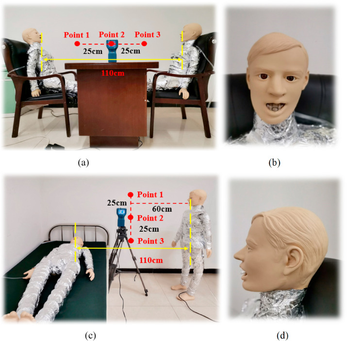
To better investigate the particle diffusion track and regional concentration, an experiment was conducted in a typical fever clinic. Two manikins were arranged in the PS or PL positions acting as the patient and doctor for droplet aerosol distribution analysis, respectively. The resistance wire around the model was evenly distributed to keep the surface temperature of the manikin at approximately 304 K. Considering the uniform heat dissipation, the surface of the manikins was covered with tin foil.
For the thorough cleaning of the ventilation, the influence of particles carried in the MV system on the experimental results can be ignored. The aerosol concentration of the test points with a size of 1 μm size should be ensured to be lower than the background concentration of 0.03 mg/m3 before each experiment [34]. 7388AGS is taken as the aerosol generation system in this experiment, which can generate particles from 0.1 to 10 μm in diameter. The solute is diisooctyl sebacate (DEHS), the density and the mass fraction of which are 914 kg/m3 and 60%, respectively. Isopropanol (C3H8O) is chosen as the solvent. The droplet aerosols are injected from the hose in the mouth of the manikins with velocities of 11.2 ± 0.1 m/s and 2.3 ± 0.1 m/s, respectively. Fig. 4 shows the size distribution of the droplet aerosols emitted from the mouth of the manikin. TSI 8220, ranging the particle diameter from 0.3 to 10 μm, is applied as an aerosol monitor. The droplet aerosol concentrations at three test points between the manikins are collected from 1 s to 300 s. Other conditions, such as the temperature and relative humidity of the air flow, are 291 ± 1 K and 40 ± 1%, respectively, which are all similar to the simulation cases. The experimental picture is shown in Fig. 5 .
Fig. 4.
Size distribution of the droplet aerosols.
Fig. 5.
Field experimental picture. (a) PS positon, (b) front view of manikin face, (c) PL position, and (d) side view of manikin face.
5. Results and discussion
5.1. Validation of the numerical model
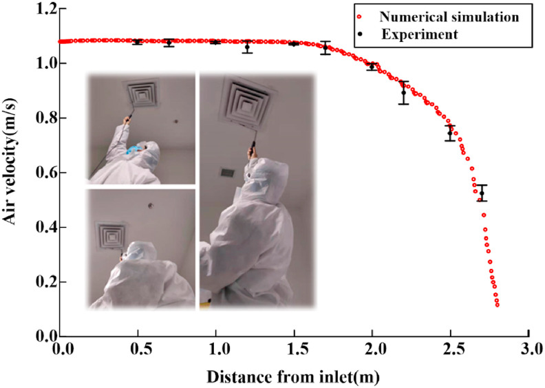
Flow field verification can ensure the accuracy of the numerical simulation results of the continuous phase fluid. As shown in Fig. 6 , the air velocities at ten points (0.5 m, 0.7 m, 1.0 m, 1.2 m, 1.5 m, 1.7 m, 2.0 m, 2.2 m, 2.5 m and 2.7 m away from the air inlet) are measured using a hot wire anemometer in this manuscript. The simulated air velocities at all the points are basically consistent with the experimental data. The difference between the simulation and actual results is extremely small, which can ensure the reliability of the boundary condition setting.
Fig. 6.
Air velocity of experiment and simulation results.
It is more obvious to compare experimental data with numerical results with a dimensionless concentration, C(%), which can be expressed as
| (13) |
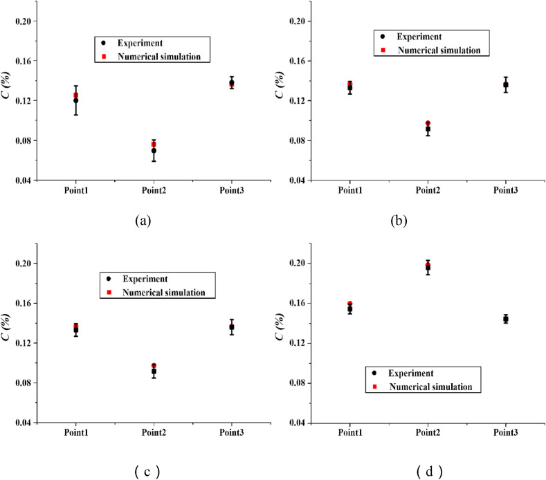
where C(x,t) is the average concentration of droplet aerosols at the test point and C 0 is the initial concentration of droplet aerosols injected from the mouth. Four cases with a distance of 1.1 m are selected to display the dimensionless concentration of the experiment and simulation results in Fig. 7 . The maximum differences of C(%) are 0.006%, 0.006%, 0.017% and 0.005%, indicating that the numerical predictions are highly consistent with the experimental data, which demonstrates the validity the of subsequent simulations.
Fig. 7.
Dimensionless concentration of experiment and simulation results. (a) PSC-1.1, (b) PST-1.1, (c) PLC-1.1 and (d) PLT-1.1.
5.2. The transport of droplet aerosols in the entire indoor area
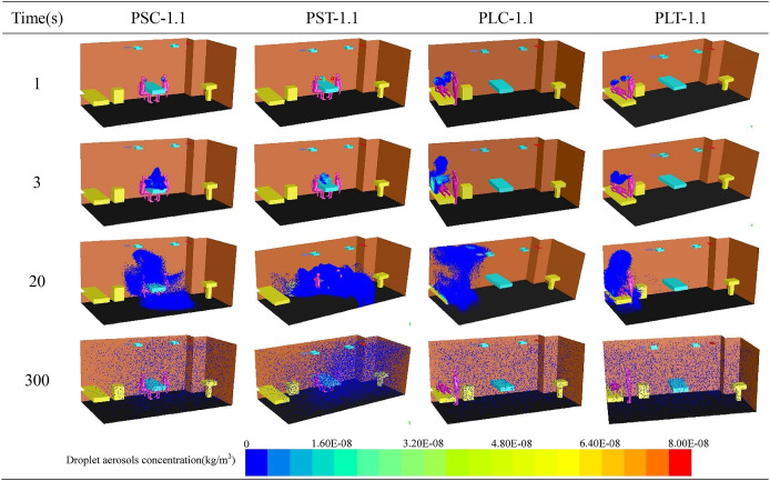
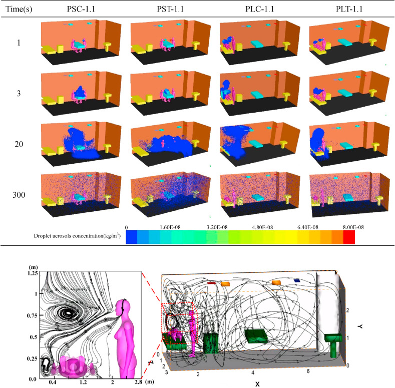
Four different cases are chosen from twelve cases to show the distribution of droplet aerosols with time and space as shown in Table 5 . It can be seen from the table that the change trend of the droplet aerosol concentration with time changes from dense to sparse and gradually spreads to the whole fever clinic. When the patient and the doctor maintain a face-to-face sitting position, the droplet aerosols are concentrated on the faces of the two people at the beginning. The droplet aerosols are gradually gathered above the head and the blank area beside the table by MV and quickly discharge from the breathing zone of the occupants with time. However, due to the poor ventilation between the occupants in Fig. 8 , the droplet aerosols are concentrated around the patient and the upper area when the patient is lying and the doctor is in a standing position. Compared to the PS case, droplet aerosols are difficult to discharge with airflow, and lying patients are extremely susceptible to droplet aerosols.
Table 5.
Droplet aerosols diffusion with time under different cases.
Fig. 8.
The streamline of numerical simulation of entire indoor area and enlarged view of breathing zone. (c) (d).
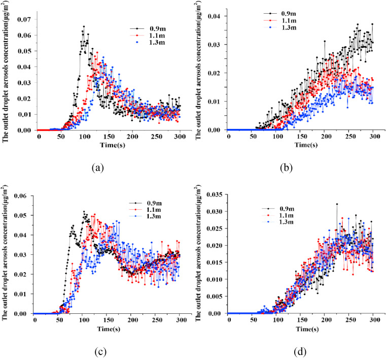
Fig. 9 shows the droplet aerosols concentration at the outlet changes with time at different contact distances. In all the cases, droplet aerosols appeared at the outlet, the concentration of which fluctuated with increasing time from 50 s. Fig. 9(a) shows that the droplet aerosols concentration at the outlet reaching the maximum is delayed from 98 s to 139 s as the distance gradually increases. The peak value is reduced from 6.5 E−2 μg/m2 to 4.6 E−2 μg/m2, the variation law of which is similar to that shown in Fig. 9(c). The droplet aerosols concentration of the outlet at the three different distances of PSC reaches a stable level of approximately 1 E−2 μg/m2 in the following time. The droplet aerosols concentration of PLC did not remain stable, however, it increased slowly from 2 E−2 μg/m2 after 200 s, which is twice as high as that of PSC in the same period.
Fig. 9.
The variation tendency of droplet aerosols concentration with time at the outlet. (a) PSC, (b) PST, (c) PLC and (d) PLT.
In Fig. 9(b), the time when the droplet aerosols appear at the outlet of the fever clinic is also correspondingly delayed. When the distances are 0.9 m, 1.1 m and 1.3 m, the droplet aerosols occurrence times at the outlet are 52 s, 75 s and 100 s, respectively. When the distance increases from 0.9 m to 1.1 m, the droplet aerosols concentration at the outlet decreases from 3 E−2 μg/m2 to 1.7 E−2 μg/m2, the purification effect of which is significant. However, the improvement effect is not obvious as the distance increases to 1.3 m. Compared to the PST, different distances have little effect on the droplet aerosols concentration, the change in which is relatively consistent with the PLT in Fig. 9(d).
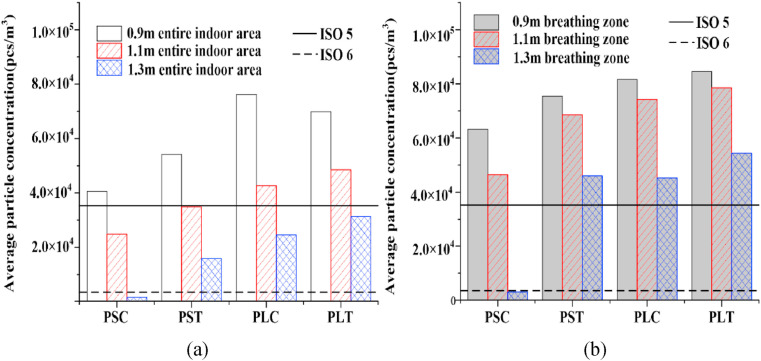
As mentioned by He et al. [35], The relative position of the occupants in the indoor environment plays a key role in the risk of cross infection. Drawing into the standards of ISO5 and ISO6 in the code for the design of clean room (GB50073-2013) [36], a comparison of the average droplet aerosols concentrations in the entire indoor area at different distances is given in Fig. 10 (a). In all cases, the droplet aerosols concentration in the PL position is generally higher than that in the PS position. With increasing distance, the concentration decreases, the similar result is also obtained by Kang et al. [37]. When the distance is between 1.1 m and 1.3 m, the droplet aerosol concentrations in the PS position are all lower than the maximum concentration (3.52 × 10³ pcs/m3) required by ISO6. The optimum value of the droplet aerosols concentration is determined by the case of PSC-1.3, which is lower than the standard of ISO5, 3.52 × 10⁴ pcs/m3. This is caused by the layout of indoor facilities where the bed is placed in the corner of the fever clinic. As a result of poor air circulation, droplet aerosols cannot be effectively discharged. Therefore, the purification effect of MV for PS is better than that for PL in the entire indoor area. The patial relationship between the ventilation system and the occupants greatly affects the transport of droplet aerosols [38].
Fig. 10.
Comparison of droplet aerosols average concentration at different contact distances. (a) entire indoor area (b) breathing zone.
5.3. The transport of droplet aerosols in the breathing zone
The distribution and diffusion trend of droplet aerosols in the breathing zone plays a key role in ventilation evaluation. The average droplet aerosol concentration of the breathing zone is displayed in Fig. 10(b). Except for the case of PSC, the trend of the changes in the droplet aerosols concentration with distance is basically the same. The best ventilation performance in the breathing zone is presented in the case of PSC-1.3, the droplet aerosols concentration of which reaches the minimum of 1.59 × 10³ pcs/m3, which is lower than the ISO6 standard. The droplet aerosol concentrations of PST at three distances are higher than those of the other corresponding cases, resulting in the eddy current region in Fig. 8. The maximum concentration in the breathing zone is presented in the case of PLT-0.9, the value of which is 8.46 × 10⁴ pcs/m3, which is more than twice that of ISO5.
Considering that the average concentration of droplet aerosols in the entire indoor area is generally lower than that in the breathing zone in Fig. 10, indoor occupants are suggested to avoid staying in the breathing zone for a long time. In the same position, the purification effect of ventilation on the droplet aerosols produced by coughing is better than that of the talking condition. For the same number of droplet aerosols, purification by ventilation works better for coughing than for talking.
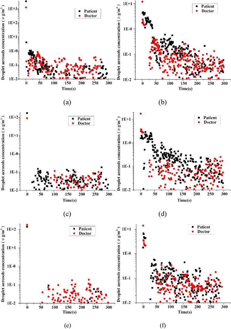
The cases of PSC and PLT are selected to investigate the change trend of the droplet aerosols concentrations in the breathing zone in Fig. 11 . The droplet aerosols concentration in the breathing zone decreases gradually with time and eventually remains stable in PSC while still has a downward trend in PLT. At all distances of PLT, droplet aerosols existed in the breathing zone of the patient and doctor during the entire simulation time. The duration of droplet aerosols is phased with increasing distance in the case of PSC. When the distance is 0.9 m, the duration is 300 s. The influence time of the patient is delayed after 50 s, while that of the doctor is delayed after 80 s at a distance of 1.1 m. The impacts of droplet aerosols are both presented after 50 s, and even the main effect on the patient is after 225 s in the case of PSC-1.3.
Fig. 11.
Comparison of the changes of concentration in breathing zone with time (a) PSC-0.9, (b) PLT-0.9, (c) PSC-1.1, (d) PLT-1.1, (e) PSC-1.3 and (f) PLT-1.3.
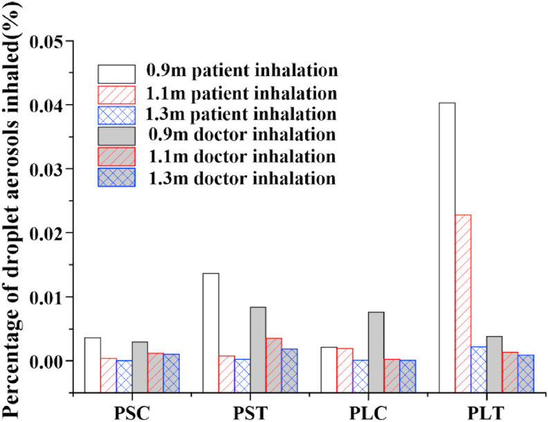
Overall, the percentage of droplet aerosols inhaled by doctors is smaller than that inhaled by patients, and the risk of infection by doctors is lower in Fig. 12 . Considering the low inhalation percentage of patients and doctors, the ventilation performance for the condition PSC is the best. The highest percentage of droplet aerosols inhaled by the patient is presented in the case of PLT, which is the worst compared with all the other cases. In this case, the patient and doctor are both placed in the corner of the entire room, where it is difficult to discharge droplet aerosols from this area. In addition, due to the influence of gravity and the injection angle, the droplet aerosol trajectory of the doctor will fall into the patient's breathing zone in the form of a parabola, which is easily inhaled by the patient. It is also the reason that the percentage of droplet aerosols inhaled by the patient drops dramatically with increasing distance. When the distance between the two is 1.3 m, the percentage of droplet aerosols is only 0.002%. Therefore, a safe distance of no less than 1.5 m should be kept to avoid the cross infection of occupants in a typical fever clinic.
Fig. 12.
Comparison of percentage of droplet aerosols inhaled.
6. Conclusion
For the overload capacity of epidemic situation caused by COVID-19, patients and doctors are at great risk of cross infection due to the layout of fever clinics and ventilation in existing hospitals. Taking a fever clinic as an object, twelve cases, including different diagnoses and treatment links, different injection modes and different contact distances, were analysed by numerical simulation after experimental verification. For vortices appearing at the corner of the room, the purification effect of the case of PL is worse than that of PS in the entire indoor area. Considering the injection angle of the droplet aerosols, the ventilation performance for the PSC condition is the best, while PLT is the worst in the breathing zone. The farther the distance between the occupants is, the better the pollutant removal effect and the lower the risk of infection. For the same number of droplet aerosols, purification by ventilation works better for coughing than for talking. On the premise of fully considering operability under epidemic conditions, the following improvement measures are proposed for the existing rooms. Moving the bed to the open space beside the table next to the middle of the wall. Increasing the contact distance, no less than 1.5 m should be considered as the safe distance. Wearing protective devices will also be the effective methods. All these measures can improve the purification effect of the existing ventilation and reduce the risk of infection.
Future studies should be focused on optimizing the layout of the fever clinic and improving the air distribution for efficient removing of droplet aerosols. Meanwhile, the occupants would likely cough to the sides or to the ground, or cover his/her mouth with hands or an arm. All these dynamic characteristics should be considered in the further investigation.
Declaration of competing interest
The authors declare that they have no known competing financial interests or personal relationships that could have appeared to influence the work reported in this paper.
Nomenclature
- COVID-19
Corona Virus Disease 2019
- CFD
Computational fluid dynamics
- RSM
Reynolds stress model
- LES
Large Eddy Simulation
- RANS
Reynolds average Naiver-Stokes equation
- DRW
Discrete Random Walk
- MV
mixed ventilation
- DV
displacement ventilation
- PS
patient sitting
- PL
patient lying
- PSC
patient sitting and coughing
- PST
patient sitting and talking
- PLC
patient lying and coughing
- PLT
patient lying and talking
- U
velocity in some direction [m/s]
- G
gravitation acceleration in some direction [m/s2]
- xi
space coordinate component
- p
pressure [Pa]
- T
temperature [K]
- E
specific energy [J/kg]
- Si
momentum sink [N/s2]
- Sh
heat source [N/s2]
- ua
velocity of the air [m/s]
- up
velocity of the particle [m/s]
- Fx
additional forces per unit mass [N]
- FD
sub crown size particles [μm]
- dp
diameter of the particle [μm]
- Cc
Cunningham correction coefficient of Stokes drag formula
- ‾u
average velocity of the fluid [m/s]
- U
air the instantaneous velocity [m/s]
- u'
fluctuating component [m/s]
- k
turbulent kinetic energy [m2/s2]
- T′
integral time scale [s]
- TL
Lagrangian integral time scale of the air [s]
- C
mass transfer coefficient
- Cs
the molar concentration of at droplet aerosols surface
- C∞
molar concentration of water vapor in the carrier phase
- dep
the equilibrium diameter of the completely evaporated particle[μm]
- d0
the initial diameter of droplet aerosols[μm]
- C(%)
dimensionless concentration
- C(x,t)
the average concentration of droplet aerosol at test point
- C0
the initial concentration of droplet aerosol
Greek symbols
- Ρ
density [kg·m−3]
- μeff
dynamic viscosity [Pa·s]
- τeff
stress tensor
- λeff
thermal conductivity [W·m−2·K−1]
- λ
mean free-path of gaseous molecules
- ζ
random variable subject to normal distribution
Subscripts
- Eff
the effective parameter
- i
component value, equates 1, 2 and 3
- a
air
- p
particle
References
- 1.Wang F.S., Zhang C. What to do next to control the 2019-nCoV epidemic? [J] Lancet. 2020;395(10222):391–393. doi: 10.1016/S0140-6736(20)30300-7. [DOI] [PMC free article] [PubMed] [Google Scholar]
- 2.Yu I.T.S., Li Y., Wong T.W. Evidence of airborne transmission of the severe acute respiratory syndrome virus[J] N. Engl. J. Med. 2004;350(17):1731–1739. doi: 10.1056/NEJMoa032867. [DOI] [PubMed] [Google Scholar]
- 3.Li Y., Leung G.M., Tang J.W. Role of ventilation in airborne transmission of infectious agents in the built environment-a multidisciplinary systematic review[J] Indoor Air. 2007;17:2–18. doi: 10.1111/j.1600-0668.2006.00445.x. [DOI] [PubMed] [Google Scholar]
- 4.Gao R., Li A. Dust deposition in ventilation and air-conditioning duct bend flows[J] Energy Convers. Manag. 2012;55(none):49–59. doi: 10.1016/j.enconman.2011.10.018. [DOI] [Google Scholar]
- 5.Zhao B., Zhang Z., Li X. Numerical study of the transport of droplets or particles generated by respiratory system indoors[J] Build. Environ. 2005;40(8):1032–1039. doi: 10.1016/j.buildenv.2004.09.018. [DOI] [PMC free article] [PubMed] [Google Scholar]
- 6.Tung Y., Shih Y., Hu S. Numerical study on the dispersion of airborne contaminants from an isolation room in the case of door opening[J] Appl. Therm. Eng. 2009;29:1544–1551. doi: 10.1016/j.applthermaleng.2008.07.009. [DOI] [PMC free article] [PubMed] [Google Scholar]
- 7.Feng G., Bi Y., Zhang Y. Study on the motion law of aerosols produced by human respiration under the action of thermal plume of different intensities[J] Sustainable Cities and Society. 2019;54:101935. doi: 10.1016/j.scs.2019.101935. [DOI] [PMC free article] [PubMed] [Google Scholar]
- 8.Milton D.K., Fabian M.P., Cowling B.J., Grantham M.L. Influenza virus aerosols in human exhaled breath: particle size, cultivability, and effect of surgical masks. PLoS Pathog. 2013;9 doi: 10.1371/journal.ppat.1003205. [DOI] [PMC free article] [PubMed] [Google Scholar]
- 9.Berlanga F.A., Olmedo I., Ruiz M. Experimental analysis of the air velocity and contaminant dispersion of human exhalation flows[J] Indoor Air. 2016:1–13. doi: 10.1111/ina.12357. [DOI] [PubMed] [Google Scholar]
- 10.Gupta J.K., Lin C.H., Chen Q. Flow dynamics and characterization of a cough[J] Indoor Air. 2009;19:517–525. doi: 10.1111/j.1600-0668.2009.00619.x. [DOI] [PubMed] [Google Scholar]
- 11.Tang J., Nicolle A., Klettner C., Pantelic J., Wang L. Airflow dynamics of human jets: sneezing and breathing-potential sources of infectious aerosols. PloS One. 2013;8 doi: 10.1371/journal.pone.0059970. [DOI] [PMC free article] [PubMed] [Google Scholar]
- 12.Zhao B., Zhang Z., Li X. Numerical study of the transport of droplets or particles generated by respiratory system indoors[J] Build. Environ. 2005;40(8):1032–1039. doi: 10.1016/j.buildenv.2004.09.018. [DOI] [PMC free article] [PubMed] [Google Scholar]
- 13.Yin Y., Xu W., Gupta J. Experimental study on displacement and mixing ventilation systems for a patient ward[J] HVAC R Res. 2009;15(6):1175–1191. doi: 10.1080/10789669.2009.10390885. [DOI] [Google Scholar]
- 14.Chen C., Zhao B., Yang X.D., Li Y.G. Role of two-way airflow owing to temperature difference in severe acute respiratory syndrome transmission: revisiting the largest nosocomial severe acute respiratory syndrome outbreak in Hong Kong[J] J. R. Soc. Interface. 2011;8(58):699–710. doi: 10.1098/rsif.2010.0486. [DOI] [PMC free article] [PubMed] [Google Scholar]
- 15.Knibbs L.D., Morawska L., Bell S.C. Room ventilation and the risk of airborne infection transmission in 3 health care settings within a large teaching hospital[J] Am. J. Infect. Contr. 2011;39(10):866–872. doi: 10.1016/j.ajic.2011.02.014. [DOI] [PMC free article] [PubMed] [Google Scholar]
- 16.Friberg S., Ardnor B., Lundholm R. The addition of a mobile ultra-clean exponential laminar airflow screen to conventional operating room ventilation reduces bacterial contamination to operating box levels[J] J. Hosp. Infect. 2003;55(2):92–97. doi: 10.1016/S0195-6701(03)00143-9. [DOI] [PubMed] [Google Scholar]
- 17.Alhamid M.I., Budihardjo Rahmat. Performance analysis of air conditioning system and airflow simulation in an operating theater[C]//biomedical engineerings recent progress in biomaterials, drugs development, & medical devices. International Symposium of Biomedical Engineering. 2018 doi: 10.1063/1.5023991. [DOI] [Google Scholar]
- 18.Ansys Fluent 16.0, Theory Guide. Ansys Inc.; 2015. https://www.ansys.com [Google Scholar]
- 19.Chan T.L., Dong G., Leung C.W. Validation of a two-dimensional pollutant dispersion model in an isolated street canyon[J] Atmos. Environ. 2002;36(5):861–872. doi: 10.1016/S1352-2310(01)00490-3. [DOI] [Google Scholar]
- 20.Al Assaad D., Ghali K., Ghaddar N. Particles dispersion due to human prostration cycle and ventilation system in a prayer room[J] Build. Environ. 2019;150(MAR.):44–59. doi: 10.1016/j.buildenv.2019.01.005. [DOI] [Google Scholar]
- 21.Li Amy, Ahmadi Goodarz. Dispersion and deposition of spherical particles from point sources in a turbulent channel flow[J] Aerosol Sci. Technol. 1992;16(4):209–226. doi: 10.1080/02786829208959550. [DOI] [Google Scholar]
- 22.Ranz W.E., Marshall W.R. Evaporation from drops. Chem. Eng. Prog. 1952;48(3):141–146. [Google Scholar]
- 23.Mateus N.M., Da G.C. Simplified modeling of displacement ventilation systems with chilled ceilings. Energy Build. 2015;108:44–54. doi: 10.1016/j.enbuild.2015.08.054. [DOI] [Google Scholar]
- 24.Mundt E. Contamination distribution in displacement ventilation-influence of disturbances. Build. Environ. 1994;29:311–317. doi: 10.1016/0360-1323(94)90028-0. [DOI] [Google Scholar]
- 25.Ye X., Zhu H., Kang Y., Zhong K. Heating energy consumption of impinging jet ventilation and mixing ventilation in large-height spaces: a comparison study[J] Energy Build. 2016;130:697–708. doi: 10.1016/j.enbuild.2016.08.055. [DOI] [Google Scholar]
- 26.Behne M. Indoor air quality in rooms with cooled ceilings. Mixing ventilation or rather displacement ventilation? Energy Build. 1999;30:155–166. doi: 10.1016/S0378-7788(98)00083-8. [DOI] [Google Scholar]
- 27.Al Assaad D., Ghali K., Ghaddar N. Effectiveness of intermittent personalized ventilation assisting a chilled ceiling for enhanced thermal comfort and acceptable indoor air quality[J] Build. Environ. 2018;144(OCT):9–22. doi: 10.1016/j.buildenv.2018.08.005. [DOI] [Google Scholar]
- 28.Gao N., Niu J., Morawska L. Distribution of respiratory droplets in enclosed environments under different air distribution methods[J] Building Simulation. 2008;1(4):326–335. doi: 10.1007/s12273-008-8328-0. [DOI] [Google Scholar]
- 29.Morawska L., Johnson G.R., Ristovski Z.D., Hargreaves M., Mengersen K., Corbett S. Size distribution and sites of origin of droplets expelled from the human respiratory tract during expiratory activities[J] J. Aerosol Sci. 2009;40(3):256–269. doi: 10.1016/j.jaerosci.2008.11.002. [DOI] [PMC free article] [PubMed] [Google Scholar]
- 30.Graham D.I., James P.W. Turbulent dispersion of particles using eddy interaction models[J] Int. J. Multiphas. Flow. 1996;22(1):157–175. doi: 10.1016/0301-9322(95)00061-5. [DOI] [Google Scholar]
- 31.Chao C.Y.H., Wan M.P. A study of the dispersion of expiratory aerosols in unidirectional downward and ceiling-return type airflows using a multiphase approach[J] Indoor Air. 2006;16(4):296–312. doi: 10.1111/j.1600-0668.2006.00426.x. [DOI] [PubMed] [Google Scholar]
- 32.Lindsley W.G., Pearce T.A., Hudnall J.B. Quantity and size distribution of cough-generated aerosol particles produced by Influenza patients during and after illness[J] J. Occup. Environ. Hyg. 2012;9(7):443–449. doi: 10.1080/15459624.2012.684582. [DOI] [PMC free article] [PubMed] [Google Scholar]
- 33.Chao C.Y.H., Wan M.P., Morawska L. Characterization of expiration air jets and droplet size distributions immediately at the mouth opening[J] J. Aerosol. 2009;40(2):122–133. doi: 10.1016/j.jaerosci.2008.10.003. [DOI] [PMC free article] [PubMed] [Google Scholar]
- 34.Zhang Y., Feng G., Bi Y. Distribution of droplet aerosols generated by mouth coughing and nose breathing in an air-conditioned room[J] Sustainable Cities and Society. 2019;51:101721. doi: 10.1016/j.scs.2019.101721. [DOI] [Google Scholar]
- 35.He Qibin, Niu Jianlei, Gao Naiping, Zhu Tong, Wu Jiazheng. CFD study of exhaled droplet transmission between occupants under different ventilation strategies in a typical office room. Build. Environ. 2010;46:397–408. doi: 10.1016/j.buildenv.2010.08.003. [DOI] [PMC free article] [PubMed] [Google Scholar]
- 36.Ministry of Industry and Information Technology of the People's Republic of China. Code for Design of Clean Workshop. China Planning Press; 2013. http://www.jianbiaoku.com/webarbs/book/384/899208.shtml [M] [Google Scholar]
- 37.Kang Z.Q., Zhang Y.X., Fan H.B., Feng G.H. ISHVAC-COBEE 2015); Tianjin: 2015. Numerical Simulation of Coughed Droplets in the Air-Conditioning Room [C]. The 9th International Sympsium on Heating, Vetilation and Air Conditioning and the 3rd International Conference on Building Energy and Environment; p. 209. [DOI] [Google Scholar]
- 38.Zhu S., Kato S., Yang J.H. Study on transport characteristics of saliva droplets produced by coughing in a calm indoor environment[J] Build. Environ. 2006;41(12):1691–1702. doi: 10.1016/j.buildenv.2005.06.024. [DOI] [Google Scholar]


