

Summary
The respiratory and intestinal tracts are exposed to physical and biological hazards accompanying the intake of air and food. Likewise, the vasculature is threatened by inflammation and trauma. Mucin glycoproteins and the related von Willebrand factor guard the vulnerable cell layers in these diverse systems. Colon mucins additionally house and feed the gut microbiome. Here, we present an integrated structural analysis of the intestinal mucin MUC2. Our findings reveal the shared mechanism by which complex macromolecules responsible for blood clotting, mucociliary clearance, and the intestinal mucosal barrier form protective polymers and hydrogels. Specifically, cryo-electron microscopy and crystal structures show how disulfide-rich bridges and pH-tunable interfaces control successive assembly steps in the endoplasmic reticulum and Golgi apparatus. Remarkably, a densely O-glycosylated mucin domain performs an organizational role in MUC2. The mucin assembly mechanism and its adaptation for hemostasis provide the foundation for rational manipulation of barrier function and coagulation.
Keywords: mucins, mucus, disulfide bonds, von Willebrand factor, quaternary structure, O-glycosylation, cryo-EM, X-ray crystallography, polymer, protein assembly
Graphical Abstract
Highlights
-
•
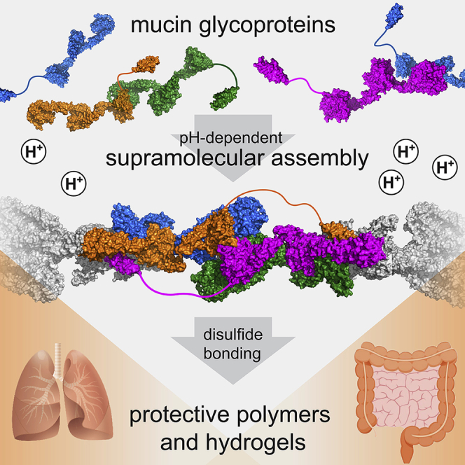
Mucin glycoprotein supramolecular assembly at Golgi pH promotes polymer formation
-
•
O-glycosylated regions help orchestrate mucin assembly
-
•
CysD domains have a novel fold, calcium binding motifs, and a role in mucin assembly
-
•
Mucins and von Willebrand factor share a mechanism to form linear polymers
Javitt et al. describe molecularly how mucin glycoproteins and von Willebrand factor—complex macromolecules responsible for mucociliary clearance in the lung, the intestinal mucosal barrier, and blood clotting—use a shared mechanism to form polymers and hydrogels that protect the respiratory tract, intestinal tract, and vasculature.
Introduction
In the respiratory tract, secreted mucin glycoproteins are swept along the airway surface by the beating of cilia to flush out entrapped pathogens and particulate matter (Bustamante-Marin and Ostrowski, 2017). In the intestines, mucins support the gut microbiome (Johansson et al., 2011) while keeping intestinal contents at a safe distance from the epithelium and lubricating the mucosal surface (Figure 1A). To carry out these essential functions, gel-forming mucins assemble into extended disulfide-linked architectures. The respiratory mucins form bundles of linear covalent polymers (Thornton et al., 2018), and it was proposed that the intestinal mucins form a stacked hexagonal network (Ambort et al., 2012; Nilsson et al., 2014). The non-mucin glycoprotein von Willebrand factor (VWF), produced by endothelial cells and platelets, evolved by exploiting aspects of the mucin disulfide-mediated assembly mechanism to generate shear-sensitive polymers involved in hemostasis and thrombosis (Springer, 2014) (Figure 1A).
Figure 1.

Mucins and von Willebrand Factor
(A) Functions of mucins and VWF. Green rods, bacteria of the intestinal microbiome; brown hexagons, particulate matter in the respiratory tract; green cells associated with VWF, activated platelets.
(B) Flexible molecules that associate by their termini could form either defined oligomerization states, e.g., a “closed” dimer (top), or polymers (bottom). Relevant domains are displayed and color-coded as in (C). Disulfide bonds are illustrated as paired yellow balls.
(C) Domain organization of gel-forming mucins and VWF (see also Figures S1, S2, and S3). Protein lengths in amino acids are shown to the right. The MUC2 head is expanded to show all modules (Nilsson et al., 2014). “Cradle” and “bridge” refer to structural features revealed in this work. Positions of cysteines forming intersubunit disulfides during mucin assembly are indicated by yellow balls. The CTCK domain mediates disulfide-linked tail dimerization (Zhou and Springer, 2014). Human MUC2 has a PTS stretch of more than 2,300 amino acids with 60% threonine and 20% proline content.
Mucin and VWF assembly begins with the formation of disulfide-bonded dimers linked by their carboxy termini (“tails”) in the endoplasmic reticulum, followed by higher-order disulfide-mediated multimerization via the amino termini (“heads”) later in the secretory pathway (Perez-Vilar et al., 1996, 1998; Wagner and Marder, 1984). An unresolved aspect of multimer assembly is the mechanism by which molecules with a tendency to associate at each end form polymers or networks rather than closed dimers (Figure 1B). This problem has long been appreciated for VWF (Huang et al., 2008; Zhou et al., 2011). Furthermore, it is not obvious, considering their extensive homology (Figures 1C, S1, and S2), how the respiratory and intestinal mucins could form different multimeric structures (linear polymers versus hexagonal networks). The current study investigates intestinal mucin assembly and identifies principles shared with respiratory mucins and VWF. Illuminating mucin assembly is valuable because it provides a basis for addressing mucin-related diseases such as cystic fibrosis and colitis (Hansson, 2019), for manipulating the environment of the gut microbiome (Gouyer et al., 2015; Schroeder, 2019), for augmenting the primary host barrier against infections (Lindén et al., 2008; Desai et al., 2016), and for enhancing chemotherapy (Rao et al., 2017). In addition, knowledge of the mechanisms for formation of natural extracellular glycoprotein networks may guide the design of artificial scaffolds for tissue engineering and other biotechnological applications.
Figure S1.

Amino Acid Sequences of Gel-Forming Mucins, Related to Figures 1 and 3
T-coffee (Notredame et al., 2000) was used to align the amino-terminal regions of human Mucin 2 (MUC2), Mucin 5B (MUC5B), Mucin 5AC (MUC5AC), Mucin 6 (MUC6) and Mucin 19 (MUC19). Assembly and module designations are given in bars above the alignment. Predicted signal peptides (Petersen et al., 2011) are underlined. Cysteines (except in the signal peptides) are highlighted in yellow and numbered according to the MUC2 precursor sequence (Uniprot Q02817). In green are calcium-binding residues in VWD2, and in blue are charged/polar amino acids involved in the quaternary structural interaction shown in Figure 3E.
Figure S2.

Amino Acid Sequences of Gel-Forming Mucins, Related to Figures 1, 3, and 4
Continuation of the alignment presented in Figure S1. In green are calcium-binding residues in VWD3, and in blue are charged/polar amino acids involved in the quaternary structural interaction shown in Figure 3E. In orange are conserved charged/polar residues at the interface between D3 assemblies in the bead center, some of which are shown in Figure 4D.
Studying large and flexible glycoproteins is challenging. Various models for the mucin and VWF head regions have been put forth based on low-resolution structural data (Huang et al., 2008; Ambort et al., 2012; Nilsson et al., 2014; Ridley et al., 2014; Trillo-Muyo et al., 2018), but a consistent picture for their arrangement and multimerization had yet to emerge. An X-ray crystal structure of a monomeric version of the ~500 amino acid VWF D′D3 fragment provided information on the protein folds, including a calcium binding motif, that make up the VWF and mucin heads (Dong et al., 2019). We recently reported the high-resolution structure of the ~400 amino acid dimerized D3 fragment of the human intestinal gel-forming mucin MUC2 showing the intermolecular disulfide bonding pattern (Javitt et al., 2019). Describing how this domain fits into the temporal and physical scheme of hydrogel construction required a broader context, which we provide here by the study of larger functional fragments of mucins.
Results
MUC2 Forms a Beaded Filament at Acidic pH
To elucidate the mechanism of mucin multimerization, we produced and analyzed the ~1,400 amino acid head region of MUC2, designated D1D2D3CysD1 (Figure 1C). The MUC2 head comprises three “D” assemblies, which are homologous in the respiratory mucins MUC5B and MUC5AC and in other gel-forming mucins (Figures S1 and S2), as well as in VWF (Figure S3). These D assemblies are followed in mucins by ~40 amino acids of an O-glycosylated proline-, threonine-, and serine-rich (PTS) sequence and a CysD domain. When produced in a human-derived cell line, recombinant MUC2 D1D2D3CysD1 is secreted as a disulfide-bonded dimer, with D3 assemblies linked by the intermolecular disulfides Cys1088-Cys1088 and Cys1130-Cys1130 (Javitt et al., 2019).
Figure S3.

Amino Acid Sequence Alignment of MUC2 and VWF, Related to Figures 1 and 5
T-coffee was used to align the amino-terminal regions of human Mucin 2 (MUC2) and human von Willebrand factor (VWF). Cysteines (except in the signal peptides) are highlighted in yellow and labeled with numbers corresponding to the full-length MUC2 sequence. Highlighted in blue is an insertion in VWF containing a furin cleavage site (underlined).
We observed that purified, dimeric MUC2 D1D2D3CysD1 underwent reversible assembly at moderately acidic pH into long filaments composed of distinctive “beads” as visualized by electron microscopy (EM) (Figure 2A). A dimeric MUC2 fragment lacking CysD1 did not form filaments under the same conditions (Figure 2B). The D1D2D3CysD1 portion of murine respiratory Muc5b formed short filaments at low pH (Figure 2C). High-throughput dynamic light scattering (DLS) showed that higher-order assembly of the MUC2 head proceeded in a reproducible and controlled manner between pH 5.4 and pH 6.2 at 37°C (Figure 2D). Although we occasionally observed looped filaments (Figure 2A), these were not the dominant species. We did not observe the hexagonal structures reported previously for a Myc- and EGFP-tagged version of a similar MUC2 fragment (Ambort et al., 2012: Nilsson et al., 2014).
Figure 2.

Filament Formation by the MUC2 Head
(A) Filament formation was visualized by negative stain EM for MUC2 D1D2D3CysD1 following incubation at pH 6.2 with 10 mM CaCl2. Arrowheads point out beaded filaments, and the asterisk indicates a looped filament. Scale bars in (A)–(C), 100 nm.
(B) Filaments were not seen for MUC2 D1D2D3 prepared under the same conditions.
(C) Filaments of Muc5b D1D2D3CysD1 were observed at pH 5.4 with 10 mM CaCl2. Arrowheads point out beaded filaments.
(D) DLS analysis of MUC2 D1D2D3CysD1 as a function of pH. Citrate-phosphate buffer was used to extend the measurements beyond the buffering range of MES. Radius refers to the size of a sphere with similar diffusion. Average was taken after the signal plateaued. The inset shows a sample trace (MES pH 5.8) of filamentation as a function of time.
(E) Western blot of cleaved murine colon mucins compared to recombinant MUC2 fragments separated on a 4%–12% gradient acrylamide gel. Without StcE treatment, colon mucin fragments were not detected. Red arrowheads indicate StcE-resistant colon mucin fragments that migrate similarly to human MUC2 D1D2D3 and D3. Detection was done using an antibody raised against the murine Muc2 D3 assembly.
Our observation of dimeric recombinant MUC2 head fragments and formation of linear filaments prompted investigation of endogenous intestinal mucin. Due to the enormous size (Figure 1C), cross-linking, and extensive glycosylation of these proteins, the quaternary structure of intact intestinal mucins cannot be evaluated by standard biochemical approaches. To focus on the oligomerization state of the head, we cleaved murine colon mucins in situ at O-glycan-rich regions using StcE, a protease that is secreted by pathogenic E. coli and breaks down mucins in the gut (Lathem et al., 2002; Malaker et al., 2019). StcE cleavage is expected to dissociate native mucin heads from PTS and downstream segments, allowing comparison with recombinant MUC2 head fragments. As revealed by western blotting with an antibody to the murine mucin 2 (Muc2) D3 assembly, StcE cleavage reproducibly liberated colon Muc2 fragments similar in size to recombinant MUC2 D1D2D3 and to a greater extent D3 (Figure 2E), which were previously shown to be disulfide-bonded dimers (Javitt et al., 2019). The appearance of a fragment close in size to dimeric D3 is consistent with the reported proteolysis of the mucin head between D2 and D3 (Nyström et al., 2019).
Structure and Domain Organization of the MUC2 Head
Cryo-EM analysis was performed on the beaded filaments of MUC2 D1D2D3CysD1 vitrified after incubation at pH 5.7. Micrographs of filaments (Figure S4A) were subjected to automated “particle” picking, in which particles corresponded to short segments of the filaments. After 2D classification and averaging of the filament segment images, the fine structure of individual beads could be clearly observed, along with blurred neighboring beads (Figure S4B). A 3D reconstruction yielded a map at an overall resolution of 2.95 Å (Figures S4C–S4E; Table S1). This map corresponded to an individual bead in the filament and contained the contacts to adjacent beads. A second, lower-resolution map encompassing two beads was also calculated. The cryo-EM reconstructions revealed that successive beads are related by a rotation of 98.5° around the filament axis and a displacement of 13.7 nm (Figure 3A; Video S1). Most of the amino acid sequence could be readily traced in the maps, and all disulfides were assigned (Figure S5; Table S2) . We emphasize that the beaded filaments described herein are not the head-to-head and tail-to-tail polymers of full-length mucins. The observed filaments contain only the MUC2 head (Figure 1C), but they may represent the compact polymer scaffold formed in a similar pH range in the Golgi apparatus and secretory granules.
Figure S4.

Cryo-EM Analysis of the MUC2 Filament, Related to Figure 3
(A) Representative dose- and motion-corrected micrograph. Scale bar is 50 nm. Despite the frequent kinks in the chains, a predominant mode of interaction between adjacent beads was observed in the reconstructions.
(B) Representative 2D classes showing the bead and the interface between beads from different angles and positions.
(C) Map colored and filtered according to local resolution estimate, viewed along the 2-fold symmetry axis. A cutaway view is shown on the right.
(D) Fourier shell correlation (FSC) curves. At a FSC 0.143 cut-off, the overall resolution for the map is 2.95 Å.
(E) Angular distribution of particle projections.
Figure 3.

Structure of the MUC2 Head Filament
(A) Three beads in the MUC2 filament are shown with rotation and translation indicated. The asterisk in this and other panels marks a two-fold rotational symmetry axis. See also Figure S4.
(B) Two MUC2 head polypeptides, colored orange and blue, interact along their lengths and span multiple beads.
(C) Details of the interactions between the two polypeptides highlighted in (B). Disulfide bonds are shown as spheres with yellow sulfurs (see also Figure S5 and Table S2).
(D) Structures of pairs of MUC2 globular assemblies linked by extended TIL/E regions (see also Figures S6 and S7).
(E) Two quaternary structural interactions within the bead are shown in detail (See also Figures S1 and S2). Hydrogen bonds are represented as dashed cyan lines. The calcium ions in the right panel (green spheres) are shown at half their van der Waals radii and are 12.7 Å apart.
Figure S5.

Mapping of MUC2 Disulfides, Related to Figure 3
(A) Representative regions of the one-bead map, corresponding to the E1 and TIL2 domains, are shown together with the refined model. Disulfide bonded cysteines are labeled by residue number.
(B) The MUC2 head region polypeptide (until residue 1197) is represented as a black line. Colored brackets bridge the positions of cysteines linked by intramolecular disulfide bonds. Separate colors delineate subdomains, as labeled. Cysteines that participate in intermolecular D3-D3 disulfide bonds are shown as yellow balls.
Three beads of the MUC2 D1D2D3CysD1 filament are displayed rotating around the filament axis.
Despite the prominence of the bead as the repeating unit of the filament, each MUC2 head polypeptide in fact spans multiple beads (Figure 3B). The D1 and D2 assemblies (Figure 1C) of one polypeptide are present in one bead, while the D3 assembly of the same polypeptide is in the adjacent bead. The adjacent bead in exchange donates a D3 assembly to the first bead. The structures of the three D assemblies in the MUC2 head are quite similar, except for the C8-1 module of D1 (Figure S6A). On the solvent-exposed surface of the beaded filament (Figure 3C), C8-1 may have been subjected to limited structural constraints during evolution. The TIL domains are also quite variable but share the same fold and core disulfide bonding pattern (Figures S6B–S6D).
Figure S6.

Structures of D Assemblies and TIL Modules, Related to Figure 3
(A) The D1, D2, and D3 assemblies of MUC2 are presented in the same orientation after structural alignment using Pymol (DeLano, 2002). The E modules are not shown because they were not modeled in all cases and are not part of the globular region. Green spheres indicate bound calcium ions. Red arrowheads point out helices in C8-1 with different packing angles compared to their counterparts in C8-2 and C8-3.
(B) Three TIL modules from the filament structure are displayed in comparable orientations. The polypeptide is colored from blue (amino terminus, N) to red (carboxy terminus, C). Cysteine side chains are shown as spheres with yellow sulfurs.
(C) The region of the two-bead map corresponding to TIL' is shown with the trace of the polypeptide backbone colored as in (B). The dashed section corresponds to about ten amino acids for which no density was observed.
(D) Connectivity of cysteines in TIL-module disulfides.
The reciprocal exchange of D3 assemblies between beads, which was not anticipated by previous low-resolution models for mucins or VWF (Trillo-Muyo et al., 2018; Huang et al., 2008), is enabled by the TIL and E modules (Figure 3C). These disulfide-rich modules serve as spacers between the VWD/C8 globular domains (Figures 3C and 3D): the TIL1/E1 region, between VWD1/C8-1 and VWD2/C8-2, forms a “cradle” for D3 of another polypeptide (Figure S7A), while the TIL2/E2/TIL′/E′ region, between VWD2/C8-2 and VWD3/C8-3, provides the necessary length to form a “bridge” between beads (Figures S7B and S7C). The beads make contacts along the filament by edgewise interaction of apposed VWD2 β sandwiches, and the TIL2/E2/TIL′/E′ bridge circumscribes this interface (Figures 3C, S7B, and S7C). With the aid of the cradle and bridge, two MUC2 head polypeptides interact in an elongated, antiparallel, intertwined arrangement (Figures 3B and 3C). In this arrangement, the two D3 assemblies are ~130 Å apart (Figure S7D). Quaternary structural interactions between the two intertwined polypeptides include, among others, a conserved histidine and two juxtaposed calcium-binding sites (Figure 3E). A major finding from the structure is that the disulfide-rich TIL/E modules promote the separation of D3 assemblies in paired MUC2 head polypeptides (Figures 3B, 3C, and S7D).
Figure S7.

Cradle and Bridge, Related to Figure 3
(A) The D1-D2 region from one polypeptide (blue) is shown interacting with the D3 region from another polypeptide (orange) as observed in the beaded filament. Other regions of the bead have been removed for clarity. Domain coloring corresponds to Figures 3B and 3C. The cysteines (Cys1088 and Cys1130) that make intersubunit disulfide bonds with another D3 assembly in the bead (not shown here) are labeled.
(B) Two-bead cryo-EM map in the region of the inter-bead junction. The asterisk marks a two-fold rotational symmetry axis. Density can be seen for the entire cysteine-rich bridge (TIL2/E2/TIL'/E') crossing from one bead to the next. The E' domain is below the density corresponding to other portions of the molecule as represented by the dashed line.
(C) The two-bead map is shown colored according to local resolution. Though the bridge could be traced from one bead to the next, the resolution of the bridge region was not sufficient for precise atomic modeling of the part of the TIL' domain (residues 750-779) that was missing from the model built and refined against the single-bead map.
(D) The D1-D3 segments of two intertwined head polypeptides are shown as from the back side of Figure 3C. The sulfurs of cysteines that form intermolecular disulfides are shown at twice their van der Waals radii. To expose these cysteines to view, the domains to which they are disulfide bonded are not shown. The ~130 Å separation of the D3 domains and the distances between the indicated cysteines are displayed.
Disulfide-Mediated Multimerization of the MUC2 Head
In contrast to the separation of D3 domains within each pair of intertwined MUC2 heads, D3 domains from neighboring pairs were observed juxtaposed and disulfide bonded at the center of each bead in the filament (Figure 4A). Because the filaments in this study were formed by exposing the secreted, dimeric MUC2 head to low pH in vitro, D3-D3 intermolecular disulfide bonds were present prior to filament assembly. In the natural mucin biosynthetic pathway, intermolecular disulfides in the head are expected to form as an outcome of filamentation and thus should not be required for filament formation. To study filamentation by D1D2D3CysD1 mutants lacking intersubunit disulfides, we produced the single cysteine mutants Cys1088Ala and Cys1130Ala, as well as the double mutant Cys1088Ala/Cys1130Ala. All mutants expressed at comparable levels to wild-type, but the mutants showed different extents of disulfide-mediated dimerization assessed by non-reducing, denaturing gel electrophoresis (Figure 4B). Cys1088Ala was dimeric, Cys1130Ala was a mixture of monomers and dimers, and Cys1088Ala/Cys1130Ala was entirely monomeric. All these MUC2 head variants, including the Cys1088Ala/Cys1130Ala double mutant, formed filaments at low pH (Figure 4C), demonstrating that intermolecular disulfide bonding is not a pre-requisite for filament formation.
Figure 4.

Intermolecular Disulfide Bonding in the MUC2 Filament
(A) The MUC2 bead is formed by the interaction of two intertwined polypeptide pairs (pair 1: blue and orange; pair 2: magenta and green). The green and blue polypeptides are linked by intermolecular disulfide bonds in D3. Red arrowheads indicate D1-D2 quaternary structural contacts.
(B) SDS-PAGE of MUC2 D1D2D3CysD1 variants lacking cysteines that participate in intersubunit disulfides. Proteins were applied to a 4%–12% gradient acrylamide gel without treatment, i.e., oxidized (ox), or after reduction (red). Monomeric oxidized species contain intramolecular disulfides and are thus more compact than reduced species, leading to faster migration in denaturing gels.
(C) Negative stain EM of MUC2 D1D2D3CysD1 Cys1088Ala/Cys1130Ala after incubation at pH 5.7 with 10 mM CaCl2.
(D) Clusters of histidine and arginine side chains straddle the intersubunit disulfide (indicated by ∗) between Cys1130 and its symmetry mate (see also Figure S2).
Inspection of the D3-D3 interface at the bead center supports the notion that juxtaposition of D3 domains for intermolecular disulfide bonding may be sensitive to pH. Conserved histidines and other acidic and basic side chains (Figure S2) are found at the interface (Figure 4D). In the structure based on crystals of the MUC2 D3 assembly, which were grown at pH 4.2 (Javitt et al., 2019), the side chains of His1128 and its symmetry-related counterpart, near the Cys1130-Cys1130 disulfide, were disordered. In the MUC2 head cryo-EM structure, from a sample prepared at pH 5.7, these histidines participate in histidine/arginine clusters (His1128, His1133, and Arg1166) formed across the D3 dimer interface (Figure 4D). In addition, near each of the intermolecular disulfide bonds is a pair of apposed, symmetry-related aspartates: Asp1087 and its symmetry mate are at the interface near the Cys1088-Cys1088 disulfide, while Asp1122 and its symmetry mate are at the interface near the Cys1130-Cys1130 disulfide. The histidines, arginines, and aspartates mentioned here are conserved in mucins (Figure S2). Most of these amino acids are also conserved in VWF (Figure S3), but in some cases they appear to have undergone correlated mutations (i.e., MUC2 His1133 → VWF Arg1145; MUC2 Arg1166 → VWF His1176). Overall, pH-sensitive amino acid types at the multimerization interface are preserved within mucins and between mucins and VWF.
Updated Model of VWF Tubule Assembly
Many aspects of domain structure and assembly are shared between mucins and VWF, but VWF has uniquely been seen to form helical tubules prior to secretion. Low-resolution reconstructions of these tubules, either reconstituted from amino-terminal D1D2 (propeptide) and D′D3 VWF fragments in vitro (Huang et al., 2008) or formed by full-length VWF in cells (Berriman et al., 2009), provided an initial glimpse of their organization. However, knowledge of domain identity and connectivity is necessary to understand how tubules relate to formation of VWF covalent polymers. The homologous MUC2 bead structure appeared compatible in size and organization with the repeat unit of the VWF helical tubule (Figure 5A), allowing the MUC2 head to illuminate VWF assembly and vice versa. The MUC2 bead structure confirms the earlier assignment of the disulfide-linked D3 assemblies to the central portion of the VWF repeating unit (Huang et al., 2008). The MUC2 structure also resolves the ambiguity of the D1 and D2 positions (Huang et al., 2008; Springer 2014) and shows that D2 makes homotypic interactions between units along the VWF tubule helix (Figure 5A). Finally, comparison to the MUC2 bead establishes the connectivity of domains belonging to an individual D1D2 propeptide, revealing that D1 and D2 straddle a D3 assembly from another polypeptide (Figure 5A).
Figure 5.

Comparison of MUC2 with the VWF Tubule
(A) The MUC2 bead structure resolves ambiguities in a VWF tubule model based on low-resolution helical reconstruction (Huang et al., 2008; Springer, 2014). For ease of comparison, coloring is as in Huang et al. (2008).
(B) Homology model of the VWF tubule (see also Figure S3). Four polypeptides are colored as in (A).
(C) The VWF tubule homology model was downsampled to 6 Å resolution for comparison with previous low-resolution studies (Huang et al., 2008). Coloring is red to blue according to distance from the tubule axis. Features of the tubule that can now be unambiguously assigned are labeled.
(D) Views down the tubule and filament axes show how VWF and MUC2 tails would spiral around the head assemblies. The carboxy termini of VWF heads (residue 1207) are labeled with spheres colored to indicate the subunits expected to be paired via the carboxy-terminal regions. Numbering indicates successive carboxy-terminal disulfide-linked partners. For MUC2, the last amino acid from the cryo-EM structure (residue 1391) is similarly indicated by colored spheres.
See also Table S2.
The homology with MUC2 was further exploited to generate a detailed model for the VWF tubule using the known rotation and translation parameters (Huang et al., 2008) (Figure 5B). The model recapitulates the major features observed in the ~22 Å EM reconstruction of the reconstituted VWF tubule (Huang et al., 2008) (Figure 5C), while providing additional insights into tubule organization. According to the homology model, contacts between successive helical turns of the tubule are made by reciprocal interactions involving the outer edge of the cradle, specifically the disulfide-rich segments C8-1, TIL1, and E1 (VWF residues 215–374) (Figure 5C, bottom). D2-D2 interactions differ from those seen in MUC2 due to the altered orientations of adjacent units in VWF, and the bridge appears to accommodate these differences. An insertion of 19 amino acids between E2 and TIL′ in VWF, containing a furin cleavage site (Figure S3), would be present on the outer surface of the tubule, contributing to the bridge between adjacent units in the helix. Tracing a VWF precursor through the homology model shows that one of the D3 assemblies of two intertwined VWF polypeptides, analogous to the intertwined MUC2 head (Figures 3B and 3C), is in the upper portion of one bead, while the second D3 assembly of the intertwined pair is in the lower portion of the adjacent bead (Figure 5A). These two D3 assemblies would be linked by carboxy-terminal tail dimers, and successive tail dimers would spiral around the outside of the tubule at ~85° intervals due to the rotation angle between helical repeat units (Figure 5D) as previously suggested (Huang et al., 2008). For comparison, successive disulfide-linked pairs of MUC2 PTS and tail regions are predicted to spiral around the filament in ~98° steps (Figure 5D). The MUC2 beaded filament can thus be considered a degenerate helix with ~3.7 subunits per turn, whereas the VWF helical tubule has 4.2 subunits per turn.
CysD Domains and O-Glycosylated PTS Region
Whereas VWF assembly is stabilized by interactions both along the tubule helix and between successive helical turns, the MUC2 head filament lacks the latter contacts and thus depends on other features for stabilization. Filaments were not detected in the absence of CysD1 (Figure 2B), highlighting the important role of this domain. CysD1 comprises the last ~100 amino acids of the MUC2 head fragment (Figure 1C). To complement the structure of CysD1 within the filament as described below, we also determined a 1.63 Å resolution X-ray crystal structure of this domain (Figure 6A; Table S3). The connectivity of cysteines in CysD1 disulfides (Figure S8A) was found to differ from the arrangement proposed for the homologous MUC2 CysD2 domain (Ambort et al., 2011). The CysD1 domain has a fold not previously observed, consisting of a small β sandwich with three β strands per β sheet and two bound calcium ions (Figures 6A and S8B). A characteristic feature of mucin CysD domains is the presence of a Trp-X-X-Trp (WXXW) motif similar to the C-mannosylation motif identified in proteins with thrombospondin type I repeats (Niwa and Simizu, 2018). The geometry of the CysD1 WXXW motif and its context within a Trp-Arg/Lys ladder were found to be very similar to known C-mannosylation motifs, despite the substantial difference between the folds (Figure 6B). Consistent with observations for CysD2 (Ambort et al., 2011), the tryptophans in the recombinant protein used for crystallographic structure determination were not mannosylated, as determined by lack of electron density corresponding to side chain modification (Figure S8C). Neither was tryptophan modification apparent in the cryo-EM map of the filaments (Figure S8C). In both CysD1 structures, however, the C2 carbons of the tryptophan indole rings are exposed and sterically accessible for modification.
Figure 6.

CysD1 Domain Structure, O-Glycosylated PTS Linker, and MUC2 Tail Modeling
(A) MUC2 CysD1 domain. Calcium ions (green spheres) are shown at their van der Waals radii and are 7.7 Å apart (see also Figure S8B). Other spheres are disulfide bonds. Calcium-coordinating groups and exposed hydrophobic side chains involved in intermolecular contacts are shown as sticks.
(B) Comparison of the tryptophan-arginine/lysine ladders in thrombospondin (TSP) type I repeats (PDB: 1LSL) and MUC2 CysD1. Coloring is red → gray from amino to carboxy terminus. Domain termini are labeled “N” and “C.” Disulfides are yellow sticks.
(C) Two CysD1 domains are on the opposite side of the MUC2 bead from the D3 assemblies.
(D) Binding by CysD1 reinforces quaternary structural interactions between D1 and D2 in the MUC2 bead. Contacts at the D1/D2/CysD1 interface are shown.
(E) A representative 2D class (image contrast reversed) from the two-bead reconstruction. An arc of density links a D3 assembly with a CysD1 domain in the adjacent bead.
(F) Each MUC2 head polypeptide (blue or green) spans three beads. Dashed lines illustrate the trajectory of the inter-bead arc indicated in (E).
(G) The CysD1 domains corresponding to two intertwined polypeptides in the MUC2 filament are separated by two intervening beads and face the same side of the filament.
(H) Localized O-glycan compositions are shown on the sequence of the ~40 amino-acid PTS segment of MUC2. Structures are taken from either known mucin glycans or from UniKarb KB. Glycan compositions that were detected but could not be localized precisely within glycopeptides are shown to the right.
(I) Histogram of lengths of the short PTS region in MUC2 from various organisms, defined as the number of amino acids between the last D3 cysteine and the first CysD1 cysteine. Darker gray indicates the bin containing the human length (see also Figure S8D).
(J) Coarse-grained modeling of MUC2 tails in the context of the head beaded filament. Seven beads (gray, emphasized with a dashed black line) and four tail dimers (red, orange, yellow, green; colored to correspond to Figure 5D) are shown. One conformation of each dimer is highlighted within a cloud that represents conformations sampled in the molecular dynamics simulation.
(K) Heavy-metal stained thin section of murine colon showing mucin secretory granules in a goblet cell. Scale bar, 5 μm.
Figure S8.

CysD1 Structure and PTS Region Comparison, Related to Figure 6
(A) Disulfide map of MUC2 CysD1 and alignment of MUC2 CysD1 and CysD2 sequences. Amino acid numbering corresponds to the MUC2 precursor sequence. Cysteines in the alignment are highlighted yellow; identities (aside from cystines) are highlighted blue.
(B) Calcium-binding residues in the MUC2 CysD1 domain are shown as sticks and labeled. For some of the amino acids, coordination is through the backbone carbonyl.
(C) Electron density corresponding to the tryptophans in the WXXW motif for the X-ray structure of CysD1 and the cryo-EM structure of the beaded filament. Maps are displayed at 1.5σ.
(D) Short PTS sequences from representative organisms are displayed with serine and threonine residues colored blue and proline residues colored red. The lengths of the PTS regions in amino acids (between the final cysteine of the E3 module and the first cysteine of the CysD1 domain) are shown to the right.
(E) Results of coarse-grained modeling of MUC2 tails with varying excluded volumes assigned to glycosylated residues as described in the methods. Seven beads of the filament are shown in black with four attached tail dimers (red, orange, yellow, green; colored as in Figures 5D and 6J). One conformation of each dimer is highlighted within a cloud that represents conformations sampled in the molecular dynamics simulation.
Within the context of the MUC2 polymer, CysD1 was found on the side of the bead opposite the D3 assemblies (Figure 6C), i.e., on the back side of the bead as oriented in Figure 4A (bead 2) and Figure 5A. CysD1 clasps the edge of the VWD1 β sandwich while also binding the C8-2 module of another polypeptide in the bead (Figure 6D). These interactions, which bury ~810 Å2 of solvent-accessible surface area, include several hydrophobic contacts and a potentially pH-sensitive cation-π interaction between Phe1371 and His586 (Figure 6D). CysD1 binding at the D1-D2 quaternary structural interface may explain the requirement for this domain in MUC2 filament formation.
MUC2 D3 and CysD1 are separated in primary structure by an ~40-amino acid PTS segment (Figure 1C). The PTS segment was found to correspond to an arc of density in cryo-EM 2D classes (Figures 6E and S4B) and in the unfiltered 3D reconstruction (Video S2) connecting D3 with the CysD1 domain of the adjacent bead. This arc is distinct from the bridge, which also reaches between beads but is much closer to the filament axis (Figure 6E). Together, the bridge and the PTS segment allow each MUC2 head to extend over three beads in the filament (Figure 6F), while each pair of full-length MUC2 polypeptides linked by carboxy-terminal disulfides (Zhou et al., 2011; Zhou and Springer, 2014) would spread over four beads (Figure 6G).
Unfiltered cryo-EM map of MUC2 D1D2D3CysD1 demonstrates the arcs of density connecting the central bead with the two adjacent beads. The D1/D2 domains are colored orange and magenta, and the D3 segments are colored blue and green as in Figures 4A and 7C. CysD1 domains are colored cyan and light green. Adjacent beads and connecting arcs are gray. It is clear that CysD1 domains are connected to adjacent beads rather than to the D3 domains in the same bead. Correspondingly, the D3 domains within the central bead are linked to CysD1 domains in adjacent beads.
The visibility of the inter-bead arc of density suggests that the PTS segment is partly constrained. The anchoring of this segment at its two ends within the filament, together with the many proline residues and O-linked glycans on threonines and serines, may limit the dynamics of the polypeptide chain. To determine the extent and type of O-linked glycosylation in the recombinant MUC2 head, glycopeptides generated by StcE digestion were analyzed by mass spectrometry. A wide range of glycan modifications was detected covering the PTS segment (Figure 6H), including sialylated and fucosylated extended core structures consistent with those observed by β-elimination of glycans from native mucins (Robbe et al., 2004). As expected for a function that depends only on length and dynamic properties, the distribution of prolines, threonines, and serines within the short PTS segment is highly variable in vertebrate species (Figure S8D). The distance that must be spanned between D3 and CysD1 in the MUC2 filament is ~110 Å. Of this distance, ~20 Å would correspond to the E3 module (not present in the atomic model due to the low resolution of the map in this region). The lengths of the short PTS segments in MUC2 orthologs tend to be ~43 ± 10 amino acids (Figures 6I and S8D), highly suitable for traversing the remaining ~90 Å in configurations typical of O-glycosylated peptides (~2 Å per amino acid) (Shogren et al., 1989; Cyster et al., 1991).
Full-Length Mucins
Due to the recalcitrance of full-length gel-forming mucins to recombinant production and high-resolution structural study, the mechanism described herein focuses on the disulfide-rich and globular amino-terminal portion of MUC2. The longer PTS segments, the CysD2 domain, and the carboxy-terminal dimerization region were absent from the MUC2 head fragment used to obtain the cryo-EM structure. To determine whether the observed filamentation of the MUC2 head is compatible with the full-length protein, we performed coarse-grained simulations of the PTS-rich tail and dimerized carboxy termini affixed to the head filament scaffold. These simulations demonstrated that there are no topological or steric barriers to formation of the beaded filament by full-length MUC2 (Figure 6J) and that compact or expanded PTS regions can both be accommodated (Figure S8E). The former would correspond to pre-glycosylated or calcium-bound glycosylated condensed states (Verdugo et al., 1987; Yan et al., 2018), whereas the latter would correspond to unfurled, hydrated states. A direct comparison of the simulations with measurements on polymers of secreted mucins cannot be made because the secreted polymers lack the filament scaffold of the assembly intermediate characterized in this work. Nevertheless, the simulations illustrate the possible organization of the tails in the mucin assembly intermediate and provide motivation for further study of long PTS regions (Hughes et al., 2019) to acquire details of their configurations and responses to chemical and environmental changes.
Mucin storage granules must accommodate the massive full-length glycoproteins in vivo. For comparison, VWF intracellular storage compartments reflect the elongated morphology of VWF tubules. These VWF compartments, known as Weibel-Palade bodies, have diameters of ~0.15 μm, lengths of a few micrometers, and contain approximately ten to twelve aligned tubules (Huang et al., 2008; Berriman et al., 2009; Streetley et al., 2019). In contrast, MUC2 granules are larger, roughly spherical structures ~10 μm in diameter. Each of these large mucin granules comprises numerous sub-compartments, which originate from distinct mucin-containing vesicles. The apparent isotropy of mucin vesicles can be reconciled with the linear MUC2 amino-terminal filaments observed and studied in this work if the full-length condensed polymers have only short-range order and are not aligned with other polymers in the granule. The cryo-EM micrographs used for the MUC2 bead reconstruction showed kinks and curvature in the beaded chains, with regular filaments rarely exceeding ten beads, corresponding to ~0.14 μm (Figure S4A). Sub-compartments of mucin granules from micrographs of murine colon sections have diameters of up to 2 μm (Figure 6K). Therefore, mucin vesicle dimensions are more than an order of magnitude larger than the scale on which MUC2 head filaments showed regularity. Our observations are consistent with previous suggestions that intracellular condensed mucins have locally ordered domains but lack an overall directionality on the micron-length scale and undergo isotropic swelling upon exocytosis (Viney et al., 1993). It remains to be determined whether the long mucin tails affect the properties and persistence length of condensed polymers formed by intact glycoproteins packaged in vivo.
Discussion
The cryo-EM structure of MUC2 D1D2D3CysD1 and the analysis presented above lead to a unified assembly model explaining the origin of head-to-head and tail-to-tail polymers (Figure 7). After biosynthesis (Figure 7A), two mucin or VWF polypeptides become disulfide linked through their tails (Figure 7B) (Perez-Vilar et al., 1996; Wagner and Marder, 1984). The crystal structure of the disulfide-bonded CTCK domain dimer from the VWF tail has been reported (Zhou and Springer, 2014) and serves as a high-resolution model for the homologous domains of mucins. Low-resolution studies of longer VWF and mucin tail regions have also been conducted (Zhou et al., 2011; Ridley et al., 2019). We posit that the heads of two CTCK-linked polypeptides associate non-covalently by a reciprocal exchange of D3 assemblies (Figure 7C), which dock into cradles formed by the cysteine-rich modules between D1 and D2 (Figures 3C and S7A). D3 assemblies are thereby separated from one another in the CTCK-linked dimer (Figure 3C and S7D). Though it remains to be determined where in the secretory pathway association of heads occurs, the principle of blocking D3-D3 interactions within tail-linked dimers ensures that formation of closed dimers (disulfide bonded at both ends) (Figure 1B) is prevented.
Figure 7.

Stepwise Mucin Assembly Mechanism
(A) Schematic of the MUC2 protomer. Dashed lines correspond to PTS regions (not drawn to scale); thicker dashed line represents the ~40 amino-acid segment between D3 and CysD1, while thinner dashed line represent the thousands of amino acids between CysD1 and the CTCK domain. Other tail domains, recently studied structurally (Ridley et al., 2019) are not represented.
(B) CTCK regions form a disulfide-bonded dimer.
(C) The two corresponding heads pair non-covalently. This species may not be a discrete intermediate in assembly, but it illustrates the fundamental unit that results in polymer formation.
(D) Dimers further assemble into a compact filament, promoting disulfide bond formation between D3 domains. D3, CysD1, and CTCK domains from the same polypeptide are annotated with the same letters. One bead within the compact polymer (circled) contains domains from six distinct molecules: a in gray (CysD1 domain), b in green (D1 and D2 regions), c in magenta (D3 region), d in orange (D3 region), e in blue (D1 and D2 regions), and f in gray (CysD1 domain) (Video S2). For simplicity, the ~98° twist between successive beads in MUC2 is not represented in this schematic.
(E) Upon secretion, the polymer may be extended by release of the D3 assemblies from the D1/D2 cradle after breaking non-covalent interactions. The end result is a head-to-head, tail-to-tail disulfide bonded polymer. For clarity, D1/D2 assemblies are not shown. Analogous to the D1/D2 propeptide of VWF, D1/D2 may also be removed proteolytically from MUC2 (Nyström et al., 2019).
In the Golgi apparatus, mucin and VWF dimers become disulfide bonded to other dimers, promoted by the pH gradient along the secretory pathway. Filament or tubule formation is key to this step of the mechanism, as supramolecular assembly juxtaposes a D3 domain from each dimer, oriented for intermolecular disulfide bonding, in the center of each bead. Importantly, the cysteines involved in D3-D3 disulfide bonds are not required for mucin filament formation (Figures 4B and 4C). This observation supports the idea that bead assembly promotes intermolecular disulfide bonding, rather than being an outcome of disulfide-mediated multimerization. Once intermolecular disulfide bonding within the filament occurs, a compact, disulfide-linked polymer is formed (Figure 7D). In the final step of mucin and VWF production, release of non-covalent interactions, disassembling the bead, results in expanded polymers that function extracellularly in vivo (Figure 7E).
A key question relating to mucin and VWF assembly is how intertwined heads belong only to polypeptides covalently dimerized at their tails. Studies of VWF suggest a mechanism for intertwining of the correct head regions: VWF tails are proposed to zip up from the disulfide-linked CTCK domains at the carboxy terminus, such that the two polypeptides in the dimer are closely associated along their lengths (Zhou et al., 2011). This tight arrangement may maintain the two heads in proximity, promoting interaction. The junction between the heads and tails must also accommodate the substantial distance of ~20 nm between the ends of the two D3 domains in the intertwined heads (Figure 5D). Importantly, the VWF A1 domain, the first domain downstream of the D3 assembly, is flanked on either side by extended and flexible segments of ~30 amino acids rich in proline and containing O-glycosylation sites (Zhou et al., 2011). EM measurements show that two D3 assemblies connected to the same zipper can span up to ~30 nm (Zhou et al., 2011), sufficient for the required ~20 nm distance. The carboxy-terminal region of MUC5B including the CTCK dimerization domain has been shown to form a tightly associated parallel arrangement (Ridley et al., 2019), but whether and how the zipping mechanism proposed for VWF applies to the extensive intervening PTS sequences in mucins is unclear.
In vitro, MUC2 head filament (Figure 2A) and VWF tubule formation (Huang et al., 2008) occur in the pH range relevant to the Golgi apparatus. Clusters of acidic and basic amino acid side chains, including histidines, arginines, and aspartates, likely determine the pH at which filaments and tubules assemble and the D3-D3 interface forms, thereby controlling the polymerization step. Though arginines do not change protonation state at the pH values relevant for beaded filament and tubule assembly, they may tune the pKa of neighboring residues. Histidines may participate in cation-π interactions as either cations or π-systems (Gallivan and Dougherty, 1999). In analyzing pH-sensitive interfaces, it is important to note that interactions between charged and polar side chains are more complex than the generalization that unlike charges attract and like charges repel. Density functional calculations and molecular dynamics simulations suggest that positively charged histidines or a positively charged histidine and an arginine may interact favorably, with other factors compensating for Coulombic repulsion (Heyda et al., 2010; Shokri et al., 2013). These subtle issues are relevant to the histidine- and arginine-rich interface around the MUC2 intermolecular disulfide Cys1130-Cys1130 and perhaps to other aspects of beaded filament formation.
The concepts outlined above apply to both the mucin beaded filament described in this work and the helical tubules of VWF. Although mucin filaments and VWF tubules are superficially different, the same repeating unit is used in both cases, and the underlying principles of their assembly are closely related. The bead rotation along the mucin filament axis is analogous to the bead rotation around the tubule axis in VWF, such that in both assemblies the rest of the glycoproteins would project outward (Figures 5D and 6J). The angular separation between successive units in mucin and VWF allows the remaining portions of these glycoproteins, which for MUC2 equates to multiple megadaltons per subunit, to extend in all directions from the central spine of the head assembly. Notably, the presence of the ~40 amino acid PTS linker and the observed CysD1 interactions on the opposite side of the bead from D3 (Figure 6C) would preclude a tubular arrangement for mucins as seen in VWF, because the rest of the mucin molecule would then be positioned within the central cavity of the tubule. Without the tight helical arrangement of VWF tubules, mucins avoid the topological problem of where to pack the mass of glycoprotein that follows CysD1 (Figure 6J). The structural differences that enable these two arrangements, tubules versus filaments, are surprisingly minimal and mainly involve the geometry of the homotypic interactions between D2 regions. These differences are likely accommodated by an adjustment of the bridge trajectory between helical repeat units. Large variation in the relative orientation of TIL and E modules has already been noted in VWF (Dong et al., 2019), suggesting that plasticity at this hinge was exploited during evolution. The underlying similarities in mucin and VWF assembly are consistent with their remarkable degree of sequence conservation in the head region (Figure S3). The distinct physiological functions of these glycoproteins and the different appearances of their storage granules belie the shared biochemical principles for their formation.
Also of interest, however, are the differences between mucins and VWF that adapt each molecule to its functional niche. Important elements specific to mucins are the CysD modules. MUC2 has only two CysD domains, whereas lung mucins have many more, interspersed between PTS regions (Figure 1C). The interaction mode observed for MUC2 CysD1 provides a framework for analyzing data related to other CysD domains. An isopeptide bond has been reported between MUC2 VWD2 and CysD2, which is separated from CysD1 by ~400 amino acids of PTS (Figure 1C) (Recktenwald and Hansson, 2016). Isopeptide bonds may help form an impenetrable cross-linked network of linear polymers. Notably, an interaction between CysD2 and VWD2 with similar geometry as that reported here between CysD1 and VWD1 would bring the isopeptide-linked amino acids (Gln470 from VWD2 and Lys1796 from CysD2) into proximity. Another intriguing observation is that transgenic mice expressing artificial stretches of tandem CysD domains showed increased robustness of mucin gels and improved intestinal barrier function (Gouyer et al., 2015). Knowledge of the positions and roles of CysD domains in mucin multimerization will help guide the design of CysD constructs with improved composition and spacing for desired physiological effects.
A discovery made during structural analysis of MUC2 is that the lengths of PTS segments in mucins can have particular significance in determining the range of potential interactions made by CysD domains. We observed that the ~40-amino acid PTS segment downstream of D3 allows the tethered CysD1 to bind the neighboring bead in the filament. Presumably, a shorter PTS region would not reach, whereas a longer PTS region would overshoot if relatively rigid or, if flexible, would introduce a higher entropic barrier to fixing the position of the CysD1 domain. The lengths of PTS regions vary between different pairs of CysD domains, between mucin paralogs, and between species. Mucin PTS length polymorphisms also exist within the human population (Svensson et al., 2018) and have been identified as modifiers of disease severity in cystic fibrosis (Guo et al., 2011). These differences suggest that mucins have evolved their great diversity of viscoelastic properties through tuning the PTS regions. PTS evolvability and the diverse distribution of CysD domains thus complement the conservation of the core mucin/VWF assembly pathway analyzed in this work. The fundamental principles of mucin architecture described here will provide focus for the development of drugs and methods to enhance and restore the protective coatings of epithelial and endothelial tissues.
STAR★Methods
Key Resources Table
| REAGENT or RESOURCE | SOURCE | IDENTIFIER |
|---|---|---|
| Antibodies | ||
| Polyclonal anti human MUC2-D3 | This study | N/A |
| Polyclonal anti mouse Muc2-D3 | This study | N/A |
| Goat anti rabbit HRP | Jackson ImmunoResearch | Cat# 111-035-003; RRID: AB_2313567 |
| Bacterial and Virus Strains | ||
| E. coli XL-1 blue | Agilent | Cat# 200249 |
| Biological Samples | ||
| Murine colon lumen extracts | This study | N/A |
| Chemicals, Peptides, and Recombinant Proteins | ||
| Tobacco Etch Virus protease | Produced in-house | N/A |
| Secreted protease of C1 esterase inhibitor (StcE) | Expression plasmid provided by Carolyn Bertozzi; Malaker et al., 2019 | N/A |
| Protein produced in-house | ||
| PEI MAX reagent | Polysciences | Cat# 24765-1 |
| Deposited Data | ||
| One-bead cryo-EM map | This study | EMDB: 10517 |
| Two-bead cryo-EM map | This study | EMDB: 11658 |
| MUC2 D1D2D3CysD1 atomic coordinates | This study | PDB: 6TM2 |
| Atomic coordinates for three beads of the MUC2 head filament | This study | PDB: 7A5O |
| CysD1 atomic coordinates | This study | PDB: 6TM6 |
| MUC2 D3 dimer atomic coordinates | Javitt et al., 2019 | PDB: 65BF |
| VWF D'D3 module atomic coordinates | Dong et al., 2019 | PDB: 6N29 |
| Experimental Models: Cell Lines | ||
| FreeStyle 293-F Cells | Thermo Fisher Scientific | Cat# R79007 |
| Experimental Models: Organisms/Strains | ||
| C57Bl mice | Bred in house | N/A |
| Recombinant DNA | ||
| MUC2 D1D2D3CysD1 expression plasmid | Javitt et al., 2019 | Addgene ID: 155214 |
| MUC2 D1D2D3 expression plasmid | Javitt et al., 2019 | Addgene ID: 155215 |
| MUC2 D3 expression plasmid | Javitt et al., 2019 | Addgene ID: 155216 |
| MUC2 CysD1 expression plasmid | This study | N/A |
| MUC2 D1D2D3CysD1 C1088A expression plasmid | This study | N/A |
| MUC2 D1D2D3CysD1 C1130A expression plasmid | This study | N/A |
| MUC2 D1D2D3CysD1 C1088A/C1130A expression plasmid | This study | N/A |
| Muc5b D1D2D3CysD1 expression plasmid | This study | N/A |
| Software and Algorithms | ||
| SerialEM | Mastronarde, 2005 | https://bio3d.colorado.edu/SerialEM/ |
| Pymol | DeLano, 2002 | https://pymol.org/2/ |
| Coot | Emsley et al., 2010 | https://www2.mrc-lmb.cam.ac.uk/personal/pemsley/coot/ |
| CryoSPARC | Punjani et al., 2017 | https://cryosparc.com/ |
| Chimera | Pettersen et al., 2004 | https://www.cgl.ucsf.edu/chimera/ |
| Phenix | Adams et al., 2010 | https://www.phenix-online.org/ |
| Modeller | Webb and Sali, 2016 | https://salilab.org/modeller/ |
| SHELX | Sheldrick, 2015 | https://ccp4serv7.rcharwell.ac.uk/ccp4online/ |
| Molprobity | Chen et al., 2010 | http://molprobity.biochem.duke.edu/ |
| SMOG2 | Noel et al., 2016 | http://smog-server.org/smog2/ |
| GROMACS | Pronk et al., 2013 | http://www.gromacs.org/ |
| Dynamics | Wyatt Technology | https://www.wyatt.com/products/software/dynamics.html |
| MetaMorpheus | Solntsev et al., 2018 | https://github.com/smith-chem-wisc/MetaMorpheus |
| Other | ||
| Formvar/carbon 300 mesh copper grids | Electron Microscopy Sciences | Cat# FCF300-Cu |
| Quantifoil R1/2 300 mesh copper grids | Quantifoil | Cat# Q3100CR-12 |
Resource Availability
Lead Contact
Requests for further information and or reagents may be addressed to the Lead Contact, Deborah Fass (deborah.fass@weizmann.ac.il).
Materials Availability
The primary plasmids used in this study were deposited to Addgene (identifiers: MUC2 D1D2D3CysD1- 155214; MUC2 D1D2D3- 155215; MUC2 D3- 155216).
Data and Code Availability
Atomic models were deposited in the protein data bank under accession codes 6TM6 (CysD1), 6TM2 (D1D2D3CysD1), and 7A5O (three beads of D1D2D3CysD1, generated by applying the symmetry operators available in 6TM2 and with chain IDs assigned per polypeptide). The EM density maps were deposited in the EMDB under accession codes 10517 (one-bead map) and 11658 (two-bead map).
Experimental Model and Subject Details
Mice
Colon mucin samples were collected from healthy 6-month-old C57Bl female mice. Mice were housed in the veterinary facility of Weizmann Institute, in a 12-hour light-dark cycle with access to food and water ad libitum, and their well-being was inspected daily. Experimental use of mice was approved by the institutional IACUC committee, approval number: 15000619-3. Mice were not previously subjected to any procedure or treatment. Mice were sacrificed by cervical dislocation, and colons were removed by dissection.
Human embryonic kidney cell line (HEK293F)
Suspension-adapted human embryonic kidney cells (HEK293F; FreeStyle 293-F) is a female cell line available from a commercial vendor (Thermo Fisher Scientific). Cells were grown in FreeStyle 293 Expression Medium (Thermo Fisher Scientific) at 37°C with 8% CO2 and constant shaking.
Method Details
Protein production and purification
The plasmids for producing D1D2D3 (human MUC residues 21 to 1259), D1D2D3CysD1 (human MUC residues 21 to 1397), and the D1D2D3CysD1 mutants were based on pcDNA3.1 and encoded a signal sequence at the amino terminus and a His6 tag fused to the carboxy terminus. Plasmids were propagated in and purified from cells of the E. coli XL-1 strain. Proteins were produced by transient transfection of plasmids into HEK293F cells. Transfection was done using the PEI Max reagent (Polysciences, Inc.) with a 1:3 ratio (w/w) of DNA to PEI at a concentration of 1 million cells per milliliter. Six days after transfection, the culture medium was collected and centrifuged for 15 min at 500 g to pellet cells. The supernatant was then centrifuged for 15 min at 3000 g to pellet any remaining particulate matter. The supernatant from this second centrifugation was filtered through a 0.45 μm filter, and the His6-tagged proteins were purified by nickel-nitrilotriacetic acid (Ni-NTA) chromatography. Buffer was then exchanged to 10 mM Tris, pH 7.5 and 50 mM NaCl, and the proteins were concentrated to 3 mg/ml. To produce the CysD1 domain in isolation, residues 1299 to 1397 of human MUC2 were inserted into the pcDNA3.1 plasmid downstream of a segment encoding the sequence MRRCNSGSGPPPSLLLLLLWLLAVPGANAAPQGHHHHHHENLYFQGG, which includes the signal sequence from the protein QSOX1, a His6 tag for purification, and a tobacco etch virus (TEV) protease cleavage site for tag removal. TEV protease cleavage left two non-native glycines fused to the amino terminus of the CysD1 domain. Transfection and Ni-NTA chromatography were performed as above. The eluted protein was dialyzed against 0.5X phosphate buffered saline (PBS) at room temperature overnight at a 25:1 molar ratio with TEV protease. After dialysis, Ni-NTA beads were added to the solution, and the suspension was mixed end-over-end for 20 min. The beads were then allowed to settle to remove TEV protease, the cleaved His6 tag, and any remaining uncleaved material. The supernatant was collected, the cleaved protein was concentrated to 7 mg/ml, and the buffer was exchanged to 10 mM Tris, pH 7.5, 20 mM NaCl for crystallization.
Dynamic light scattering
Samples of purified recombinant D1D2D3CysD1 were placed in a clear bottom black 96 well plate and diluted to 0.3 mg/ml in 37°C pre-warmed 180 μM citric acid/disodium hydrogen phosphate buffer (citrate-phosphate buffer; McIlvaine buffer) or MES buffer with 150 mM NaCl, with or without 1 mM CaCl2. DLS data were recorded using a DynaPro Plate reader (WYATT Technology) pre-warmed to 37°C. The dead time at the beginning of each experiment due to plate insertion and temperature re-equilibration was about 6 min. Data were processed with the supplied DYNAMICS software (Wyatt Technology). The reported average radius was calculated between 40 and 120 min after the start of the experiment.
Antibody production
The recombinant dimeric D3 assemblies of human MUC2 (residues 858 to 1259) and mouse Muc2 (residues 856 to 1255), produced with an amino-terminal signal sequence and a carboxy-terminal His6 tag and purified as for D1D2D3 and D1D2D3CysD1, were used to inoculate rabbits for polyclonal antibody production (Sigma-Aldrich Israel Ltd.). Antibodies were purified from serum by protein G chromatography, eluted with 100 mM glycine into tubes containing one-fifth the eluted volume of 1 M Tris pH 8. Peak fractions were dialyzed against PBS, concentrated to 3 mg/ml, and stored frozen.
Colon mucus digestion and western blotting
StcE digestion was used to liberate soluble mucin fragments from murine colon without mechanical disruption or reduction. Without StcE treatment, oxidized colon mucins were too large to be analyzed by gel electrophoresis or other methods. StcE enzyme (Yu et al., 2012) was produced in the E. coli strain BL21(DE3), purified by Ni-NTA chromatography, and exchanged into PBS. Colon sections ~1 cm long were excised, and the lumen was gently filled, using a gel-loading pipette tip, with 50 μl of 10 μM StcE, supplemented with phenylmethylsulfonyl fluoride, leupeptin, and pepstatin A to inhibit other proteases. Colon sections were placed inside 1.5 mL centrifuge tubes and incubated at 37°C for 1 hr. The colon lumen was then flushed with 150 μl of PBS, and the flushed suspension was collected. The suspension was centrifuged at 20,000xg for 1 min in a microcentrifuge. One hundred μl of the soluble fraction was removed and centrifuged again at 20,000xg for 1 min. Ten μl were taken from the soluble fraction and applied to a 4 to 12% gradient polyacrylamide gel after addition of non-reducing loading buffer. To prepare cleaved recombinant D1D2D3CysD1, StcE was added at a concentration of 1 μM to 1.5 μM (225 ng/μl) D1D2D3CysD1 and incubated for 0.5 hr at 37°C. After this incubation, 30 ng of cleaved D1D2D3CysD1 was applied to the gel, alongside 15 ng each of undigested D1D2D3CysD1 and D1D2D3, and 10 ng of D3, after addition of loading buffer. After gel electrophoresis, proteins were transferred to nitrocellulose membranes using an iBlot 2 dry blotting system (Thermo Fisher Scientific). Detection was done using polyclonal antibody raised against the murine Muc2 D3 assembly. This antibody is cross-reactive with the human recombinant MUC2 fragments. Membranes were blocked with 5% w/v bovine serum albumin in PBS containing 0.1% Tween 20. After 1 hr, purified antibody stock was diluted 1:1000 into the blocking solution. Secondary antibody was goat anti-rabbit conjugated to horseradish peroxidase.
Sample preparation for EM
For negative staining, purified MUC2 D1D2D3CysD1 and D1D2D3 were diluted to a concentration of 1 mg/ml in 50 mM MES, pH 6.2, 225 mM NaCl, 10 mM CaCl2 and incubated at 37°C for 7 hr. Muc5b D1D2D3CysD1 was diluted into 50 mM MES, pH 5.4, 225 mM NaCl, 10 mM CaCl2. After incubation, the proteins were diluted in their respective buffers to a concentration of 0.03 mg/ml, and 3 μl solution was applied to glow discharged carbon-coated 300 mesh copper grids (Electron Microscopy Sciences) for 30 s, followed by staining with 2% uranyl acetate solution. Samples were visualized using a Tecnai T12 electron microscope (Thermo Fisher Scientific) equipped with a OneView camera (Gatan). For CryoEM, purified MUC2 D1D2D3CysD1 was incubated at a concentration of 0.3 mg/ml in 50 mM MES, pH 5.7, 225 mM NaCl at 37°C for 24 hr. The incubated protein solution (3 μl) was pipetted onto glow discharged Quantifoil R1/2, 300 mesh copper grids. Grids were plunge frozen into liquid ethane cooled by liquid nitrogen using a Vitrobot plunger (Thermo Fisher Scientific) at 100% humidity.
Cryo-EM image acquisition
Cryo-EM data were collected on a Titan Krios G3i transmission electron microscope (Thermo Fisher Scientific) operated at 300 kV. Movies were recorded on a K3 direct detector (Gatan) installed behind a BioQuantum energy filter (Gatan) using a slit of 20 eV. Movies were recorded in counting mode at a nominal magnification of 105,000x, corresponding to a physical pixel size of 0.85 Å. The dose rate was set to 23 e-/pixel/s, and the total exposure time was 1.5 s, resulting in an accumulated dose of ~48 e-/Å2. Each movie was split into 45 frames of 0.033 s. Nominal defocus range was −1 to −2 μm. SerialEM was used for automated data collection (Mastronarde, 2005), in which a single image was collected from the center of each hole. Image shift was used to navigate within 3x3 hole arrays, and stage shift to move between arrays. Beam tilt was adjusted to achieve coma-free alignment when applying image shift.
Cryo-EM image processing and atomic coordinate fitting
Image processing was performed using CryoSPARC software v2.9 (Punjani et al., 2017). A total of 3242 acquired movies were subjected to patch motion correction, followed by patch CTF estimation. Of these, 2745 images showing CTF fit resolution better than 3.5 Å were selected for further processing. Initial particle picking was done using the Blob Picker function on a subset of 200 micrographs. About 32,000 particles were extracted, 2D classified into 50 classes, and 15 class averages with high resolution and visible secondary structure were used as templates for automated particle picking from the entire dataset. In total 987,943 particles were extracted and subjected to multiple rounds of 2D classification, in which 2D classes were selected for further processing based on the appearance of secondary structure elements, resulting in a dataset of 84,970 particles. These particles were used for ab initio 3D reconstruction, followed by homogeneous 3D refinement, which resulted in a refined map at 3.2 Å resolution. To extract more and better particles from the micrographs, 50 equally spaced re-projections of the new reconstruction were used as templates for another round of automated particle picking, resulting in 1,430,962 picked particles. The new dataset was, similarly, subjected to multiple rounds of 2D classifications, retaining classes with well-resolved features, and 293,080 particles were retained and used for 3D refinement. Subsequently, 3D heterogeneous refinement into 3 classes was performed, and one class, consisting of 178,136 particles, which showed the highest resolution, was homogeneously refined with C2 symmetry to 2.95 Å resolution. The final map was subjected to local resolution estimate and filtered accordingly. To generate 2D classes and reconstructions including multiple beads, particles were re-extracted with larger box sizes. The two-bead map shown in Figures S6C, S7B, and S7C was refined to 3.95 Å resolution without symmetry imposed.
Model building, refinement, and analysis
The previously reported MUC2 D3 dimer (PDB ID 6RBF) was fitted manually into the single-bead cryo-EM map, and the rest of the model was manually built in Coot (Emsley et al., 2010). Each β sandwich VWD and helical-bundle C8 subdomain of regions D1 (residues 35-291 as numbered according to the mucin 2 precursor, Uniprot Q02817; domain boundaries are according to Nilsson et al. [2014]), D2 (residues 388-655), and D3 (residues 858-1117) (Figure 1C) were readily built into the structure model. In addition, density was evident for the TIL1 and E1 subdomains (residues 292-387) linking D1 to D2, as well as for most of TIL2 (residues 656-719) and E' (residues 822-857), which contribute to bridging D2 and D3. Partial density was also observed for the remainder of the D2-D3 bridge formed by E2 (residues 720-756) and TIL' (residues 757-821). The entire bridge between D2 and D3 was visible in the two-bead map (Figures S7B and S7C). The position of the CysD1 domain was clear in the one-bead map. The trajectory of the PTS region linking D3 with CysD1 could be seen in each map but not reliably modeled. The final model refined against the 2.95 Å map included MUC2 amino acids 35 to 721, 724 to 749, 780 to 793, 801 to 1197, and 1302 to 1391. The model was refined by cycles of real-space refinement using Phenix (Adams et al., 2010) and manual rebuilding in Coot. The structure was analyzed and structure figures were generated using Pymol (DeLano, 2002). Model geometry was assessed using Molprobity (Chen et al., 2010).
VWF tubule modeling
A homology model of the VWF repeat unit was generated by a combination of known VWF structure fragments and use of the Modeller software (Webb and Sali, 2016). The crystallographic structure of a monomeric mutant of the VWF D3 region (PDB code 6N29) (Dong et al., 2019) was divided into three segments spanning residues 764 to 827, 828 to 862, and 864 to 1241. Each segment was positioned by least-squares fitting using Coot onto the appropriate region of the MUC2 bead. A homology model was generated using Modeller for the D1-D2 segment of VWF (residues 33 to 692). From this composite model, the C2-symmetry-related portion of the VWF repeating unit was generated.
Modeling of the VWF tubule was done based on the published low-resolution reconstruction of the tubule (Huang et al., 2008). The VWF repeat unit model was positioned with its two-fold axis perpendicular to the tubule axis and at a distance consistent with the reported inner and outer diameters of the tubule (Huang et al., 2008). Helical symmetry was applied with 85.6° rotation and 26.2 Å rise, using Chimera (Pettersen et al., 2004). Rotations around the two-fold symmetry axis of the bead were tested in 2° steps to achieve the closest match with domain contours on the inner and outer faces of the low-resolution reconstruction of the VWF tubule (Huang et al., 2008), as the original maps were not available from the authors or from public repositories.
Glycopeptide analysis
Four hundred μl of 3 mg/ml MUC2 D1D2D3CysD1 was placed in a 10 kD molecular mass cut-off dialysis bag together with 10 μM StcE and dialyzed for 4 days at room temperature against 10 mL of Milli-Q water. The dialysate, containing StcE-generated glycopeptides, was then collected, lyophilized, and resuspended in 3% acetonitrile with 0.1% formic acid. Samples were analyzed using a nanoAcquity (Waters) nanoLC coupled to an Orbitrap Fusion Lumos (ThermoFisher) system. Resuspended glycopeptides were loaded onto a Symmetry C18 trap column (0.3 × 25 mm, 5 μm particle size, 100 Å pore size, Waters) and separated on a nanoEase HSS T3 (C18, 0.075 × 250 mm, 1.8 μm particle size, 100 Å pore size, Waters) using a gradient of 4 to 30% solvent B (acetonitrile, 0.1% formic acid) over 50 min. Data were acquired in Data Dependent Acquisition (DDA) mode, with primary scans set at 120,000 resolution and scan range of 150-1650 m/z. MS2 scans were performed on precursors with charge states 1-8, using 30 s dynamic exclusion. Each precursor underwent two separate MS2 events, either with higher-energy collision dissociation (HCD) at 30 normalized collision energy (NCE) or electron-transfer/higher-energy collision induced dissociation (EThcD) with HCD set at 15 NCE. Both events used isolation window of 1 m/z, 15,000 resolution, and first mass set to 100 m/z. DDA cycle was set to 3 s. Downstream analysis was performed using MetaMorpheus software (Solntsev et al., 2018) with the O-Pair search function (https://www.biorxiv.org/content/10.1101/2020.05.18.102327v1.full). Search was performed against the MUC2 short PTS region protein sequence, using the O-glycan library in MetaMorpheus supplemented with glycan compositions from (Larsson et al., 2011). Results were validated manually.
CysD1 crystallization and structure solution
CysD1 plate-like crystals appeared by the hanging drop vapor diffusion method over a well solution containing 100 mM citrate-phosphate buffer, pH 4.4, with 15% ethanol and 1% PEG 1K within 12 hr. For cryo protection, a crystal was transferred briefly to a drop containing 20% glycerol, 15% ethanol, 3% PEG 1K and 50 mM citrate-phosphate buffer, pH 4.4, mounted in a loop, and flash-frozen in a 100 K nitrogen stream. A single dataset of 690° continuous phi measurement with 1° frames was collected at a wavelength of 1.54 Å on a Rigaku MicroMax-007HF X-ray generator equipped with VariMax optics Cu-HF and R-Axis IV++ image plate detector. The CysD1 structure was solved by sulfur single-wavelength anomalous diffraction (SAD) using the SHELX program (Sheldrick, 2015). The initial auto-built model was then iteratively rebuilt and refined using Coot and Phenix. A composite simulated annealing omit map was produced and inspected to ensure the accuracy of the final model. Model geometry was assessed using Molprobity, and no Ramachandran outliers were detected.
Computational methods for full-length MUC2 simulations
A representation of a filament composed of 7 consecutive MUC2 beads was generated using the atomic coordinates and rotation/translation matrix obtained from the D1D2D3CysD1 cryo-EM structure. Eight disordered tail regions were appended to the ends of specific CysD1 domains as described below. For simplicity, the CysD2 domain was not modeled structurally but was included within the 2938 amino acids of disordered tail polypeptide, and the set of carboxy-terminal domains following the long disordered segment was represented as a sphere with radius 40 Å. Spheres of tails appended to beads i and i+3 were linked to one another to represent dimerization of CTCK domains. Thus, beads 1 and 4, 2 and 5, 3 and 6, and 4 and 7 were linked. With this design, the central bead 4 was modeled with all tails in its vicinity present: two tails were appended to its two CysD1 domains, and two other tails (connecting beads 2 with 5 and 3 with 6) passed over it.
The conformational ensemble of the modeled MUC2 tails was studied using coarse-grained simulations. Due to the high complexity of this system (in both size and plasticity), each amino acid was represented by a single sphere located at the position of the Cα atom, and the head regions of the filaments were kept static. The disordered tails were modeled as flexible excluded-volume polymers with enthalpic contributions from interactions between hydrophobic residues (i.e., isoleucine and valine), contributing to compaction of the chain. These interactions were modeled using a Lennard-Jones potential with sigma = 0.6 nm and epsilon = 1. To account for the abundance of prolines, conformational preferences were introduced into the model of the polypeptide: if at least 2 out of 4 consecutive Cα atoms belonged to prolines, the dihedral angle defined by those 4 atoms was constrained to 260°. The bulk of glycan modifications was modeled by varying the excluded volume (repulsive) term, which was assigned values of 4, 10 or 15 Å. The tail model was constructed in a fully extended conformation, which was first subjected to pulling forces to achieve a more compact conformation from which further condensation could be driven by intra- and inter-molecular hydrophobic interactions. To study the system at equilibrium, simulations were performed at constant temperature T = 100 (reduced units) for 100 ns. The coarse-grained Cα-based model was generated using SMOG2 (Noel et al., 2016). The dynamics of the system were modeled by the Langevin equation, as implemented in GROMACS 2018.3 (Pronk et al., 2013).
Preparation and imaging of colon sections
Mouse distal colons were removed, cut into 2-3 mm segments, and fixed in Karnovsky fixative (4% paraformaldehyde (PFA), 2% glutaraldehyde in 0.1 M cacodylate buffer, pH 7.4, containing 5 mM CaCl2) overnight at room temperature. Samples were then washed 3 times in 0.1 M sodium cacodylate buffer and incubated for 1 hr with 1% osmium tetroxide, 0.5% K2Cr2O7, and 0.5% K4[Fe(CN)6]·3H2O in 0.1 M sodium cacodylate buffer. Following further washing with cacodylate buffer followed by double-distilled water, samples were incubated for 30 min with 2% uranyl acetate dissolved in water. Sections were washed with water, dehydrated, infiltrated with Epon, and finally embedded in Epon to generate blocks. Thin sections were prepared, placed on grids, and imaged on a Tecnai T12 electron microscope.
Quantification and Statistical Analysis
Reported resolutions for cryo-EM maps are based upon the 0.143 Fourier Shell Correlation criterion and were calculated using CryoSPARC (Figure S4; Table S1). Statistical validation performed on the deposited atomic models was done using Phenix (Tables S1 and S3).
Acknowledgments
The authors acknowledge Karin Strijbis, Emmanuel Levy, and Harry Greenblatt for helpful suggestions. This work was supported by the European Research Council (310649), by the I-CORE Program of the Planning and Budgeting Committee and the Israel Science Foundation (1775/12), and by a research grant from the Center for Scientific Excellence at the Weizmann Institute of Science.
Author Contributions
Conceptualization, G.J. and D.F.; Methodology, R.D., N.E., Y.L., and D.M.; Investigation, G.J., L.K., D.F., L.A., N.E., T.I., L.S.B., and D.M.; Writing – Original Draft, G.J. and D.F.; Writing – Review & Editing, all authors; Funding Acquisition, D.F.; Supervision, D.F. and Y.L.
Declarations of Interests
The authors declare no competing interests.
Published: October 7, 2020
Footnotes
Supplemental Information can be found online at https://doi.org/10.1016/j.cell.2020.09.021.
Supporting Citations
The following reference appears in the Supplemental Information: Marti et al., 1987, Shiltagh et al., 2014.
Supplemental Information
References
- Adams P.D., Afonine P.V., Bunkóczi G., Chen V.B., Davis I.W., Echols N., Headd J.J., Hung L.W., Kapral G.J., Grosse-Kunstleve R.W. PHENIX: a comprehensive Python-based system for macromolecular structure solution. Acta Crystallogr. D Biol. Crystallogr. 2010;66:213–221. doi: 10.1107/S0907444909052925. [DOI] [PMC free article] [PubMed] [Google Scholar]
- Ambort D., van der Post S., Johansson M.E., Mackenzie J., Thomsson E., Krengel U., Hansson G.C. Function of the CysD domain of the gel-forming MUC2 mucin. Biochem. J. 2011;436:61–70. doi: 10.1042/BJ20102066. [DOI] [PMC free article] [PubMed] [Google Scholar]
- Ambort D., Johansson M.E., Gustafsson J.K., Nilsson H.E., Ermund A., Johansson B.R., Koeck P.J., Hebert H., Hansson G.C. Calcium and pH-dependent packing and release of the gel-forming MUC2 mucin. Proc. Natl. Acad. Sci. USA. 2012;109:5645–5650. doi: 10.1073/pnas.1120269109. [DOI] [PMC free article] [PubMed] [Google Scholar]
- Berriman J.A., Li S., Hewlett L.J., Wasilewski S., Kiskin F.N., Carter T., Hannah M.J., Rosenthal P.B. Structural organization of Weibel-Palade bodies revealed by cryo-EM of vitrified endothelial cells. Proc. Natl. Acad. Sci. USA. 2009;106:17407–17412. doi: 10.1073/pnas.0902977106. [DOI] [PMC free article] [PubMed] [Google Scholar]
- Bustamante-Marin X.M., Ostrowski L.E. Cilia and mucociliary clearance. Cold Spring Harb. Perspect. Biol. 2017;9:a028241. doi: 10.1101/cshperspect.a028241. [DOI] [PMC free article] [PubMed] [Google Scholar]
- Chen V.B., Arendall W.B., 3rd, Headd J.J., Keedy D.A., Immormino R.M., Kapral G.J., Murray L.W., Richardson J.S., Richardson D.C. MolProbity: all-atom structure validation for macromolecular crystallography. Acta Crystallogr. D Biol. Crystallogr. 2010;66:12–21. doi: 10.1107/S0907444909042073. [DOI] [PMC free article] [PubMed] [Google Scholar]
- Cyster J.G., Shotton D.M., Williams A.F. The dimensions of the T lymphocyte glycoprotein leukosialin and identification of linear protein epitopes that can be modified by glycosylation. EMBO J. 1991;10:893–902. doi: 10.1002/j.1460-2075.1991.tb08022.x. [DOI] [PMC free article] [PubMed] [Google Scholar]
- DeLano W.L. Pymol: An open-source molecular graphics tool. CCP4 Newsletter On Protein Crystallography. 2002;40:82–92. [Google Scholar]
- Desai M.S., Seekatz A.M., Koropatkin N.M., Kamada N., Hickey C.A., Wolter M., Pudlo N.A., Kitamoto S., Terrapon N., Muller A. A dietary fiber-deprived gut microbiota degrades the colonic mucus barrier and enhances pathogen susceptibility. Cell. 2016;167:1339–1353.e21. doi: 10.1016/j.cell.2016.10.043. [DOI] [PMC free article] [PubMed] [Google Scholar]
- Dong X., Leksa N.C., Chhabra E.S., Arndt J.W., Lu Q., Knockenhauer K.E., Peters R.T., Springer T.A. The von Willebrand factor D’D3 assembly and structural principles for factor VIII binding and concatemer biogenesis. Blood. 2019;133:1523–1533. doi: 10.1182/blood-2018-10-876300. [DOI] [PMC free article] [PubMed] [Google Scholar]
- Emsley P., Lohkamp B., Scott W.G., Cowtan K. Features and development of Coot. Acta Crystallogr. D Biol. Crystallogr. 2010;66:486–501. doi: 10.1107/S0907444910007493. [DOI] [PMC free article] [PubMed] [Google Scholar]
- Gallivan J.P., Dougherty D.A. Cation-π interactions in structural biology. Proc. Natl. Acad. Sci. USA. 1999;96:9459–9464. doi: 10.1073/pnas.96.17.9459. [DOI] [PMC free article] [PubMed] [Google Scholar]
- Gouyer V., Dubuquoy L., Robbe-Masselot C., Neut C., Singer E., Plet S., Geboes K., Desreumaux P., Gottrand F., Desseyn J.L. Delivery of a mucin domain enriched in cysteine residues strengthens the intestinal mucous barrier. Sci. Rep. 2015;5:9577. doi: 10.1038/srep09577. [DOI] [PMC free article] [PubMed] [Google Scholar]
- Guo X., Pace R.G., Stonebraker J.R., Commander C.W., Dang A.T., Drumm M.L., Harris A., Zou F., Swallow D.M., Wright F.A. Mucin variable number tandem repeat polymorphisms and severity of cystic fibrosis lung disease: significant association with MUC5AC. PLoS ONE. 2011;6:e25452. doi: 10.1371/journal.pone.0025452. [DOI] [PMC free article] [PubMed] [Google Scholar]
- Hansson G.C. Mucus and mucins in diseases of the intestinal and respiratory tracts. J. Intern. Med. 2019;285:479–490. doi: 10.1111/joim.12910. [DOI] [PMC free article] [PubMed] [Google Scholar]
- Heyda J., Mason P.E., Jungwirth P. Attractive interactions between side chains of histidine-histidine and histidine-arginine-based cationic dipeptides in water. J. Phys. Chem. B. 2010;114:8744–8749. doi: 10.1021/jp101031v. [DOI] [PubMed] [Google Scholar]
- Huang R.H., Wang Y., Roth R., Yu X., Purvis A.R., Heuser J.E., Egelman E.H., Sadler J.E. Assembly of Weibel-Palade body-like tubules from N-terminal domains of von Willebrand factor. Proc. Natl. Acad. Sci. USA. 2008;105:482–487. doi: 10.1073/pnas.0710079105. [DOI] [PMC free article] [PubMed] [Google Scholar]
- Hughes G.W., Ridley C., Collins R., Roseman A., Ford R., Thornton D.J. The MUC5B mucin polymer is dominated by repeating structural motifs and its topology is regulated by calcium and pH. Sci. Rep. 2019;9:17350. doi: 10.1038/s41598-019-53768-0. [DOI] [PMC free article] [PubMed] [Google Scholar]
- Javitt G., Calvo M.L.G., Albert L., Reznik N., Ilani T., Diskin R., Fass D. Intestinal gel forming mucins polymerize by disulfide-mediated dimerization of D3 domains. J. Mol. Biol. 2019;431:3740–3752. doi: 10.1016/j.jmb.2019.07.018. [DOI] [PMC free article] [PubMed] [Google Scholar]
- Johansson M.E.V., Larsson J.M., Hansson G.C. The two mucus layers of colon are organized by the MUC2 mucin, whereas the outer layer is a legislator of host-microbial interactions. Proc. Natl. Acad. Sci. USA. 2011;108(Suppl 1):4659–4665. doi: 10.1073/pnas.1006451107. [DOI] [PMC free article] [PubMed] [Google Scholar]
- Larsson J.M., Karlsson H., Crespo J.G., Johansson M.E., Eklund L., Sjövall H., Hansson G.C. Altered O-glycosylation profile of MUC2 mucin occurs in active ulcerative colitis and is associated with increased inflammation. Inflamm. Bowel Dis. 2011;17:2299–2307. doi: 10.1002/ibd.21625. [DOI] [PubMed] [Google Scholar]
- Lathem W.W., Grys T.E., Witowski S.E., Torres A.G., Kaper J.B., Tarr P.I., Welch R.A. StcE, a metalloprotease secreted by Escherichia coli O157:H7, specifically cleaves C1 esterase inhibitor. Mol. Microbiol. 2002;45:277–288. doi: 10.1046/j.1365-2958.2002.02997.x. [DOI] [PubMed] [Google Scholar]
- Lindén S.K., Sutton P., Karlsson N.G., Korolik V., McGuckin M.A. Mucins in the mucosal barrier to infection. Mucosal Immunol. 2008;1:183–197. doi: 10.1038/mi.2008.5. [DOI] [PMC free article] [PubMed] [Google Scholar]
- Malaker S.A., Pedram K., Ferracane M.J., Bensing B.A., Krishnan V., Pett C., Yu J., Woods E.C., Kramer J.R., Westerlind U. The mucin-selective protease StcE enables molecular and functional analysis of human cancer-associated mucins. Proc. Natl. Acad. Sci. USA. 2019;116:7278–7287. doi: 10.1073/pnas.1813020116. [DOI] [PMC free article] [PubMed] [Google Scholar]
- Marti T., Rösselet S.J., Titani K., Walsh K.A. Identification of disulfide-bridged substructures within human von Willebrand factor. Biochemistry. 1987;26:8099–8109. doi: 10.1021/bi00399a013. [DOI] [PubMed] [Google Scholar]
- Mastronarde D.N. Automated electron microscope tomography using robust prediction of specimen movements. J. Struct. Biol. 2005;152:36–51. doi: 10.1016/j.jsb.2005.07.007. [DOI] [PubMed] [Google Scholar]
- Nilsson H.E., Ambort D., Bäckström M., Thomsson E., Koeck P.J.B., Hansson G.C., Hebert H. Intestinal MUC2 mucin supramolecular topology by packing and release resting on D3 domain assembly. J. Mol. Biol. 2014;426:2567–2579. doi: 10.1016/j.jmb.2014.04.027. [DOI] [PMC free article] [PubMed] [Google Scholar]
- Niwa Y., Simizu S. C-mannosylation: previous studies and future research perspectives. Trends Glycosci. Glycotech. 2018;30:E231–E238. [Google Scholar]
- Noel J.K., Levi M., Raghunathan M., Lammert H., Hayes R.L., Onuchic J.N., Whitford P.C. SMOG 2: A versatile software package for generating structure-based models. PLoS Comput. Biol. 2016;12:e1004794. doi: 10.1371/journal.pcbi.1004794. [DOI] [PMC free article] [PubMed] [Google Scholar]
- Notredame C., Higgins D.G., Heringa J. T-Coffee: A novel method for fast and accurate multiple sequence alignment. J. Mol. Biol. 2000;302:205–217. doi: 10.1006/jmbi.2000.4042. [DOI] [PubMed] [Google Scholar]
- Nyström E.E.L., Arike L., Ehrencrona E., Hansson G.C., Johansson M.E.V. Calcium-activated chloride channel regulator 1 (CLCA1) forms non-covalent oligomers in colonic mucus and has mucin 2-processing properties. J. Biol. Chem. 2019;294:17075–17089. doi: 10.1074/jbc.RA119.009940. [DOI] [PMC free article] [PubMed] [Google Scholar]
- Perez-Vilar J., Eckhardt A.E., Hill R.L. Porcine submaxillary mucin forms disulfide-bonded dimers between its carboxyl-terminal domains. J. Biol. Chem. 1996;271:9845–9850. doi: 10.1074/jbc.271.16.9845. [DOI] [PubMed] [Google Scholar]
- Perez-Vilar J., Eckhardt A.E., DeLuca A., Hill R.L. Porcine submaxillary mucin forms disulfide-linked multimers through its amino-terminal D-domains. J. Biol. Chem. 1998;273:14442–14449. doi: 10.1074/jbc.273.23.14442. [DOI] [PubMed] [Google Scholar]
- Petersen T.N., Brunak S., von Heijne G., Nielsen H. SignalP 4.0: discriminating signal peptides from transmembrane regions. Nat. Methods. 2011;8:785–786. doi: 10.1038/nmeth.1701. [DOI] [PubMed] [Google Scholar]
- Pettersen E.F., Goddard T.D., Huang C.C., Couch G.S., Greenblatt D.M., Meng E.C., Ferrin T.E. UCSF Chimera--a visualization system for exploratory research and analysis. J. Comput. Chem. 2004;25:1605–1612. doi: 10.1002/jcc.20084. [DOI] [PubMed] [Google Scholar]
- Pronk S., Páll S., Schulz R., Larsson P., Bjelkmar P., Apostolov R., Shirts M.R., Smith J.C., Kasson P.M., van der Spoel D. GROMACS 4.5: a high-throughput and highly parallel open source molecular simulation toolkit. Bioinformatics. 2013;29:845–854. doi: 10.1093/bioinformatics/btt055. [DOI] [PMC free article] [PubMed] [Google Scholar]
- Punjani A., Rubinstein J., Fleet D., Brubaker M. cryoSPARC: algorithms for rapid unsupervised cryo-EM structure determination. Nat. Methods. 2017;14:290–296. doi: 10.1038/nmeth.4169. [DOI] [PubMed] [Google Scholar]
- Rao C.V., Janakiram N.B., Mohammed A. Molecular pathways: mucins and drug delivery in cancer. Clin. Cancer Res. 2017;23:1373–1378. doi: 10.1158/1078-0432.CCR-16-0862. [DOI] [PMC free article] [PubMed] [Google Scholar]
- Recktenwald C.V., Hansson G.C. The reduction-insensitive bonds of the MUC2 mucin are isopeptide bonds. J. Biol. Chem. 2016;291:13580–13590. doi: 10.1074/jbc.M116.726406. [DOI] [PMC free article] [PubMed] [Google Scholar]
- Ridley C., Kouvatsos N., Raynal B.D., Howard M., Collins R.F., Desseyn J.L., Jowitt T.A., Baldock C., Davis C.W., Hardingham T.E., Thornton D.J. Assembly of the respiratory mucin MUC5B: a new model for a gel-forming mucin. J. Biol. Chem. 2014;289:16409–16420. doi: 10.1074/jbc.M114.566679. [DOI] [PMC free article] [PubMed] [Google Scholar]
- Ridley C., Lockhart-Cairns M.P., Collins R.F., Jowitt T.A., Subramani D.B., Kesimer M., Baldock C., Thornton D.J. The C-terminal dimerization domain of the respiratory mucin MUC5B functions in mucin stability and intracellular packaging before secretion. J. Biol. Chem. 2019;294:17105–17116. doi: 10.1074/jbc.RA119.010771. [DOI] [PMC free article] [PubMed] [Google Scholar]
- Robbe C., Capon C., Coddeville B., Michalski J.-C. Structural diversity and specific distribution of O-glycans in normal human mucins along the intestinal tract. Biochem. J. 2004;384:307–316. doi: 10.1042/BJ20040605. [DOI] [PMC free article] [PubMed] [Google Scholar]
- Schroeder B.O. Fight them or feed them: how the intestinal mucus layer manages the gut microbiota. Gastroenterol. Rep. (Oxf.) 2019;7:3–12. doi: 10.1093/gastro/goy052. [DOI] [PMC free article] [PubMed] [Google Scholar]
- Sheldrick G.M. Crystal structure refinement with SHELXL. Acta Crystallogr. C Struct. Chem. 2015;71:3–8. doi: 10.1107/S2053229614024218. [DOI] [PMC free article] [PubMed] [Google Scholar]
- Shiltagh N., Kirkpatrick J., Cabrita L.D., McKinnon T.A., Thalassinos K., Tuddenham E.G., Hansen D.F. Solution structure of the major factor VIII binding region on von Willebrand factor. Blood. 2014;123:4143–4151. doi: 10.1182/blood-2013-07-517086. [DOI] [PMC free article] [PubMed] [Google Scholar]
- Shogren R., Gerken T.A., Jentoft N. Role of glycosylation on the conformation and chain dimensions of O-linked glycoproteins: light-scattering studies of ovine submaxillary mucin. Biochemistry. 1989;28:5525–5536. doi: 10.1021/bi00439a029. [DOI] [PubMed] [Google Scholar]
- Shokri A., Ramezani M., Fattahi A., Kass S.R. Electrostatically defying cation-cation clusters: can likes attract in a low-polarity environment? J. Phys. Chem. A. 2013;117:9252–9258. doi: 10.1021/jp405063h. [DOI] [PubMed] [Google Scholar]
- Solntsev S.K., Shortreed M.R., Frey B.L., Smith L.M. Enhanced global post-translational modification discovery with MetaMorpheus. J. Proteome Res. 2018;17:1844–1851. doi: 10.1021/acs.jproteome.7b00873. [DOI] [PubMed] [Google Scholar]
- Springer T.A. von Willebrand factor, Jedi knight of the bloodstream. Blood. 2014;124:1412–1425. doi: 10.1182/blood-2014-05-378638. [DOI] [PMC free article] [PubMed] [Google Scholar]
- Streetley J., Fonseca A.-V., Turner J., Kiskin N.I., Knipe L., Rosenthal P.B., Carter T. Stimulated release of intraluminal vesicles from Weibel-Palade bodies. Blood. 2019;133:2707–2717. doi: 10.1182/blood-2018-09-874552. [DOI] [PMC free article] [PubMed] [Google Scholar]
- Svensson F., Lang T., Johansson M.E.V., Hansson G.C. The central exons of the human MUC2 and MUC6 mucins are highly repetitive and variable in sequence between individuals. Sci. Rep. 2018;8:17503. doi: 10.1038/s41598-018-35499-w. [DOI] [PMC free article] [PubMed] [Google Scholar]
- Thornton D.J., Sharpe C., Ridley C. Intracellular processing of human secreted polymeric airway mucins. Ann. Am. Thorac. Soc. 2018;15(Suppl 3):S154–S158. doi: 10.1513/AnnalsATS.201802-143AW. [DOI] [PMC free article] [PubMed] [Google Scholar]
- Trillo-Muyo S., Nilsson H.E., Recktenwald C.V., Ermund A., Ridley C., Meiss L.N., Bähr A., Klymiuk N., Wine J.J., Koeck P.J.B. Granule-stored MUC5B mucins are packed by the non-covalent formation of N-terminal head-to-head tetramers. J. Biol. Chem. 2018;293:5746–5754. doi: 10.1074/jbc.RA117.001014. [DOI] [PMC free article] [PubMed] [Google Scholar]
- Verdugo P., Deyrup-Olsen I., Aitken M., Villalon M., Johnson D. Molecular mechanism of mucin secretion: I. The role of intragranular charge shielding. J. Dent. Res. 1987;66:506. doi: 10.1177/00220345870660022001. [DOI] [PubMed] [Google Scholar]
- Viney C., Huber A.E., Verdugo P. Liquid crystalline order in mucus. Macromolecules. 1993;26:852–855. doi: 10.1021/ma00056a044. [DOI] [PubMed] [Google Scholar]
- Wagner D.D., Marder V.J. Biosynthesis of von Willebrand protein by human endothelial cells: processing steps and their intracellular localization. J. Cell Biol. 1984;99:2123–2130. doi: 10.1083/jcb.99.6.2123. [DOI] [PMC free article] [PubMed] [Google Scholar]
- Webb B., Sali A. Comparative protein structure modeling using Modeller. Curr. Prot. Bioinformatics. 2016;54:5.6.1–5.6.37. doi: 10.1002/cpbi.3. [DOI] [PMC free article] [PubMed] [Google Scholar]
- Yan H., Chircov C., Zhong X., Winkeljann B., Dobryden I., Nilsson H.E., Lieleg O., Claesson P.M., Hedberg Y., Crouzier T. Reversible condensation of mucins into nanoparticles. Langmuir. 2018;34:13615–13625. doi: 10.1021/acs.langmuir.8b02190. [DOI] [PubMed] [Google Scholar]
- Yu A.C., Worrall L.J., Strynadka N.C. Structural insight into the bacterial mucinase StcE essential to adhesion and immune evasion during enterohemorrhagic E. coli infection. Structure. 2012;20:707–717. doi: 10.1016/j.str.2012.02.015. [DOI] [PubMed] [Google Scholar]
- Zhou Y.F., Springer T.A. Highly reinforced structure of a C-terminal dimerization domain in von Willebrand factor. Blood. 2014;123:1785–1793. doi: 10.1182/blood-2013-11-523639. [DOI] [PMC free article] [PubMed] [Google Scholar]
- Zhou Y.-F., Eng E.T., Nishida N., Lu C., Walz T., Springer T.A. A pH-regulated dimeric bouquet in the structure of von Willebrand factor. EMBO J. 2011;30:4098–4111. doi: 10.1038/emboj.2011.297. [DOI] [PMC free article] [PubMed] [Google Scholar]
Associated Data
This section collects any data citations, data availability statements, or supplementary materials included in this article.
Supplementary Materials
Three beads of the MUC2 D1D2D3CysD1 filament are displayed rotating around the filament axis.
Unfiltered cryo-EM map of MUC2 D1D2D3CysD1 demonstrates the arcs of density connecting the central bead with the two adjacent beads. The D1/D2 domains are colored orange and magenta, and the D3 segments are colored blue and green as in Figures 4A and 7C. CysD1 domains are colored cyan and light green. Adjacent beads and connecting arcs are gray. It is clear that CysD1 domains are connected to adjacent beads rather than to the D3 domains in the same bead. Correspondingly, the D3 domains within the central bead are linked to CysD1 domains in adjacent beads.
Data Availability Statement
Atomic models were deposited in the protein data bank under accession codes 6TM6 (CysD1), 6TM2 (D1D2D3CysD1), and 7A5O (three beads of D1D2D3CysD1, generated by applying the symmetry operators available in 6TM2 and with chain IDs assigned per polypeptide). The EM density maps were deposited in the EMDB under accession codes 10517 (one-bead map) and 11658 (two-bead map).