Abstract
PURPOSE
The stress distribution and microgap formation on an implant abutment structure was evaluated to determine the relationship between the direction of the load and the stress value.
MATERIALS AND METHODS
Two types of three-dimensional models for the mandibular first molar were designed: bone-level implant and tissue-level implant. Each group consisted of an implant, surrounding bone, abutment, screw, and crown. Static finite element analysis was simulated through 200 N of occlusal load and preload at five different load directions: 0, 15, 30, 45, and 60°. The von Mises stress of the abutment and implant was evaluated. Microgap formation on the implant-abutment interface was also analyzed.
RESULTS
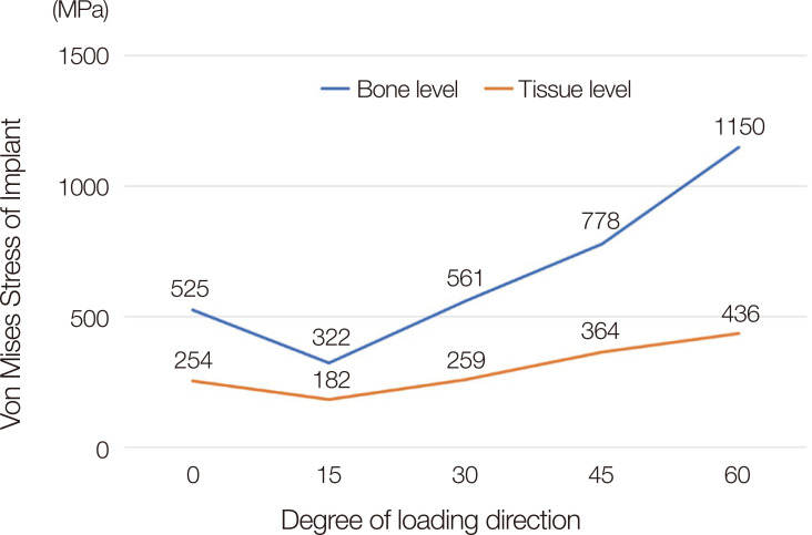
The stress values in the implant were as follows: 525, 322, 561, 778, and 1150 MPa in a bone level implant, and 254, 182, 259, 364, and 436 MPa in a tissue level implant at a load direction of 0, 15, 30, 45, and 60°, respectively. For microgap formation between the implant and abutment interface, three to seven-micron gaps were observed in the bone level implant under a load at 45 and 60°. In contrast, a three-micron gap was observed in the tissue level implant under a load at only 60°.
CONCLUSION
The mean stress of bone-level implant showed 2.2 times higher than that of tissue-level implant. When considering the loading point of occlusal surface and the direction of load, higher stress was noted when the vector was from the center of rotation in the implant prostheses.
Keywords: Finite element analysis, Torque, Dental stress analysis, Dental implant-abutment design, Weight-bearing
INTRODUCTION
Implant treatments have been successfully conducted in the dental field.1,2,3 Focusing on the mechanical complications of the dental implant, screw loosening during the five-year follow up was reported to be 8.8% for single crowns on implants and 11% for fixed dental prostheses with cantilevers on the implants.4,5,6 Screw loosening, abutment fractures, and implant fractures are the main mechanical complications of dental implants. Many studies have been performed to overcome these complications through a series of stress analyses, including a finite element analysis (FEA).7,8,9,10,11,12,13,14,15,16,17,18,19,20
Several factors influence the stress distribution of implant restorations, such as the crown height, type of the implant connection, the direction of the load, cusp inclination, size of the occlusal table, and implant angulation. The stress level of the implant increased with increasing crown height, which appears to be a more critical factor than the crown-implant ratio.15,21 This is related to the class I lever effect. The fulcrum, load arm, and effort arm should be considered carefully to understand the stress distribution of the implant restoration.
The difference in implant connections, such as internal, external, and tissue level, showed a significant difference in biomechanical aspects. The tissue level connection showed half of the stress level compared to the bone level connection because the transmucosal part of the tissue level implant decreases the length of the crown height and increases the diameter of connection compared to that of the bone level implant.8 On the other hand, the stress level under a 30° oblique load was 3.5 times higher than that of a vertical load, which was the most critical factor influencing the stress distribution of the implant components.8
In general, two types of loads have been applied in many studies, vertically and 30° obliquely. On the other hand, some studies did not reveal the precise loading position on the occlusal surface.22 A torque and lever effect can be produced when a vertical load is not applied to the center of the implant's axis.8 To the best of the author's knowledge, few studies have examined the comprehensive relationship of the direction of load, center of rotation, and stress distribution on the implant restoration simultaneously. Therefore, the correlation between the stress level and various directions of the load on the occlusal surface was examined under bone level and tissue level implant. The null hypothesis was that the stress value is not affected by the direction of load and connection type of implant.
MATERIALS AND METHODS
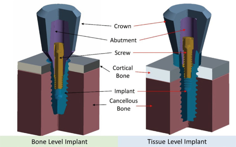
The following three-dimensional models were designed for the analysis: internal bone level (BL) and tissue level (TL) implants, abutment, screw, crown, and surrounding bone structure, including a 2 mm thickness of cortical bone and cancellous bone (Fig. 1). The implants had a diameter of 4.5 mm and a length of 10 mm for both groups. FEA was conducted to evaluate the von Mises stress and microgap formation on the implant and implant-abutment interface.
Fig. 1. Illustration of the design of the three-dimensional model.
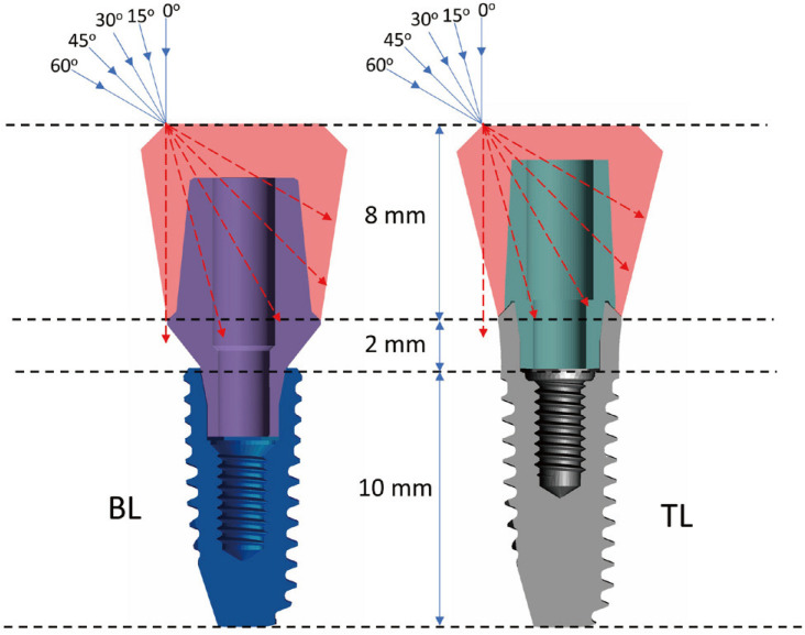
All components, such as cortical, cancellous bone, implant, screw, abutment, and crown, were designed using 3D software (Fusion 360, Autodesk, San Rafael, CA, USA). The distance from the cortical to the top of the crown was 10 mm, the same for BL and TL. The height of the transmucosal part of the TL implant and BL abutment was the same at 2 mm. The height of the crown was 8 mm, and the shape of the crown was designed geometrically in both groups. Each component was produced similarly on both groups only except for the implant connection and abutment. All the designed parts were converted to four nodes of tetrahedral elements to perform FEA. The number of elements was approximately 150,000 – 200,000 for each group.
The contact condition was managed for each facing surface. The interfaces among the implant, abutment, and screw were assumed to be a contacted surface with a 0.3 frictional coefficient.23 The other surfaces were set to the bonded contact to assume perfect osseointegration between the bone and implant, and perfect bonded conditions between the crown and abutment. All components were assumed to be isotropic, linearly elastic, and homogenous features. A 300 N preload was applied to mimic the intrinsic stress of the implant assembly caused by tightening the screw.24,25 A 200 N occlusal force in the direction of 0, 15, 30, 45, and 60° were applied to the occlusal area of the crown, assuming an off-axis area (Fig. 2). The highest von Mises stress of the implants was calculated for both groups under loads at five different directions. Subsequently, the microgap formed on the implant-abutment interface was calculated for both groups using the displacement button in the result tap in the software. The maximum distance between the implant and abutment surface under loading condition was analyzed to evaluate the microgap. The center of rotation of the restoration was also determined according to the various directions of the loads.
Fig. 2. Five directions of occlusal load assuming buccal cusp area.
The boundary conditions were fixed in the x-, y-, and z-direction on the mesial, distal, and bottom surfaces of cancellous bone to restrict unpredictable movement of the parts. Table 1 lists the elastic modulus and Poisson ratio of parts for the simulation.
Table 1. Materials properties used in FEA analysis.
RESULTS
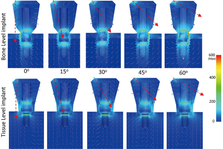
Figure 3 shows the highest von Mises stresses of the implants according to the various directions of the load. The stress of BL was 525, 322, 561, 778, and 1150 MPa under a load at 0, 15, 30, 45, and 60°, respectively. In contrast, the stress of TL was 254, 182, 259, 364, and 436 MPa under the same conditions. Figure 4 shows the overall color-coded figures of the stress distribution. The stress level and rotational torque were lower than the other group under a load at 15°.
Fig. 3. Stress level of two implants depending on the various load directions.
Fig. 4. Color-coded stress distribution under five directions of loads. The red arrow shows the direction of the occlusal load.
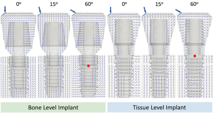
The center of rotation of the abutment under an oblique load was observed in the 60° load direction. In contrast, an upward tendency of the vector on the abutment was observed under a 15° load direction. A small amount of reverse torque was observed under a load at 0° compared to that at 60°. The same tendency on tissue level implant was determined (Fig. 5).
Fig. 5. Force vector of elements of the bone and tissue level implant under different directions of loads. The red dot shows the rotation center of the abutment. The small multiple arrows show force vector on the overall components under 0, 15 and 60 degree of load direction.
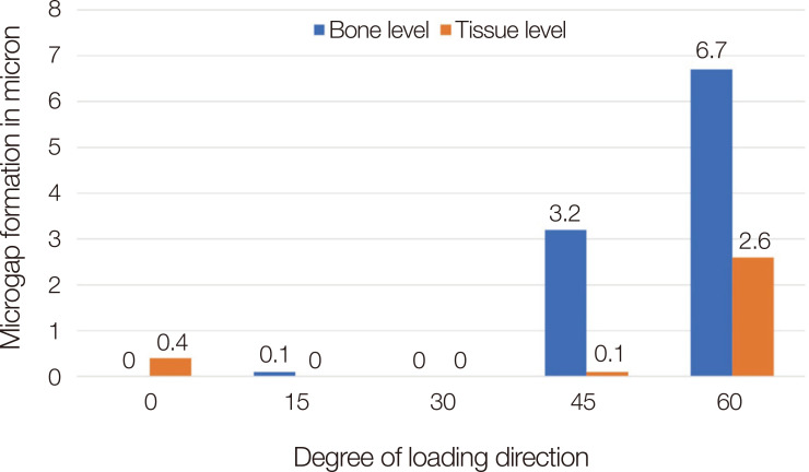
Figure 6 presents microgap formation on the implant abutment interfaces. The formation of a less than 1-micron gap was observed on BL under a load at a 0, 15, and 30° direction. Gaps of 3.2 microns and 6.7 microns were found at an oblique loading on BL at 45° and 60°, respectively. A gap of less than 1 micron was observed on TL under a load at 0, 15, 30 and 45°. A 2.6-micron gap was observed under a load on TL at 60°.
Fig. 6. Microgap between the implant-abutment connection.
DISCUSSION
The null hypothesis was rejected according to the result in this study. Among the various factors affecting the stress level applied to an implant, the direction of the force was a significant factor. There have been a few detailed studies focusing on the direction of the load. Therefore, FEA was performed to observe the stresses of implants at the bone and tissue levels under five loading directions.
Many studies applied the vertical force and a 30° oblique force in the mechanical loading tests on specimens or through computational analyses.8,21,22,26,27,28,29 Chang et al. applied a 100 N vertical and 30° oblique load on the occlusal surface of the implants. They reported that the stress level of the abutment under an oblique load was 10 – 20 times higher than that under a vertical load, but the precise loading points on the occlusal surface were not revealed.22 Lee et al.8 also applied a vertical and 30° oblique load on the occlusal surface of four different types of implants, and the stress level of the oblique loading was 3.5 times higher than that of a vertical load in general. They revealed the exact loading point on the occlusal surface. The vertical load was applied to the buccal cusps and central fossa of the occlusal surface, and the fulcrum area on the implant was observed in the vertical load in that study.
The results showed that the implant experienced a lateral force after applying a vertical load to where the axis of the load deviated from the axis of the implants. The stress level under a 15° oblique load showed the lowest value because the direction of the force pointed to the center of the connection, which would result in less torque on the implant and abutment. As the angle of load increased to 30, 45, and 60°, the stress level of the implants also increased accordingly. A 3.6 times difference was observed between 15 and 60° on BL, whereas a 2.4 times difference was noted in TL. The TL has a wider connection than BL, and the length of the crown from the connection to the occlusal surface is shorter than BL, which would result in a decrease in torque. The TL has a 2.8 mm height of transmucosal part, which reduces the crown height and makes it to be favorable in lever effect compared to that of the BL. The diameter of connection was 3.4 and 4.8 mm in BL and TL, respectively. Therefore, the base area of connection of the TL was 2 times larger than that of the BL. These factors seem to affect the results of stress value on implant restoration in this study.
In addition to the stress level, microgap formation occurred rapidly over a certain threshold. In particular, in the case of TL, microgap formation was not observed up to a 45° oblique load. In BL, microgaps were not observed under a 30° oblique load. The microgap would affect the bacterial microleakage of the implant, which is related to the peri-implantitis.30,31 The larger microgap means the higher deformation of titanium, and the deformation of titanium results in the stress of the implant.
The stress and microgap in TL and BL implants are related to torque on the implant component. To reduce the torque, the intrinsic resistance of the implant against the external load should be enhanced, and the extrinsic force should be minimized. The intrinsic factors are related to morphological aspects such as crown height, shape, the thickness of titanium, while the extrinsic factors are related to amount of load and direction of load. The stress and microgap could be controlled considering these factors simultaneously. The TL has a mechanical advantage compared to the BL in the aspect of morphology based on the result of this study.
Weinberg reported the correlations among the size of the occlusal surface, cusp inclination, and the vector of implant restorations in 1993.18 The decrease in stress was explained using two-dimensionally simplified figures by reducing the size of occlusal surface and the decreasing the angle of the cusps. In the era of digital dentistry, three-dimensional designs of individualized implant crowns were generated using computer-aided designing software in daily practice. Occlusal design will be performed considering the vectors of each occlusal contact points using vector analysis in the dental CAD software in the future.
The limitation of this study was that there was a difference between the FEA and various clinical situations. The design of the models was simplified compared to the real situation. For example, a cement layer was not included in this study, and the shape of crown was designed geometrically. These simplifications reduce the errors and duration of analysis, but they could increase the difference between the FEA and the real situation. Therefore, further studies are needed to apply the results to real condition. Additional experiments will be needed to verify this study through a mechanical test under various directions of loads with a number of specimens.
CONCLUSION
The vector from the occlusal surface and the position of the implant-abutment connection should be considered simultaneously for minimizing the stress of implants. Tissue level implant showed less stress value around the implant-abutment connection than bone level implant under the same load condition. The stress level was increased as the direction of the vector changes from the center of the implant connection.
Footnotes
This study was supported by Pusan National University Research Grant, 2019.
References
- 1.Tolstunov L. Implant zones of the jaws: implant location and related success rate. J Oral Implantol. 2007;33:211–220. doi: 10.1563/1548-1336(2007)33[211:IZOTJI]2.0.CO;2. [DOI] [PubMed] [Google Scholar]
- 2.Kandasamy B, Kaur N, Tomar GK, Bharadwaj A, Manual L, Chauhan M. Long-term retrospective study based on implant success rate in patients with risk factor: 15-year follow-up. J Contemp Dent Pract. 2018;19:90–93. doi: 10.5005/jp-journals-10024-2217. [DOI] [PubMed] [Google Scholar]
- 3.Carinci F. Survival and success rate of one-piece implant inserted in molar sites. Dent Res J (Isfahan) 2012;9:S155–S159. doi: 10.4103/1735-3327.109730. [DOI] [PMC free article] [PubMed] [Google Scholar]
- 4.Romeo E, Storelli S. Systematic review of the survival rate and the biological, technical, and aesthetic complications of fixed dental prostheses with cantilevers on implants reported in longitudinal studies with a mean of 5 years follow-up. Clin Oral Implants Res. 2012;23:39–49. doi: 10.1111/j.1600-0501.2012.02551.x. [DOI] [PubMed] [Google Scholar]
- 5.Pjetursson BE, Thoma D, Jung R, Zwahlen M, Zembic A. A systematic review of the survival and complication rates of implant-supported fixed dental prostheses (FDPs) after a mean observation period of at least 5 years. Clin Oral Implants Res. 2012;23:22–38. doi: 10.1111/j.1600-0501.2012.02546.x. [DOI] [PubMed] [Google Scholar]
- 6.Jung RE, Zembic A, Pjetursson BE, Zwahlen M, Thoma DS. Systematic review of the survival rate and the incidence of biological, technical, and aesthetic complications of single crowns on implants reported in longitudinal studies with a mean follow-up of 5 years. Clin Oral Implants Res. 2012;23:2–21. doi: 10.1111/j.1600-0501.2012.02547.x. [DOI] [PubMed] [Google Scholar]
- 7.Lee H, Kwon KR, Paek J, Pae A, Noh K. A Method for minimizing rotational errors of implant prostheses. Int J Oral Maxillofac Implants. 2017;32:1018–1022. doi: 10.11607/jomi.5324. [DOI] [PubMed] [Google Scholar]
- 8.Lee H, Park S, Noh G. Biomechanical analysis of 4 types of short dental implants in a resorbed mandible. J Prosthet Dent. 2019;121:659–670. doi: 10.1016/j.prosdent.2018.07.013. [DOI] [PubMed] [Google Scholar]
- 9.Hasan I, Heinemann F, Aitlahrach M, Bourauel C. Biomechanical finite element analysis of small diameter and short dental implant. Biomed Tech (Berl) 2010;55:341–350. doi: 10.1515/BMT.2010.049. [DOI] [PubMed] [Google Scholar]
- 10.Paek J, Woo YH, Kim HS, Pae A, Noh K, Lee H, Kwon KR. Comparative analysis of screw loosening with prefabricated abutments and customized CAD/CAM abutments. Implant Dent. 2016;25:770–774. doi: 10.1097/ID.0000000000000481. [DOI] [PubMed] [Google Scholar]
- 11.Lee H, Park S, Kwon KR, Noh G. Effects of cementless fixation of implant prosthesis: A finite element study. J Adv Prosthodont. 2019;11:341–349. doi: 10.4047/jap.2019.11.6.341. [DOI] [PMC free article] [PubMed] [Google Scholar]
- 12.Yoo JS, Kwon KR, Noh K, Lee H, Paek J. Stress analysis of mandibular implant overdenture with locator and bar/clip attachment: Comparative study with differences in the denture base length. J Adv Prosthodont. 2017;9:143–151. doi: 10.4047/jap.2017.9.3.143. [DOI] [PMC free article] [PubMed] [Google Scholar]
- 13.Ebadian B, Talebi S, Khodaeian N, Farzin M. Stress analysis of mandibular implant-retained overdenture with independent attachment system: effect of restoration space and attachment height. Gen Dent. 2015;63:61–67. [PubMed] [Google Scholar]
- 14.Nissan J, Ghelfan O, Gross O, Priel I, Gross M, Chaushu G. The effect of crown/implant ratio and crown height space on stress distribution in unsplinted implant supporting restorations. J Oral Maxillofac Surg. 2011;69:1934–1939. doi: 10.1016/j.joms.2011.01.036. [DOI] [PubMed] [Google Scholar]
- 15.Anitua E, Alkhraist MH, Piñas L, Begoña L, Orive G. Implant survival and crestal bone loss around extra-short implants supporting a fixed denture: the effect of crown height space, crown-to-implant ratio, and offset placement of the prosthesis. Int J Oral Maxillofac Implants. 2014;29:682–689. doi: 10.11607/jomi.3404. [DOI] [PubMed] [Google Scholar]
- 16.Araki H, Nakano T, Ono S, Yatani H. Three-dimensional finite element analysis of extra short implants focusing on implant designs and materials. Int J Implant Dent. 2020;6:5. doi: 10.1186/s40729-019-0202-6. [DOI] [PMC free article] [PubMed] [Google Scholar]
- 17.Watanabe F, Hata Y, Komatsu S, Ramos TC, Fukuda H. Finite element analysis of the influence of implant inclination, loading position, and load direction on stress distribution. Odontology. 2003;91:31–36. doi: 10.1007/s10266-003-0029-7. [DOI] [PubMed] [Google Scholar]
- 18.Weinberg LA. The biomechanics of force distribution in implant-supported prostheses. Int J Oral Maxillofac Implants. 1993;8:19–31. [PubMed] [Google Scholar]
- 19.Moon SY, Lim YJ, Kim MJ, Kwon HB. Three-dimensional finite element analysis of platform switched implant. J Adv Prosthodont. 2017;9:31–37. doi: 10.4047/jap.2017.9.1.31. [DOI] [PMC free article] [PubMed] [Google Scholar]
- 20.Adolfi D, Mendes Tribst JP, Souto Borges AL, Bottino MA. Torque maintenance capacity, vertical misfit, load to failure, and stress concentration of zirconia restorations cemented or notched to titanium bases. Int J Oral Maxillofac Implants. 2020;35:357–365. doi: 10.11607/jomi.7731. [DOI] [PubMed] [Google Scholar]
- 21.Bulaqi HA, Mousavi Mashhadi M, Safari H, Samandari MM, Geramipanah F. Effect of increased crown height on stress distribution in short dental implant components and their surrounding bone: A finite element analysis. J Prosthet Dent. 2015;113:548–557. doi: 10.1016/j.prosdent.2014.11.007. [DOI] [PubMed] [Google Scholar]
- 22.Chang HS, Chen YC, Hsieh YD, Hsu ML. Stress distribution of two commercial dental implant systems: A three-dimensional finite element analysis. J Dent Sci. 2013;8:261–271. [Google Scholar]
- 23.Alkan I, Sertgöz A, Ekici B. Influence of occlusal forces on stress distribution in preloaded dental implant screws. J Prosthet Dent. 2004;91:319–325. doi: 10.1016/j.prosdent.2004.01.016. [DOI] [PubMed] [Google Scholar]
- 24.Jörn D, Kohorst P, Besdo S, Rücker M, Stiesch M, Borchers L. Influence of lubricant on screw preload and stresses in a finite element model for a dental implant. J Prosthet Dent. 2014;112:340–348. doi: 10.1016/j.prosdent.2013.10.016. [DOI] [PubMed] [Google Scholar]
- 25.Zipprich H, Rathe F, Pinz S, Schlotmann L, Lauer HC, Ratka C. Effects of screw configuration on the preload force of implant-abutment screws. Int J Oral Maxillofac Implants. 2018;33:e25–e32. doi: 10.11607/jomi.5837. [DOI] [PubMed] [Google Scholar]
- 26.Wu T, Liao W, Dai N, Tang C. Design of a custom angled abutment for dental implants using computer-aided design and nonlinear finite element analysis. J Biomech. 2010;43:1941–1946. doi: 10.1016/j.jbiomech.2010.03.017. [DOI] [PubMed] [Google Scholar]
- 27.Faverani LP, Barao VAR, Ramalho-Ferreira G, Delben JA, Ferreira MB, Garcia IR, Jr, Assunção WG. The influence of bone quality on the biomechanical behavior of full-arch implant-supported fixed prostheses. Mater Sci Eng C Mater Biol Appl. 2014;37:164–170. doi: 10.1016/j.msec.2014.01.013. [DOI] [PubMed] [Google Scholar]
- 28.Hirata R, Bonfante EA, Machado LS, Tovar N, Coelho PG. Mechanical evaluation of two grades of titanium used in implant dentistry. Int J Oral Maxillofac Implants. 2015;30:800–805. doi: 10.11607/jomi.3742. [DOI] [PubMed] [Google Scholar]
- 29.Yang H, Park C, Shin JH, Yun KD, Lim HP, Park SW, Chung H. Stress distribution in premolars restored with inlays or onlays: 3D finite element analysis. J Adv Prosthodont. 2018;10:184–190. doi: 10.4047/jap.2018.10.3.184. [DOI] [PMC free article] [PubMed] [Google Scholar]
- 30.Zipprich H, Weigl P, Ratka C, Lange B, Lauer HC. The micromechanical behavior of implant-abutment connections under a dynamic load protocol. Clin Implant Dent Relat Res. 2018;20:814–823. doi: 10.1111/cid.12651. [DOI] [PubMed] [Google Scholar]
- 31.Zipprich H, Miatke S, Hmaidouch R, Lauer HC. A new experimental design for bacterial microleakage investigation at the implant-abutment interface: An in vitro study. Int J Oral Maxillofac Implants. 2016;31:37–44. doi: 10.11607/jomi.3713. [DOI] [PubMed] [Google Scholar]


